HR007GM201 - Drill MAKITA - Free user manual and instructions
Find the device manual for free HR007GM201 MAKITA in PDF.
Download the instructions for your Drill in PDF format for free! Find your manual HR007GM201 - MAKITA and take your electronic device back in hand. On this page are published all the documents necessary for the use of your device. HR007GM201 by MAKITA.
USER MANUAL HR007GM201 MAKITA
- Specicationsmaydierfromcountrytocountry.
- Theweightmaydierdependingontheattachment(s),includingthebatterycartridge.Thelightestandheavi- est combinations, according to EPTA-Procedure 01/2014, are shown in the table. Applicable battery cartridge and charger Battery cartridge BL4020* / BL4025* / BL4040* / BL4050F* : Recommended batteryCharger DC40RA / DC40RB / DC40RC
- Some of the battery cartridges and chargers listed above may not be available depending on your region of residence.
WARNING: Only use the battery cartridges and chargers listed above. Use of any other battery cartridges
andchargersmaycauseinjuryand/orre. Recommended cord connected power source Portable power pack PDC01 / PDC1200
- The cord connected power source(s) listed above may not be available depending on your region of residence.
- Before using the cord connected power source, read instruction and cautionary markings on them. Intended use The tool is intended for hammer drilling and drilling in brick, concrete and stone as well as for chiselling work. It is also suitable for drilling without impact in wood, metal, ceramic and plastic. Noise The typical A-weighted noise level determined accord- ing to EN62841-2-6: Model HR007G Sound pressure level (L
) : 104 dB (A) Uncertainty (K) : 3 dB(A)12 ENGLISH NOTE: The declared noise emission value(s) has been measured in accordance with a standard test method and may be used for comparing one tool with another. NOTE: The declared noise emission value(s) may also be used in a preliminary assessment of exposure.
WARNING: Wear ear protection.
WARNING: The noise emission during actual
use of the power tool can dier from the declared value(s) depending on the ways in which the tool is used especially what kind of workpiece is processed.
WARNING: Be sure to identify safety mea-
sures to protect the operator that are based on an estimation of exposure in the actual conditions of use (taking account of all parts of the operating cycle such as the times when the tool is switched o and when it is running idle in addition to the trigger time). Vibration The following table shows the vibration total value (tri-axial vector sum) determined according to applica- ble standard. Work mode Vibration emissionUncer-tainty (K)Applicable standard / Test conditionHammer drilling into concrete h, HD
EN62841-2-6Hammer drilling into concrete with DX15 (ah, HD
EN62841-2-6Chiselling (a
EN62841-2-6 NOTE: The declared vibration total value(s) has been measured in accordance with a standard test method and may be used for comparing one tool with another. NOTE: The declared vibration total value(s) may also be used in a preliminary assessment of exposure.
WARNING: The vibration emission during
actual use of the power tool can dier from the declared value(s) depending on the ways in which the tool is used especially what kind of workpiece is processed.
WARNING: Be sure to identify safety mea-
sures to protect the operator that are based on an estimation of exposure in the actual conditions of use (taking account of all parts of the operating cycle such as the times when the tool is switched o and when it is running idle in addition to the trigger time). Declarations of Conformity For European countries only The Declarations of conformity are included in Annex A to this instruction manual. SAFETY WARNINGS General power tool safety warnings WARNING Read all safety warnings, instruc- tions, illustrations and specications provided with this power tool. Failure to follow all instructions listed belowmayresultinelectricshock,reand/orserious injury. Save all warnings and instruc- tions for future reference. The term "power tool" in the warnings refers to your mains-operated (corded) power tool or battery-operated (cordless) power tool.
CORDLESS ROTARY HAMMER
SAFETY WARNINGS Safety instructions for all operations
1. Wear ear protectors. Exposure to noise can
2. Use auxiliary handle(s), if supplied with the
tool.Lossofcontrolcancausepersonalinjury.
3. Hold the power tool by insulated gripping
surfaces, when performing an operation where the cutting accessory may contact hidden wiring. Cutting accessory contacting a "live" wire may make exposed metal parts of the power tool "live" and could give the operator an electric shock. Safety instructions when using long drill bits with rotary hammers
1. Always start drilling at low speed and with the
bit tip in contact with the workpiece. At higher speeds, the bit is likely to bend if allowed to rotate freely without contacting the workpiece, resulting inpersonalinjury.
2. Apply pressure only in direct line with the bit
and do not apply excessive pressure. Bits can bend, causing breakage or loss of control, result- inginpersonalinjury. Additional safety warnings
1. Wear a hard hat (safety helmet), safety glasses
and/or face shield. Ordinary eye or sun glasses are NOT safety glasses. It is also highly recom- mended that you wear a dust mask and thickly padded gloves.
2. Be sure the bit is secured in place before
3. Under normal operation, the tool is designed
to produce vibration. The screws can come loose easily, causing a breakdown or accident. Check tightness of screws carefully before13 ENGLISH operation.
4. In cold weather or when the tool has not been
used for a long time, let the tool warm up for a while by operating it under no load. This will loosen up the lubrication. Without proper warm-up, hammering operation is dicult.
5. Always be sure you have a rm footing. Be
sure no one is below when using the tool in high locations.
6. Hold the tool rmly with both hands.
7. Keep hands away from moving parts.
8. Do not leave the tool running. Operate the tool
only when hand-held.
9. Do not point the tool at any one in the area
when operating. The bit could y out and injure someone seriously.
10. Do not touch the bit, parts close to the bit, or
workpiece immediately after operation; they may be extremely hot and could burn your skin.
11. Some material contains chemicals which may
be toxic. Take caution to prevent dust inhala- tion and skin contact. Follow material supplier safety data.
12. Always be sure that the tool is switched
o and the battery cartridge and the bit are removed before handing the tool to other person.
13. Before operation, make sure that there is no
buried object such as electric pipe, water pipe or gas pipe in the working area. Otherwise, the drill bit/chisel may touch them, resulting an electric shock, electrical leakage or gas leak.
14. Do not operate the tool at no-load
unnecessarily. SAVE THESE INSTRUCTIONS.
WARNING: DO NOT let comfort or familiarity
with product (gained from repeated use) replace strict adherence to safety rules for the subject product. MISUSE or failure to follow the safety rules stated in this instruction manual may cause serious personal injury. Important safety instructions for battery cartridge
1. Before using battery cartridge, read all instruc-
tions and cautionary markings on (1) battery charger, (2) battery, and (3) product using battery.
2. Do not disassemble or tamper with the battery
cartridge.Itmayresultinare,excessiveheat, or explosion.
3. If operating time has become excessively
shorter, stop operating immediately. It may result in a risk of overheating, possible burns and even an explosion.
4. If electrolyte gets into your eyes, rinse them
out with clear water and seek medical atten- tion right away. It may result in loss of your eyesight.
5. Do not short the battery cartridge:
(1) Do not touch the terminals with any con- ductive material. (2) Avoid storing battery cartridge in a con- tainer with other metal objects such as nails, coins, etc. (3) Do not expose battery cartridge to water or rain. A battery short can cause a large current ow, overheating, possible burns and even a breakdown.
6. Do not store and use the tool and battery car-
tridge in locations where the temperature may reach or exceed 50 °C (122 °F).
7. Do not incinerate the battery cartridge even if
it is severely damaged or is completely worn out. The battery cartridge can explode in a re.
8. Do not nail, cut, crush, throw, drop the battery
cartridge, or hit against a hard object to the battery cartridge. Such conduct may result in a re,excessiveheat,orexplosion.
9. Do not use a damaged battery.
10. The contained lithium-ion batteries are subject
to the Dangerous Goods Legislation require- ments. For commercial transports e.g. by third parties, forwarding agents, special requirement on pack- aging and labeling must be observed. For preparation of the item being shipped, consult- ing an expert for hazardous material is required. Please also observe possibly more detailed national regulations. Tapeormaskoopencontactsandpackupthe battery in such a manner that it cannot move around in the packaging.
11. When disposing the battery cartridge, remove
it from the tool and dispose of it in a safe place. Follow your local regulations relating to disposal of battery.
12. Use the batteries only with the products
specied by Makita. Installing the batteries to non-compliantproductsmayresultinare,exces- sive heat, explosion, or leak of electrolyte.
13. If the tool is not used for a long period of time,
the battery must be removed from the tool.
14. During and after use, the battery cartridge may
take on heat which can cause burns or low temperature burns. Pay attention to the han- dling of hot battery cartridges.
15. Do not touch the terminal of the tool imme-
diately after use as it may get hot enough to cause burns.
16. Do not allow chips, dust, or soil stuck into the
terminals, holes, and grooves of the battery cartridge.Itmaycauseheating,catchingre, burst and malfunction of the tool or battery car- tridge,resultinginburnsorpersonalinjury.
17. Unless the tool supports the use near
high-voltage electrical power lines, do not use the battery cartridge near high-voltage electri- cal power lines. It may result in a malfunction or breakdown of the tool or battery cartridge.
18. Keep the battery away from children.
SAVE THESE INSTRUCTIONS.14 ENGLISH
CAUTION: Only use genuine Makita batteries. Use of non-genuine Makita batteries, or batteries that have been altered, may result in the battery bursting causingres,personalinjuryanddamage.Itwill also void the Makita warranty for the Makita tool and charger. Tips for maintaining maximum battery life
1. Charge the battery cartridge before completely
discharged. Always stop tool operation and charge the battery cartridge when you notice less tool power.
2. Never recharge a fully charged battery car-
tridge. Overcharging shortens the battery service life.
3. Charge the battery cartridge with room tem-
perature at 10 °C - 40 °C (50 °F - 104 °F). Let a hot battery cartridge cool down before charging it.
4. When not using the battery cartridge, remove
it from the tool or the charger.
5. Charge the battery cartridge if you do not use
it for a long period (more than six months). Important safety instructions for wireless unit
1. Do not disassemble or tamper with the wire-
2. Keep the wireless unit away from young chil-
dren. If accidentally swallowed, seek medical attention immediately.
3. Use the wireless unit only with Makita tools.
4. Do not expose the wireless unit to rain or wet
5. Do not use the wireless unit in places where
the temperature exceeds 50 °C (122 °F).
6. Do not operate the wireless unit in places
where medical instruments, such as heart pace makers are nearby.
7. Do not operate the wireless unit in places
where automated devices are nearby. If oper- ated, automated devices may develop malfunction or error.
8. Do not operate the wireless unit in places
under high temperature or places where static electricity or electrical noise could be generated.
9. The wireless unit can produce electromagnetic
elds (EMF) but they are not harmful to the user.
10. The wireless unit is an accurate instrument. Be
careful not to drop or strike the wireless unit.
11. Avoid touching the terminal of the wireless
unit with bare hands or metallic materials.
12. Always remove the battery on the product
when installing the wireless unit into it.
13. When opening the lid of the slot, avoid the
place where dust and water may come into the slot. Always keep the inlet of the slot clean.
on the wireless unit too hard and/or press the button with an object with a sharp edge.
17. Do not remove the wireless unit from the slot
while the power is being supplied to the tool. Doing so may cause a malfunction of the wireless unit.
18. Do not remove the sticker on the wireless unit.
19. Do not put any sticker on the wireless unit.
20. Do not leave the wireless unit in a place where
static electricity or electrical noise could be generated.
21. Do not leave the wireless unit in a place sub-
ject to high heat, such as a car sitting in the sun.
22. Do not leave the wireless unit in a dusty or
powdery place or in a place corrosive gas could be generated.
23. Sudden change of the temperature may bedew
the wireless unit. Do not use the wireless unit until the dew is completely dried.
24. When cleaning the wireless unit, gently wipe
with a dry soft cloth. Do not use benzine, thin- ner, conductive grease or the like.
25. When storing the wireless unit, keep it in the
supplied case or a static-free container.
26. Do not insert any devices other than Makita
wireless unit into the slot on the tool.
27. Do not use the tool with the lid of the slot dam-
aged. Water, dust, and dirt come into the slot may cause malfunction.
damaged. SAVE THESE INSTRUCTIONS. FUNCTIONAL DESCRIPTION CAUTION: Always be sure that the tool is switched o and the battery cartridge is removed before adjusting or checking function on the tool.15 ENGLISH Installing or removing battery cartridge CAUTION: Always switch o the tool before installing or removing of the battery cartridge. CAUTION: Hold the tool and the battery car- tridge rmly when installing or removing battery cartridge. Failure to hold the tool and the battery cartridgermlymaycausethemtoslipoyourhands and result in damage to the tool and battery cartridge andapersonalinjury. ►Fig.1: 1. Red indicator 2. Button 3. Battery cartridge To remove the battery cartridge, slide it from the tool while sliding the button on the front of the cartridge. To install the battery cartridge, align the tongue on the battery cartridge with the groove in the housing and slip it into place. Insert it all the way until it locks in place with a little click. If you can see the red indicator as showninthegure,itisnotlockedcompletely. CAUTION: Always install the battery cartridge fully until the red indicator cannot be seen. If not, itmayaccidentallyfalloutofthetool,causinginjuryto you or someone around you. CAUTION: Do not install the battery cartridge forcibly. If the cartridge does not slide in easily, it is not being inserted correctly. Indicating the remaining battery capacity Press the check button on the battery cartridge to indi- cate the remaining battery capacity. The indicator lamps light up for a few seconds. ►Fig.2: 1. Indicator lamps 2. Check button Indicator lamps Remaining capacity Lighted O Blinking 75% to 100% 50% to 75% 25% to 50% 0% to 25% Charge the battery. The battery may have malfunctioned. NOTE: Depending on the conditions of use and the ambienttemperature,theindicationmaydierslightly from the actual capacity. NOTE:Therst(farleft)indicatorlampwillblinkwhen the battery protection system works. Tool / battery protection system The tool is equipped with a tool/battery protection sys- tem.Thissystemautomaticallycutsopowertothe motor to extend tool and battery life. The tool will auto- matically stop during operation if the tool or battery is placed under one of the following conditions: Overload protection When the battery is operated in a manner that causes it to draw an abnormally high current, the tool automat- ically stops without any indication. In this situation, turn thetooloandstoptheapplicationthatcausedthetool to become overloaded. Then turn the tool on to restart. Overheat protection When the tool or battery is overheated, the tool stops automatically. In this case, let the tool and battery cool before turning the tool on again. NOTE: When the tool is overheated, the lamp blinks. Overdischarge protection When the battery capacity is not enough, the tool stops automatically. In this case, remove the battery from the tool and charge the battery. Protections against other causes Protection system is also designed for other causes that could damage the tool and allows the tool to stop automatically. Take all the following steps to clear the causes, when the tool has been brought to a temporary halt or stop in operation.
1. Makesurethatallswitch(es)is/areintheoposi-
tion, and then turn the tool on again to restart.
2. Charge the battery(ies) or replace it/them with
recharged battery(ies).
3. Let the tool and battery(ies) cool down.
If no improvement can be found by restoring protection system, then contact your local Makita Service Center. Switch action
WARNING: Before installing the battery car-
tridge into the tool, always check to see that the switch trigger actuates properly and returns to the "OFF" position when released. ►Fig.3: 1. Switch trigger To start the tool, simply pull the switch trigger. Tool speed is increased by increasing pressure on the switch trigger. Release the switch trigger to stop. Lighting up the front lamp ►Fig.4: 1. Lamp16 ENGLISH CAUTION: Do not look in the light or see the source of light directly. Pull the switch trigger to light up the lamp. The lamp keeps on lighting while the switch trigger is being pulled. The lamp goes out approximately 10 seconds after releasing the switch trigger. CAUTION: If the lamp goes o after blinking for a few seconds, the active feedback sensing technology is not working properly. Ask your local Makita Service Center for repair. NOTE:Useadryclothtowipethedirtothelens of the lamp. Be careful not to scratch the lens of the lamp, or it may lower the illumination. NOTE: The front lamp cannot be used while the dust collection system (optional accessory) is installed in the tool. Reversing switch action ►Fig.5: 1. Reversing switch lever CAUTION: Always check the direction of rotation before operation. CAUTION: Use the reversing switch only after the tool comes to a complete stop. Changing the direction of rotation before the tool stops may dam- age the tool. CAUTION: When not operating the tool, always set the reversing switch lever to the neu- tral position. This tool has a reversing switch to change the direction of rotation. Depress the reversing switch lever from the A side for clockwise rotation or from the B side for coun- terclockwise rotation. When the reversing switch lever is in the neutral posi- tion, the switch trigger cannot be pulled. Selecting the action mode NOTICE: Do not rotate the action mode chang- ing knob when the tool is running. The tool will be damaged. NOTICE: To avoid rapid wear on the mode change mechanism, be sure that the action mode changing knob is always positively located in one of the three action mode positions. Rotation with hammering For drilling in concrete, masonry, etc., turn the action mode changing knob to the symbol while pressing the release button on the knob. Use a tungstencarbide tipped bit (optional accessory). ►Fig.6: 1. Rotation with hammering 2. Action mode changing knob 3. Release button Rotation only For drilling in wood, metal or plastic materials, turn the action mode changing knob to the symbol while pressing the release button on the knob. Use a twist drill bit or wood drill bit. ►Fig.7: 1. Rotation only Hammering only For chipping, scaling or demolition operations, turn the action mode changing knob to the symbol while pressing the release button on the knob. Use a bull point, cold chisel, scaling chisel, etc. ►Fig.8: 1. Hammering only Hook Optional accessory CAUTION: Always remove the battery when hanging the tool with the hook. CAUTION: Never hook the tool at high loca- tion or on potentially unstable surface. The hook is convenient for temporarily hanging the tool. Before installing the hook, remove the rubber cap from the screw holes in the mounting bracket. Insert the plate washers under the bracket, and then tighten the hook with screws in place. ►Fig.9: 1. Rubber cap 2. Mounting bracket 3. Plate washers 4. Hook 5. Screws For use, lift up the arm of the hook until it snaps into the open position. When not in use, be sure that the hook is folded back in the closed position. ►Fig.10: 1. Hook 2. Open position 3. Closed position ►Fig.11 Connecting lanyard (tether strap) to the hook CAUTION: Do not use damaged hook and screws. Before use, always check for damages, cracks or deformations, and make sure that the screws are tightened. CAUTION: Make sure that the hook is securely installed with the screws. CAUTION: Do not install or remove any accessory while hanging the tool. The tool may fall if the screws are not tightened. CAUTION: Always use a locking carabiner (multi-action and screw gate type) and be sure to attach the lanyard (tether strap) to the double looped portion of the hook. Improper attachment may cause tool drop from the hook and result in personalinjury. The hook is also used for connecting the lanyard (tether strap). Be sure to connect the lanyard (tether strap) to the double looped portion of the hook. ►Fig.12: 1. Double looped portion of the hook
2. Lanyard (tether strap) 3. Locking cara-
biner (multi-action and screw gate type)17 ENGLISH Safety warnings about connecting lanyard (tether strap) to the hook Safety warnings specic for use at height Read all safety warnings and instructions. Failure to follow the warnings and instructions may result in seriousinjury.
1. Always keep the tool tethered when working
"at height". Maximum lanyard length is 2 m. The maximum permissible fall height for lan- yard (tether strap) must not exceed 2 m.
2. Use only with lanyards appropriate for this tool
type and rated for at least 8.0 kg.
3. Do not anchor the tool lanyard to anything on
your body or on movable components. Anchor the tool lanyard to a rigid structure that can withstand the forces of a dropped tool.
4. Make sure the lanyard is properly secured at
each end prior to use.
5. Inspect the tool and lanyard before each use
for damage and proper function (including fabric and stitching). Do not use if damaged or not functioning properly.
6. Do not wrap lanyards around or allow them to
come in contact with sharp or rough edges.
7. Fasten the other end of the lanyard outside
the working area so that a falling tool is held securely.
8. Attach the lanyard so that the tool will move
away from the operator if it falls. Dropped tools willswingonthelanyard,whichcouldcauseinjury or loss of balance.
9. Do not use near moving parts or running
machinery. Failure to do so may result in a crush or entanglement hazard.
10. Do not carry the tool by the attachment device
11. Only transfer the tool between your hands
while you are properly balanced.
12. Do not attach lanyards to the tool in a way that
keeps switches or trigger-lock (if supplied) from operating properly.
13. Avoid getting tangled in the lanyard.
14. Keep lanyard away from the drilling area of the
15. Use a locking carabiner (multi-action and
screw gate type). Do not use single action spring clip carabiners.
16. In the event the tool is dropped, it must be
tagged and removed from service, and should be inspected by a Makita Factory or Authorized Service Center. Torque limiter NOTICE: As soon as the torque limiter actuates, switch o the tool immediately. This will help pre- vent premature wear of the tool. NOTICE: Drill bits such as hole saw, which tend to pinch or catch easily in the hole, are not appro- priate for this tool. This is because they will cause the torque limiter to actuate too frequently. The torque limiter will actuate when a certain torque level is reached. The motor will disengage from the output shaft. When this happens, the drill bit will stop turning. Electronic function The tool is equipped with the electronic functions for easy operation.
- Electric brake This tool is equipped with an electric brake. If the tool consistently fails to quickly cease to function after the switch trigger is released, have the tool serviced at a Makita service center.
- Constant speed control The speed control function provides the constant rotation speed regardless of load conditions.
- Active Feedback sensing Technology If the tool is swung at the predetermined accelera- tion during operation, the motor is forcibly stopped to reduce the burden on the wrist. NOTE: This function does not work if the acceleration does not reach the predetermined one when the tool is swung. NOTE: If the bit is swung at the predetermined acceleration during chipping, scaling, or demolishing, the motor is forcibly stopped. In this case, release the switch trigger, and then pull the switch trigger to restart the tool. ASSEMBLY CAUTION: Always be sure that the tool is switched o and the battery cartridge is removed before carrying out any work on the tool. Side grip (auxiliary handle) CAUTION: Always use the side grip to ensure safe operation. CAUTION: After installing or adjusting the side grip, make sure that the side grip is rmly secured with its retaining projections fully engaged by the positioning recesses on the gear housing. To install the side grip, follow the steps below.
1. Loosen the thumb screw on the side grip. Then
install the side grip over the barrel neck of the gear housing. ►Fig.13: 1. Side grip 2. Thumb screw 3. Barrel neck of the gear housing 4.Retainingprojection
5. Positioning recess
The attachment ring can be enlarged by pressing the thumb screw down so that the ring is easily and securely engaged over the barrel neck of the gear housing. ►Fig.14: 1. Thumb screw 2. Attachment ring
2. Tighten the thumb screw to secure the grip at your
desired angle.18 ENGLISH Grease Optional accessory Coat the shank end of the drill bit beforehand with a small amount of grease (about 0.5 - 1 g). This chuck lubrication assures smooth action and lon- ger service life. Installing and removing drill bit Clean the shank end of the drill bit and apply grease before installing the drill bit. ►Fig.15: 1. Shank end 2. Grease Place the shank end of the drill bit into the chuck, and insert it further into the chuck while hand-turning the drillbitsotheshankendwelltsintothechuckslotand becomes fully engaged. Having installed the drill bit, try pulling it back to ensure it is securely held in place. ►Fig.16: 1. Drill bit 2. Chuck To remove the drill bit, push the chuck cover down all the way and pull the drill bit out. ►Fig.17: 1. Drill bit 2. Chuck cover Chisel angle (when chipping, scaling or demolishing) The chisel can be secured at the desired angle. Switch the action mode changing knob to the O symbol, and then turn the chisel to your desired angle. ►Fig.18: 1. Action mode changing knob 2. O symbol Switch the action mode changing knob to the sym- bol. Try hand-turning the chisel to ensure it is securely held in place. Depth gauge The depth gauge is convenient for drilling holes of uniform depth. Press and hold the lock button, and then insert the depth gauge into the hex hole. Make sure that the toothed side of the depth gauge faces the toothed mark- ing on the hex hole. ►Fig.19: 1. Depth gauge 2. Lock button 3. Hex hole
4. Toothed side 5. Toothed marking
Adjustthedepthgaugebymovingitbackandforth whilepressingthelockbutton.Aftertheadjustment, release the lock button to lock the depth gauge. NOTE: Make sure that the depth gauge does not touch the main body of the tool when attaching it. Dust collection system Optional accessory Installation
1. Slide the air duct cap out of the motor housing
while lifting the lock tab up to the unlocked position. ►Fig.20: 1. Air duct cap 2. Lock tab
2. Mount the tool onto the dust collection system by
sliding the guide grooves on bottom surface of the gear housing over the guide rails on top surface of the dust collection system until it locks in place with a click. ►Fig.21: 1. Guide grooves 2. Guide rails 3. Dust collection system Uninstallation
1. Dismount the tool from the dust collection system
byslidingthetoolawayowhilepressingthelocko button on the dust collection system. ►Fig.22: 1. Dust collection system 2.Lockobutton
2. Slide the air duct cap back along the guide
grooves on gear housing until it locks in place with a click. ►Fig.23: 1. Air duct cap 2. Guide grooves NOTICE: Make sure to place the air duct cap back over the air duct after detaching the dust collection system from the tool. Tool performance canbeaectedifitisoperatedwithouttheairduct cap in place. Adjusting nozzle position Slide in and out the nozzle guide while pressing the guideadjustmentbutton,andthenreleasethebutton atanexactpositionwherethetipofthedrillbitsitsjust behind the front surface of the nozzle. ►Fig.24: 1. Nozzle guide 2.Guideadjustmentbutton
3. Tip of drill bit 4. Front surface of nozzle
NOTE:Beforeadjustingthenozzleposition,press theguideadjustmentbuttontoreleasethetensionon the nozzle guide and set it free into a fully extended position. Adjusting drilling depths Drillingdepthcanbeadjustedbychangingthelengths betweenthedepthadjustmentbuttonandrearendof thenozzleguide.Pressandholdthedepthadjustment button and slide it to your desired position. ►Fig.25: 1.Depthadjustmentbutton2. Nozzle guide
Storage NOTICE: When not in use for a certain period of time, the nozzle guide needs to be extended to approximately 100 mm from its fully shortened position. Failing to do so may damage the duct hose pre-installed in the nozzle guide. ►Fig.26: 1.Guideadjustmentbutton2. Approx. 100 mm Dust cup Optional accessory Use the dust cup to prevent dust from falling over the tool and on yourself when performing overhead drilling operations. Attach the dust cup to the bit as shown in thegure.Thesizeofbitswhichthedustcupcanbe attached to is as follows. Model Bit diameter19 ENGLISH Dust cup 5 6 mm - 14.5 mm Dust cup 9 12 mm - 16 mm ►Fig.27: 1. Dust cup Dust cup set Optional accessory CAUTION: Before installing and uninstalling the dust cup set, remove a bit from the tool. Installation Place the dust cup set onto the barrel neck of the gear housing aligning the symbol on the dust cup with one of the grooves in the barrel. Then hold the attach- ment unit of the dust cup set and push it down onto the barrel to secure it in place. ►Fig.28: 1. Dust cup set 2. Attachment unit
NOTE: If you connect a vacuum cleaner to the dust cup set, remove the dust cap before connecting it. ►Fig.29: 1. Dust cap Uninstallation Pushthechuckcoverdownallthewayandpullabito. ►Fig.30: 1. Bit 2. Chuck cover Hold the attachment unit of the dust cup set and pull it apart from the tool. ►Fig.31: 1. Attachment unit NOTE:Ifthecapcomesofromthedustcupset, place it back to the original position.
1. Detach the bellows from the attachment unit of the
dust cup set. ►Fig.32: 1. Bellows 2. Attachment unit
2. Set the cap back in place with its printed side
facing upwards. ►Fig.33: 1. Cap 2. Printed side 3. Grooves 4. Lips of upper opening 5. Attachment unit
3. Besurethatthegroovesaroundthecapwelltin
the lips of the upper opening of the attachment unit. ►Fig.34 OPERATION CAUTION: Always use the side grip (auxiliary handle) and rmly hold the tool by both side grip and switch handle during operations. CAUTION: Always make sure that the work- piece is secured before operation. CAUTION: Do not pull the tool out forcibly even the bit gets stuck. Loss of control may cause injury. CAUTION: The dust collection system is intended for drilling in concrete only. Do not use the dust collection system for drilling in metal or wood. CAUTION: When using the tool with the dust collection system, be sure to attach the lter to the dust collection system to prevent dust inhalation. CAUTION: Before using the dust collection system, check that the lter is not damaged. Failure to do so may cause dust inhalation. CAUTION: The dust collection system col- lects the generated dust at a considerable rate, but not all dust can be collected. NOTICE: If the tool is operated continuously at low speed for a long time, the motor will get over- loaded, resulting in tool malfunction. NOTICE: Do not use the dust collection system for core drilling or chiseling. NOTICE: Do not use the dust collection system for drilling in wet concrete or use this system in wet environment. Failure to do so may cause malfunction. NOTE: If the battery cartridge is in low temperature, the tool’s capability may not be fully obtained. In this case, warm up the battery cartridge by using the tool with no load for a while to fully obtain the tool’s capability. ►Fig.35 Hammer drilling operation CAUTION: There is tremendous and sudden twisting force exerted on the tool/drill bit at the time of hole break-through, when the hole becomes clogged with chips and particles, or when striking reinforcing rods embedded in the concrete. Always use the side grip (auxiliary handle) and rmly hold the tool by both side grip and switch handle during opera- tions. Failure to do so may result in the loss of control ofthetoolandpotentiallysevereinjury. Set the action mode changing knob to the symbol. Position the drill bit at the desired location for the hole, then pull the switch trigger. Apply feed force to the switch handle (main handle) for workingaccuracyandeciency,andholdthesidegrip (auxiliary handle) to keep balance of the tool. Keep the tool in position and prevent it from slipping away from the hole. Do not apply more pressure when the hole becomes clogged with chips or particles. Instead, run the tool at an idle, then remove the drill bit partially from the hole. By repeating this several times, the hole will be cleaned out and normal drilling may be resumed. NOTE: Eccentricity in the drill bit rotation may occur while operating the tool with no load. The tool auto- matically centers itself during operation. This does not aectthedrillingprecision.20 ENGLISH Chipping/Scaling/Demolition Set the action mode changing knob to the symbol. Holdthetoolrmlywithbothhands.Turnthetoolon. Apply feed force to the switch handle (main handle) for workingaccuracyandeciency,andholdthesidegrip (auxiliary handle) to keep balance of the tool. Pressing very hard on the tool will not increase the eciency. ►Fig.36 Drilling in wood or metal CAUTION: Hold the tool rmly and exert care when the drill bit begins to break through the workpiece. There is a tremendous force exerted on the tool/drill bit at the time of hole break through. CAUTION: A stuck drill bit can be removed simply by setting the reversing switch to reverse rotation in order to back out. However, the tool may back out abruptly if you do not hold it rmly. CAUTION: Always secure workpieces in a vise or similar hold-down device. NOTICE: Never use “rotation with hammering” when the drill chuck is installed on the tool. The drill chuck may be damaged. Also,thedrillchuckwillcomeowhenreversingthe tool. NOTICE: Pressing excessively on the tool will not speed up the drilling. In fact, this excessive pressure will only serve to damage the tip of your drill bit, decrease the tool performance and shorten the service life of the tool. Set the action mode changing knob to the symbol. Installing drill chuck set Optional accessory Attach the chuck adapter to a keyless drill chuck to which 1/2"-20 size screw can be installed, and then install them to the tool. For details on how to install the adapter into the chuck, refer to the instructions on installing drill bit. ►Fig.37: 1. Keyless drill chuck 2. Chuck adapter Diamond core drilling NOTICE: If performing diamond core drilling operations using “rotation with hammering” action, the diamond core bit may be damaged. When performing diamond core drilling opera- tions, always set the action mode changing knob to the position to use "rotation only" action. Beating dust on the lter Optional accessory CAUTION: Do not turn the dial on the dust case while the dust case is removed from the dust collection system. Doing so may cause dust inhalation. CAUTION: Always switch o the tool when turning the dial on the dust case. Turning the dial while the tool is running may result in the loss of control of the tool. Bybeatingthedustonthelterinsidethedustcase, youcankeepthevacuumeciencyandalsoreducethe number of times to dispose of the dust. Turn the dial on the dust case three times after col- lecting every 50,000 mm
of dust or when you feel the vacuum performance declined. NOTE: 50,000 mm
of dust equivalents to drilling 10 holes of ø10 mm and 65 mm depth. ►Fig.38: 1. Dust case 2. Dial Disposing of dust Optional accessory CAUTION: Always be sure that the tool is switched o and the battery cartridge is removed before carrying out any work on the tool. CAUTION: Be sure to wear dust mask when disposing of dust. CAUTION: Empty the dust case regularly before the dust case becomes full. Failure to do so may decrease the dust collection performance and cause dust inhalation. CAUTION: The performance of dust collection decreases if the lter in the dust case become clogged. Replace the lter with new one after approximately 200 times of dust fulllment as a guide. Failure to do so may cause dust inhalation.
1. Remove the dust case while pressing down the
latch lever of the dust case. ►Fig.39: 1. Latch lever
2. Lift the lock tab slightly outwards and open the
dust case cover. ►Fig.40: 1. Dust case cover 2. Lock tab
3. Disposeofthedust,andthencleanthelter.
►Fig.41 NOTICE: When cleaning the lter, tap the case of the lter gently by hand to remove dust. Do not tap the lter directly; touch the lter with brush or similar; or blow compressed air on the lter. Doing so may damage the lter. Blow-out bulb Optional accessory After drilling the hole, use the blow-out bulb to clean the dust out of the hole.21 ENGLISH ►Fig.42 Using dust cup set Optional accessory Fit the dust cup set against the ceiling when operating the tool. ►Fig.43 NOTICE: Do not use the dust cup set when drill- ing in metal or similar. It may damage the dust cup set due to the heat produced by small metal dust or similar. NOTICE: Do not install or remove the dust cup set with the drill bit installed in the tool. It may damage the dust cup set and cause dust leak. WIRELESS ACTIVATION FUNCTION What you can do with the wireless activation function The wireless activation function enables clean and com- fortable operation. By connecting a supported vacuum cleaner to the tool, you can run the vacuum cleaner automatically along with the switch operation of the tool. ►Fig.44 To use the wireless activation function, prepare follow- ing items:
- A wireless unit (optional accessory)
- A vacuum cleaner which supports the wireless activation function The overview of the wireless activation function setting is as follows. Refer to each section for detail procedures.
1. Installing the wireless unit
2. Tool registration for the vacuum cleaner
3. Starting the wireless activation function
Installing the wireless unit Optional accessory CAUTION: Place the tool on a at and stable surface when installing the wireless unit. NOTICE: Clean the dust and dirt on the tool before installing the wireless unit. Dust or dirt may cause malfunction if it comes into the slot of the wireless unit. NOTICE: To prevent the malfunction caused by static, touch a static discharging material, such as a metal part of the tool, before picking up the wireless unit. NOTICE: When installing the wireless unit, always be sure that the wireless unit is inserted in the correct direction and the lid is completely closed.
2. Insert the wireless unit to the slot and then close
the lid. Wheninsertingthewirelessunit,aligntheprojections with the recessed portions on the slot. ►Fig.46: 1. Wireless unit 2.Projection3. Lid
When removing the wireless unit, open the lid slowly. The hooks on the back of the lid will lift the wireless unit as you pull up the lid. ►Fig.47: 1. Wireless unit 2. Hook 3. Lid After removing the wireless unit, keep it in the supplied case or a static-free container. NOTICE: Always use the hooks on the back of the lid when removing the wireless unit. If the hooks do not catch the wireless unit, close the lid completely and open it slowly again. Tool registration for the vacuum cleaner NOTE: A Makita vacuum cleaner supporting the wireless activation function is required for the tool registration. NOTE: Finish installing the wireless unit to the tool before starting the tool registration. NOTE: During the tool registration, do not pull the switch trigger or turn on the power switch on the vacuum cleaner. NOTE: Refer to the instruction manual of the vacuum cleaner, too. If you wish to activate the vacuum cleaner along with theswitchoperationofthetool,nishthetoolregistra- tion beforehand.
1. Install the batteries to the vacuum cleaner and the
2. Set the stand-by switch on the vacuum cleaner to
"AUTO". ►Fig.48: 1. Stand-by switch
3. Press the wireless activation button on the vac-
uum cleaner for 3 seconds until the wireless activation lamp blinks in green. And then press the wireless acti- vation button on the tool in the same way. ►Fig.49: 1. Wireless activation button 2. Wireless activation lamp22 ENGLISH If the vacuum cleaner and the tool are linked success- fully, the wireless activation lamps will light up in green for 2 seconds and start blinking in blue. NOTE:Thewirelessactivationlampsnishblinking in green after 20 seconds elapsed. Press the wireless activation button on the tool while the wireless acti- vation lamp on the cleaner is blinking. If the wireless activation lamp does not blink in green, push the wire- lessactivationbuttonbrieyandholditdownagain. NOTE: When performing two or more tool registra- tionsforonevacuumcleaner,nishthetoolregistra- tion one by one. Starting the wireless activation function NOTE: Finish the tool registration for the vacuum cleaner prior to the wireless activation. NOTE: Refer to the instruction manual of the vacuum cleaner, too. After registering a tool to the vacuum cleaner, the vac- uum cleaner will automatically run along with the switch operation of the tool.
1. Install the wireless unit to the tool.
2. Connect the hose of the vacuum cleaner with the
3. Set the stand-by switch on the vacuum cleaner to
5. Turn on the tool. Check if the vacuum cleaner runs
while the tool is operating. To stop the wireless activation of the vacuum cleaner, push the wireless activation button on the tool. NOTE: The wireless activation lamp on the tool will stop blinking in blue when there is no operation for 2 hours. In this case, set the stand-by switch on the vacuum cleaner to "AUTO" and push the wireless activation button on the tool again. NOTE: The vacuum cleaner starts/stops with a delay. There is a time lag when the vacuum cleaner detects a switch operation of the tool. NOTE: The transmission distance of the wireless unit may vary depending on the location and surrounding circumstances. NOTE: When two or more tools are registered to one vacuum cleaner, the vacuum cleaner may start running even if you do not turn on your tool because another user is using the wireless activation function. Description of the wireless activation lamp status ►Fig.53: 1. Wireless activation lamp The wireless activation lamp shows the status of the wireless activation function. Refer to the table below for the meaning of the lamp status. Status Wireless activation lamp Description Color
Blinking Duration Standby Blue 2 hours The wireless activation of the vacuum cleaner is available. The lampwillautomaticallyturnowhennooperationisperformed for 2 hours. When the tool is running. The wireless activation of the vacuum cleaner is available and the tool is running. Tool registration Green 20 seconds Ready for the tool registration. Waiting for the registration by the vacuum cleaner. 2 seconds Thetoolregistrationhasbeennished.Thewirelessactivation lamp will start blinking in blue. Cancelling tool registration Red 20 seconds Ready for the cancellation of the tool registration. Waiting for the cancellation by the vacuum cleaner. 2 seconds Thecancellationofthetoolregistrationhasbeennished.The wireless activation lamp will start blinking in blue. Others Red 3 seconds The power is supplied to the wireless unit and the wireless activa- tion function is starting up. O - - The wireless activation of the vacuum cleaner is stopped. Cancelling tool registration for the vacuum cleaner Perform the following procedure when cancelling the tool registration for the vacuum cleaner.
1. Install the batteries to the vacuum cleaner and the
2. Set the stand-by switch on the vacuum cleaner to
"AUTO". ►Fig.54: 1. Stand-by switch
3. Press the wireless activation button on the vac-
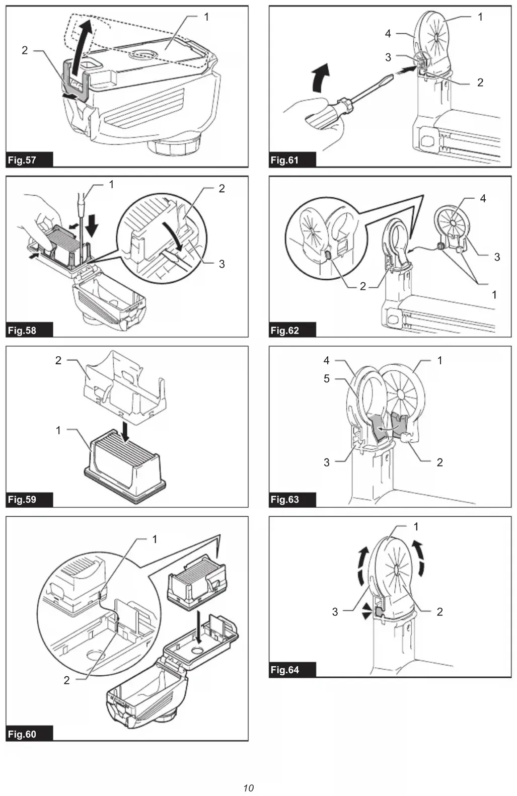
uum cleaner for 6 seconds. The wireless activation23 ENGLISH lamp blinks in green and then become red. After that, press the wireless activation button on the tool in the same way. ►Fig.55: 1. Wireless activation button 2. Wireless activation lamp If the cancellation is performed successfully, the wire- less activation lamps will light up in red for 2 seconds and start blinking in blue. NOTE:Thewirelessactivationlampsnishblinkingin red after 20 seconds elapsed. Press the wireless acti- vation button on the tool while the wireless activation lamp on the cleaner is blinking. If the wireless acti- vation lamp does not blink in red, push the wireless activationbuttonbrieyandholditdownagain. Troubleshooting for wireless activation function Beforeaskingforrepairs,conductyourowninspectionrst.Ifyoundaproblemthatisnotexplainedinthemanual, do not attempt to dismantle the tool. Instead, ask Makita Authorized Service Centers, always using Makita replace- ment parts for repairs. State of abnormality Probable cause (malfunction) Remedy The wireless activation lamp does not light/blink. The wireless unit is not installed into the tool. The wireless unit is improperly installed into the tool. Install the wireless unit correctly. The terminal of the wireless unit and/or the slot is dirty. Gentlywipeodustanddirtontheterminalofthe wireless unit and clean the slot. The wireless activation button on the tool has not been pushed. Push the wireless activation button on the tool briey. The stand-by switch on the vacuum cleaner is not set to "AUTO". Set the stand-by switch on the vacuum cleaner to "AUTO". No power supply Supply the power to the tool and the vacuum cleaner. Cannotnishtoolregistration/can- celling tool registration successfully. The wireless unit is not installed into the tool. The wireless unit is improperly installed into the tool. Install the wireless unit correctly. The terminal of the wireless unit and/or the slot is dirty. Gentlywipeodustanddirtontheterminalofthe wireless unit and clean the slot. The stand-by switch on the vacuum cleaner is not set to "AUTO". Set the stand-by switch on the vacuum cleaner to "AUTO". No power supply Supply the power to the tool and the vacuum cleaner. Incorrect operation Pushthewirelessactivationbuttonbrieyand perform the tool registration/cancellation procedures again. The tool and vacuum cleaner are away from each other (out of the transmission range). Get the tool and vacuum cleaner closer to each other. The maximum transmission distance is approximately 10 m however it may vary according to the circumstances. Beforenishingthetoolregistration/ cancellation; - the switch of the tool is turned on or; - the power button on the vacuum cleaner is turned on. Pushthewirelessactivationbuttonbrieyand perform the tool registration/cancellation procedures again. The tool registration procedures for the tool or vacuum cleaner have not nished. Perform the tool registration procedures for both the tool and the vacuum cleaner at the same timing. Radio disturbance by other appliances which generate high-intensity radio waves. Keep the tool and vacuum cleaner away from the appliances such as Wi-Fi devices and microwave ovens.24 ENGLISH State of abnormality Probable cause (malfunction) Remedy The vacuum cleaner does not run along with the switch operation of the tool. The wireless unit is not installed into the tool. The wireless unit is improperly installed into the tool. Install the wireless unit correctly. The terminal of the wireless unit and/or the slot is dirty. Gentlywipeodustanddirtontheterminalofthe wireless unit and clean the slot. The wireless activation button on the tool has not been pushed. Pushthewirelessactivationbuttonbrieyandmake sure that the wireless activation lamp is blinking in blue. The stand-by switch on the vacuum cleaner is not set to "AUTO". Set the stand-by switch on the vacuum cleaner to "AUTO". More than 10 tools are registered to the vacuum cleaner. Perform the tool registration again. If more than 10 tools are registered to the vacuum cleaner, the tool registered earliest will be cancelled automatically. The vacuum cleaner erased all tool registrations. Perform the tool registration again. No power supply Supply the power to the tool and the vacuum cleaner. The tool and vacuum cleaner are away from each other (out of the transmission range). Get the tool and vacuum cleaner closer each other. The maximum transmission distance is approxi- mately 10 m however it may vary according to the circumstances. Radio disturbance by other appliances which generate high-intensity radio waves. Keep the tool and vacuum cleaner away from the appliances such as Wi-Fi devices and microwave ovens. The vacuum cleaner runs while the tool is not operating. Other users are using the wireless activation of the vacuum cleaner with their tools. Turnothewirelessactivationbuttonoftheother tools or cancel the tool registration of the other tools. MAINTENANCE CAUTION: Always be sure that the tool is switched o and the battery cartridge is removed before attempting to perform inspection or maintenance. NOTICE: Never use gasoline, benzine, thinner, alcohol or the like. Discoloration, deformation or cracks may result. To maintain product SAFETY and RELIABILITY, repairs,anyothermaintenanceoradjustmentshould be performed by Makita Authorized or Factory Service Centers, always using Makita replacement parts. Replacing lter of dust case Optional accessory
1. Remove the dust case while pressing down the
latch lever of the dust case. ►Fig.56: 1. Latch lever
2. Lift the lock tab slightly outwards and open the
6. Close the dust case cover, and then reassemble
the dust case to the dust collection system. Replacing sealing cap Optional accessory Replace a sealing cap at regular intervals as a worn ordamagedsealingcapmayaectthesuction performance.
1. Insertaat-bladescrewdriver,withitsatsurfaces
vertical, into one of the release holes placed on the sidesofthenozzlehead.Tilttheat-bladescrewdriver at an angle to squeeze and pop the cube hook of the sealing cap out of the molded receptacle. Then peel the rubber edges of the sealing cap away from the rims of the nozzle head opening. ►Fig.61: 1. Sealing cap 2. Cube hook 3. Release hole 4. Nozzle head
2. Set one of cube hooks of a renewed sealing cap
into the molded receptacle in the nozzle head with a recessed surface of the sealing cap facing forwards. ►Fig.62: 1. Cube hooks 2. Receptacles 3. Sealing cap 4. Recessed surface
3. Place the other hook into the receptacle on the25 ENGLISH
4. Gently lay the rubber edges of the sealing cap
down over the rims of the nozzle head opening from bottom to top. ►Fig.64: 1. Rubber edges 2. Sealing cap 3. Nozzle head OPTIONAL ACCESSORIES CAUTION: These accessories or attachments are recommended for use with your Makita tool specied in this manual. The use of any other accessories or attachments might present a risk of injurytopersons.Onlyuseaccessoryorattachment for its stated purpose. If you need any assistance for more details regard- ing these accessories, ask your local Makita Service Center.
- Drill chuck set (chuck adapter / drill chuck)