
FHDSF1100BL - Range hood FALCON - Free user manual and instructions
Find the device manual for free FHDSF1100BL FALCON in PDF.
| Product type | Range hood |
| Brand | Falcon |
| Model | FHDSF1100BL |
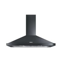
| Installation type | Wall-mounted |
| Operation | Exhausting or recirculating (recirculation with charcoal filter) |
| Number of speeds | 4 (including one timed for 6 minutes) |
| Control | Push buttons with indicator lights |
| Lighting | Yes, dedicated switch |
| Air outlet diameter | 150 mm (reducer 120-125 mm supplied) |
| Main material | Stainless steel |
| Grease filters | Metallic, dishwasher safe (every 2 months) |
| Charcoal filter | Optional, replace every 4 months |
| Supply voltage | 220-240 V |
| Frequency | 50 Hz |
| Insulation class | Class I (grounding required) |
| Minimum distance to cooking surface | 650 mm |
| Chimney height | Telescopic, adjustable |
| Package contents | Hood body, telescopic chimney, mounting kit, reducer, manual |
| Maintenance | Clean grease filters every 2 months; replace charcoal filter every 4 months |
| Repairability | Spare parts available: filters, bulbs, contact after-sales service |
Frequently Asked Questions - FHDSF1100BL FALCON
User questions about FHDSF1100BL FALCON
0 question about this device. Answer the ones you know or ask your own.
Ask a new question about this device
Download the instructions for your Range hood in PDF format for free! Find your manual FHDSF1100BL - FALCON and take your electronic device back in hand. On this page are published all the documents necessary for the use of your device. FHDSF1100BL by FALCON.
USER MANUAL FHDSF1100BL FALCON
natural_image
Isometric line drawing of a vertical shelf or support structure with a base platform (no text or symbols)SAFETY INFORMATION......13
CHARACTERISTICS 16
INSTALLATION....17
USE 20
CARE AND CLEANING....21
SOMMAIRE
FR
CONSIGNES DE SÉCURITÉ....22
CARACTERISTIQUES....25
INSTALLATION....26
UTILISATION 29
NETTOYAGE ET ENTRETIEN 30
INHALTSVERZEICHNIS
DE
natural_image
Pure architectural line drawing of a staircase with stairs and columns (no text or symbols)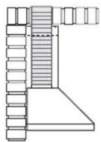
natural_image
Architectural line drawing of a staircase with stairs and windows (no text or symbols)natural_image
Diagram showing a mechanical component with a green arrow indicating direction, no text or symbols presentMontaggio Camino
Camino superiore

Quadro comandi
TASTO LED FUNZIONI
natural_image
Hand pressing a green arrow on a device component, enclosed in a circular frame (no text or symbols)Filtro antiodore (Versione Filtrante)
SOSTITUZIONE FILTRO ANTIODORE AL CARBONE ATTIVO
natural_image
Illustration of a hand pressing a component on a green surface, with a green arrow indicating direction (no text or symbols)Illuminazione
For your safety and correct operation of the appliance, read this manual carefully before installation and use. Always keep these instructions with the appliance even if you move or sell it. Users must fully know the operation and safety features of the appliance.
The wire connection has to be done by specialized technician.
- The manufacturer will not be held liable for any damages resulting from incorrect or improper installation.
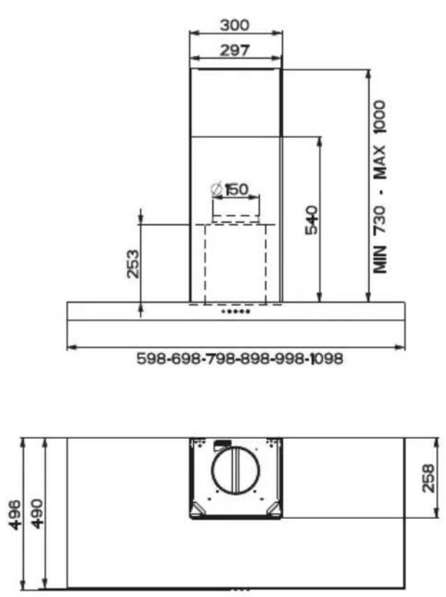
- The minimum safety distance between the cooker top and the extractor hood is 650 mm (some models can be installed at a lower height, please refer to the paragraphs on working dimensions and installation).
- If the instructions for installation for the gas hob specify a greater distance, this must be respected.
- Check that the mains voltage corresponds to that indicated on the rating plate fixed to the inside of the hood.
- Means for disconnection must be incorporated in the fixed wiring in accordance with the wiring rules.
- For Class I appliances, check that the domestic power supply guarantees adequate earthing.
- Connect the extractor to the exhaust flue through a pipe of minimum diameter 120 mm. The route of the flue must be as short as possible.
- Regulations concerning the discharge of air have to be fulfilled.
-
Do not connect the extractor hood to exhaust ducts carrying combustion fumes (boilers, fireplaces, etc.).
-
If the extractor is used in conjunction with non-electrical appliances (e.g. gas burning appliances), a sufficient degree of aeration must be guaranteed in the room in order to prevent the backflow of exhaust gas. When the cooker hood is used in conjunction with appliances supplied with energy other than electric, the negative pressure in the room must not exceed 0,04 mbar to prevent fumes being drawn back into the room by the cooker hood.
- The air must not be discharged into a flue that is used for exhausting fumes from appliances burning gas or other fuels.
- If the supply cord is damaged, it must be replaced from the manufacturer or its service agent.
- Connect the plug to a socket complying with current regulations, located in an accessible place.
- With regards to the technical and safety measures to be adopted for fume discharging it is important to closely follow the regulations provided by the local authorities.
⚠ WARNING: Before installing the Hood, remove the protective films.
- Use only screws and small parts in support of the hood.
⚠ WARNING: Failure to install the screws or fixing device in accordance with these instructions may result in electrical hazards.
- Do not look directly at the light through optical devices (binoculars, magnifying glasses...).
- Do not flambè under the range hood; risk of fire.
- This appliance can be used by children aged from 8 years and above and persons with reduced physical, sensory or mental capabilities or lack of experience and knowledge if they have been given supervision or instruction concerning use of the appliance in a safe way and understand the hazards involved. Children shall not play with the appliance. Cleaning and user maintenance shall not be made by children without supervision.
- Children should be supervised to ensure that they do not play with the appliance.
- The appliance is not to be used by persons (including children) with reduced physical, sensory or mental capabilities, or lack of experience and knowledge, unless they have been given supervision or instruction.
⚠️ Accessible parts may become hot when used with cooking appliances.
- Clean and/or replace the Filters after the specified time period (Fire hazard). See paragraph Care and Cleaning.
- There shall be adequate ventilation of the room when the range hood is used at the same time as appliances burning gas or other fuels (not applicable to appliances that only discharge the air back into the room).
- The symbol 📁 on the product or on its packaging indicates that this product may not be treated as household waste. Instead it shall be handed over to the applicable collection point for the recycling of electrical and electronic equipment. By ensuring this product is disposed of correctly, you will help prevent potential negative consequences for the environment and human health, which could otherwise be caused by inappropriate waste handling of this product. For more detailed information about recycling of this product, please contact your local city office, your household waste disposal service or the shop where you purchased the product.
Dimensions
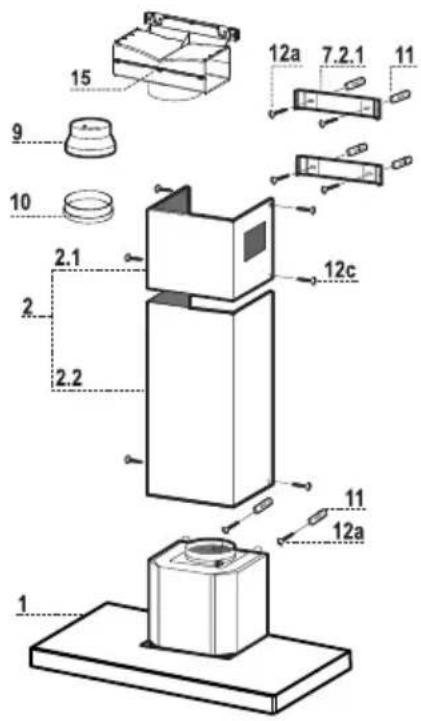
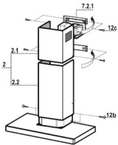
Components
Ref. Q.ty Product Components
1 1 Hood Body, complete with: Controls, Light, Blower, Filters
2 1 Telescopic Chimney comprising:
2.1 1 Upper Section
2.2 1 Lower Section
9 1 Reducer Flange ø 150-120 mm
10 1 Adapting ring ∅ 120-125 mm
15 1 Air Outlet Connection
Ref. Q.ty Installation Components
7.2.1 2 Upper Chimney Section Fixing Brackets
11 6 Wall Plugs
12a 6 Screws 4,2 x 44,4
12c 6 Screws 2,9 x 9,5
Q.ty Documentation
1 Instruction Manual
Wall drilling and bracket fixing
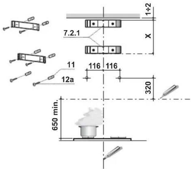
Wall marking:
- Draw a vertical line on the supporting wall up to the ceiling, or as high as practical, at the centre of the area in which the hood will be installed.
- Draw a horizontal line at 650 ~mm above the hob. Place bracket 7.2.1 on the wall as shown about 1 - 2 ~mm from the ceiling or upper limit aligning the centre (notch) with the vertical reference line.
- Mark the wall at the centres of the holes in the bracket.
- Place bracket 7.2.1 on the wall as shown at X mm below the first bracket (X = height of the upper chimney section supplied), aligning the centre (notch) with the vertical line.
- Mark the wall at the centres of the holes in the bracket.
- Mark a reference point as indicated at 116 mm from the vertical reference line and 320 mm above the horizontal reference line.
- Repeat this operation on the other side.
- Drill 8 mm holes at all the centre points marked.
- Insert the wall plugs 11 in the holes.
• Fix the brackets using the 12a (4.2 x 44.4) screws supplied. - Insert the two screws 12a (4,2 x 44,4) supplied in the hood body fixing holes, leaving a gap of 5-6 mm between the wall and the head of the screw.
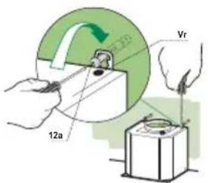
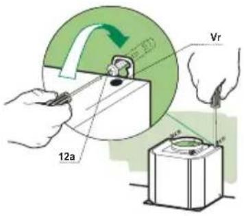
Mounting the hood body
- Before attaching the hood body, tighten the two screws Vr located on the hood body mounting points.
- Hook the hood body onto the screws 12a.
• Fully tighten the support screws 12a. - Adjust the screws Vr to level the hood body.
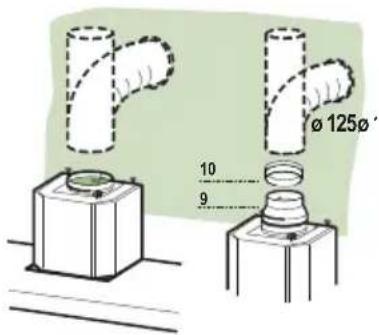
Connections
DUCTED VERSION AIR EXHAUST SYSTEM
When installing the ducted version, connect the hood to the chimney using either a flexible or rigid pipe 150 or 125 mm, the choice of which is left to the installer.
- To install a 125 mm air exhaust connection, insert the reducer flange 9 on the hood body air outlet and the adapting ring 120-125 10 on the reducer flange.
- Fix the pipe in position using sufficient pipe clamps (not supplied).
- Remove any activated charcoal filters.
Exhausted mode Recommendations and suggestions
Connect the extractor to the exhaust flue through a pipe of minimum diameter 125 mm.
The route of the flue must be as short as possible.
Ideal ducting distance to discharge outlet is maximum of 3 meters straight run, or 2 meters and one 90 degree bend preferably rigid duct.
natural_image
Pure architectural line drawing of a staircase with stairs and a curved channel (no text or symbols)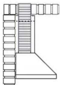
natural_image
Pure architectural line drawing of a staircase with stairs and columns (no text or symbols)Maximum ducting distance should be 3 meters, with one 90 degree bend.
For each additional 90 degree bend, the maximum distance is reduced by 1 meter.
If the ducting is not correct it will increase noise and reduce performance.
AIR OUTLET – RECIRCULATION VERSION
- Unfasten the 2 screws fixing the upper bracket 7.2.1.
- Fasten the air outlet connector 15 in its place, using the 2 screws removed as above.
- Join the Connector 15 to the Hood canopy outlet using a rigid or flexible pipe 150 mm, selection of which is at the discretion of the installation technician.
- Make sure that the Activated charcoal odour filter has been fitted.
ELECTRICAL CONNECTION
- Connect the hood to the mains through a two-pole switch having a contact gap of at least 3 mm.
- Remove the grease filters (see paragraph Maintenance) being sure that the connector of the feeding cable is correctly inserted in the socket placed on the side of the fan.
natural_image
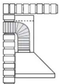
Diagram showing a mechanical component with an inset view of a tool interacting with a green arrow (no text or symbols present)Flue assembly
Upper exhaust flue
- Slightly widen the two sides of the upper flue and hook them behind the brackets 7.2.1, making sure that they are well seated.
- Secure the sides to the brackets by using the 4 screws 12c (2,9 x 9,5) supplied.
- Make sure that the outlet of the extensions pieces is aligned with the chimney outlets.
Lower exhaust flue
- Slightly widen the two sides of the flue and hook them between the upper flue and the wall, making sure that they are well seated.
- Fix the lower part laterally to the hood body by using the 2 screws 12c (2,9 x 9,5) supplied.
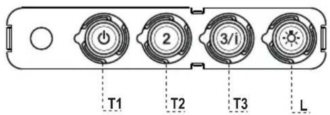
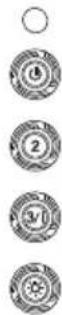
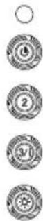
Control panel
BUTTON LED FUNCTIONS
T1 Speed On Turns the Motor on at Speed one.
Turns the Motor off.
T2 Speed On Turns the Motor on at Speed two.
T3 Speed Fixed When pressed briefly, turns the Motor on at Speed three.
Flashing Pressed for 2 Seconds.
Activates Speed four with a timer set to 6 minutes, after which it returns to the speed that was set previously. Suitable to deal with maximum levels of cooking fumes.
L Light Turns the Lighting System on and off.
Warning: Button T1 turns the motor off, after first passing to speed one.
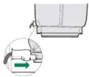
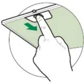
Grease filters
CLEANING METAL SELF- SUPPORTING GREASE FILTERS
- The filters must be cleaned every 2 months of operation, or more frequently for particularly heavy usage, and can be washed in a dishwasher.
- Remove the filters one at a time by pushing them towards the back of the group and pulling down at the same time.
- Wash the filters, taking care not to bend them. Allow them to dry before refitting.
- When refitting the filters, make sure that the handle is visible on the outside.
natural_image
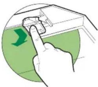
Hand pressing a green arrow on a device component, enclosed in a circular frame (no text or symbols)Activated charcoal filter (Recirculation version)
REPLACING THE ACTIVATED CHARCOAL FILTER
- The filter is not washable and cannot be regenerated, and must be replaced approximately every 4 months of operation, or more frequently for particularly heavy usage.
- Remove the metal grease filters.
- Remove the saturated activated carbon filter by releasing the fixing hooks.
- Fit the new filter by hooking it into its seating.
• Refit the metal grease filters.
natural_image
Illustration of a hand pressing a component on a green surface, with a green arrow indicating direction (no text or symbols)Lighting unit
- For replacement contact technical support ("To purchase contact technical support").

natural_image
Diagram showing a hand pressing down on a mechanical component with an inset magnified view of the handle (no text or symbols)Montage Cheminée
Cheminée supérieure
natural_image
Hand pressing a green arrow on a device component, enclosed in a circular frame (no text or symbols)Filtre anti-odeur (Version filtrante)
REMPLACEMENT FILTRE AU CHARBON ACTIF
natural_image
Illustration of a hand pressing a component on a green surface, with a green arrow indicating direction (no text or symbols)Éclairage
natural_image
Pure architectural line drawing of a staircase with stairs and columns, no text or symbols present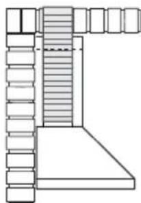
natural_image
Pure architectural line drawing of a staircase with no text or symbolsnatural_image
Diagram showing a mechanical component with a green arrow indicating direction, no text or symbols presentKaminmontage
Oberer Kaminteil

Schalttafel
natural_image
Hand pressing a green arrow on a device component, enclosed in a circular frame (no text or symbols)Geruchsfilter (Umluftversion)
natural_image
Illustration of a hand pressing a component on a green surface, with a green arrow indicating direction (no text or symbols)Beleuchtung
LED-Strahler
Ref. Installatieonderdelen
natural_image
Pure architectural line drawing of a staircase with stairs and a curved arch (no text or symbols)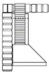
natural_image
Pure architectural line drawing of a staircase with stairs and windows (no text or symbols)natural_image
Diagram showing a mechanical component with a green arrow indicating direction, no text or symbols present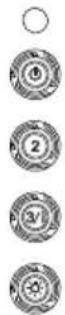
Bedieningspaneel
TOETS LED FUNCTIONS
natural_image
Hand pressing a green arrow on a device component, enclosed in a circular frame (no text or symbols)Geurfilter (filterversie)
VERVANGING FILTER MET ACTIEVE KOOLSTOF
natural_image
Illustration of a hand pressing a component on a green surface, with a green arrow indicating direction (no text or symbols)Verlichting
Ref. Installatieonderdelen
natural_image
Pure architectural line drawing of a staircase with stairs and columns, no text or symbols present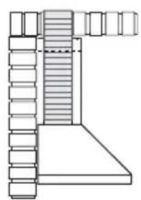
natural_image
Pure architectural line drawing of a staircase with stairs and windows (no text or symbols)natural_image
Diagram showing a hand pressing down on a mechanical component with an inset magnified view of the handle (no text or symbols)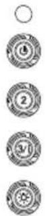
Tablero de mandos
natural_image
Hand pressing a green arrow on a device screen (no text or symbols visible)natural_image
Illustration of a hand pressing a component on a green surface, with a green arrow indicating direction (no text or symbols)Iluminación
natural_image
Two technical line drawings of a mechanical assembly, showing front and side views (no text or symbols)natural_image
Diagram showing a mechanical component with an inset view of a tool interacting with a green arrow (no text or symbols present)Montagem da chaminé

Quadro de comandos
TECLA LED FUNÇÕES
natural_image
Hand pressing a green arrow on a device component, enclosed in a circular frame (no text or symbols)natural_image
Illustration of a hand pressing a component on a green surface, with a green arrow indicating direction (no text or symbols)Iluminação
natural_image
Pure architectural line drawing of a staircase with an arched base and columns (no text or symbols)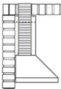
natural_image
Pure architectural line drawing of a staircase with stairs and columns (no text or symbols)natural_image
Diagram showing a mechanical component with a green arrow indicating direction, no text or symbols presentHormin asennus
Ylähormi
Käyttöpaneeli
PAINIKE MERKKIVALO TOIMINNOT
natural_image
Hand pressing a green arrow on a device component, enclosed in a circular frame (no text or symbols)natural_image
Illustration of a hand pressing a component on a green surface, with a green arrow indicating direction (no text or symbols)Valaistus
Clarence Street, Royal Leamington Spa,
Warwickshire, CV31 2AD, England.
Tel: +44 (0) 1926 457400 Fax: +44 (0) 1926 450526
E-mail: consumers@rangemaster.co.uk
www.rangemaster.co.uk
Falcon is a business name of AGA RANGEMASTER GROUP PLC


- SOMMAIRE
- FR
- INHALTSVERZEICHNIS
- DE
- Montaggio Camino
- Camino superiore
- Quadro comandi
- TASTO LED FUNZIONI
- Filtro antiodore (Versione Filtrante)
- SOSTITUZIONE FILTRO ANTIODORE AL CARBONE ATTIVO
- Illuminazione
- Components
- Ref. Q.ty Product Components
- Ref. Q.ty Installation Components
- Q.ty Documentation
- Wall drilling and bracket fixing
- Wall marking:
- Mounting the hood body
- Connections
- DUCTED VERSION AIR EXHAUST SYSTEM
- Exhausted mode Recommendations and suggestions
- AIR OUTLET – RECIRCULATION VERSION
- ELECTRICAL CONNECTION
- Flue assembly
- Upper exhaust flue
- Lower exhaust flue
- Control panel
- BUTTON LED FUNCTIONS
- Grease filters
- CLEANING METAL SELF- SUPPORTING GREASE FILTERS
- Activated charcoal filter (Recirculation version)
- REPLACING THE ACTIVATED CHARCOAL FILTER
- Lighting unit
- Montage Cheminée
- Cheminée supérieure
- Filtre anti-odeur (Version filtrante)
- REMPLACEMENT FILTRE AU CHARBON ACTIF
- Éclairage
- Kaminmontage
- Oberer Kaminteil
- Geruchsfilter (Umluftversion)
- Beleuchtung
- LED-Strahler
- Ref. Installatieonderdelen
- Bedieningspaneel
- TOETS LED FUNCTIONS
- Geurfilter (filterversie)
- VERVANGING FILTER MET ACTIEVE KOOLSTOF
- Verlichting
- Iluminación
- Montagem da chaminé
- Quadro de comandos
- TECLA LED FUNÇÕES
- Iluminação
- Hormin asennus
- Ylähormi
- Käyttöpaneeli
- PAINIKE MERKKIVALO TOIMINNOT
- Valaistus
Brand : FALCON
Model : FHDSF1100BL
Category : Range hood