
FEXT720 - Range hood FALCON - Free user manual and instructions
Find the device manual for free FEXT720 FALCON in PDF.


| Product type | Wall-mounted hood |
| Brand | Falcon |
| Model | FEXT720 |
| Dimensions (W x D x H) | 60 x 50 x 70 cm |
| Weight | 12 kg |
| Power supply | 220-240 V, 50 Hz |
| Maximum extraction power | 650 m³/h |
| Maximum noise level | 55 dB |
| Filters | Washable aluminum grease filter, optional activated charcoal filter |
| Lighting | 2 x LED |
| Controls | Touch control panel with digital display |
| Energy class | A+ |
| Material | Stainless steel |
| Functions | 3 speeds + intensive mode, recirculation function possible, delayed automatic shut-off |
| Maintenance and cleaning | Regular cleaning of the grease filter (in dishwasher or by hand), replacement of the charcoal filter every 3 to 6 months |
| Safety | Automatic shut-off in case of overheating, filter saturation indicator |
| Repairability index | 8/10 |
| Available spare parts | Filters, LED bulbs, remote control (if applicable) |
| Warranty | 2 years |
| General information | European manufacturing, professional installation recommended |
Frequently Asked Questions - FEXT720 FALCON
User questions about FEXT720 FALCON
0 question about this device. Answer the ones you know or ask your own.
Ask a new question about this device
Download the instructions for your Range hood in PDF format for free! Find your manual FEXT720 - FALCON and take your electronic device back in hand. On this page are published all the documents necessary for the use of your device. FEXT720 by FALCON.
USER MANUAL FEXT720 FALCON
natural_image
Technical line drawing of a kitchen range hood with ventilation slots and mounting brackets (no text or symbols)| IT | Libretto Istruzioni |
| GB | Instruction Manual |
| FR | Manuel d’Instructions |
| DE | Bedienungsanleitung |
| NL | Gebruiksaanwijzing |
Gentile Signora, Caro Signore,
natural_image
Illustration of a microwave oven with a green laser emitting vapor, no text or symbols present
natural_image
Illustration of a laboratory setup with a beaker, a steaming pot, and a flame (no text or symbols)Ingombro

Componenti

natural_image
Technical line drawing of a mechanical device with internal components and a hand symbol (no text or labels)Tipo Cappa 54 72
L2 515 695


Connessioni
USCITA ARIA VERSIONE ASPIRANTE
natural_image
Illustration of a medical device with green internal components and a blue rectangular body, no text or symbols present.MANUTENZIONE
Filtri antigrasso
PULIZIA FILTRI ANTIGRASSO METALLICI
natural_image
Illustration of hands performing a task on a green striped material, with a green arrow indicating the motion direction (no text or symbols present)SOSTITUZIONE FILTRO ANTIODORE AL CARBONE ATTIVO
natural_image
Illustration of a hand holding a coiled fist with a green handle, next to a small vehicle (no text or symbols)Dear Customer,
If you follow the recommendations contained in this Instruction Manual, your appliance will give you constant high performance and will remain efficient for many years to come.
CONTENTS
| RECOMMENDATIONS AND SUGGESTIONS 12 |
| CHARACTERISTICS 13 |
| INSTALLATION 14 |
| USE 16 |
| MAINTENANCE 17 |
INSTALLATION
- The manufacturer will not be held liable for any damages resulting from incorrect or improper installation.
- The minimum safety distance between the cooker top and the extractor hood is 650 mm.
- Check that the mains voltage corresponds to that indicated on the rating plate fixed to the inside of the hood.
- For Class I appliances, check that the domestic power supply guarantees adequate earthing.
Connect the extractor to the exhaust flue through a pipe of minimum diameter 120 mm. The route of the flue must be as short as possible.
- Do not connect the extractor hood to exhaust ducts carrying combustion fumes (boilers, fireplaces, etc.).
- If the extractor is used in conjunction with non-electrical appliances (e.g. gas burning appliances), a sufficient degree of aeration must be guaranteed in the room in order to prevent the backflow of exhaust gas. The kitchen must have an opening communicating directly with the open air in order to guarantee the entry of clean air.
USE
- The extractor hood has been designed exclusively for domestic use to eliminate kitchen smells.
- Never use the hood for purposes other than for which it has been designed.
- Never leave high naked flames under the hood when it is in operation.
- Adjust the flame intensity to direct it onto the bottom of the pan only, making sure that it does not engulf the sides.
- Deep fat fryers must be continuously monitored during use: overheated oil can burst into flames.
- The hood should not be used by children or persons not instructed in its correct use.
MAINTENANCE
- Switch off or unplug the appliance from the mains supply before carrying out any maintenance work.
- Clean and/or replace the Filters after the specified time period.
- Clean the hood using a damp cloth and a neutral liquid detergent.


natural_image
Illustration of a microwave oven with a green X-shaped exhaust plume and a gas stove emitting green smoke (no text or symbols)
natural_image
Illustration of a laboratory setup with a beaker, green liquid, and dark material on a stand, crossed by a green X-shaped line (no text or symbols)Dimensions

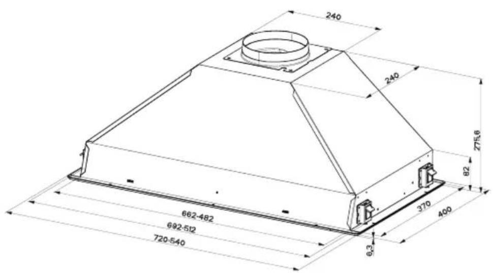
Components
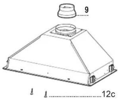
Ref. Q.ty Product Components
1 1 Hood Body, complete with: Controls, Light, Blower, Filters
9 1 Reducer Flange ∅ 150-120 mm
Ref. Q.ty Installation Components
12c 2 Screws 2,9 x 6,5
Q.ty Documentation
1 Instruction Manual
1 Electric Diagram
Drilling the Support surface and Fitting the Hood
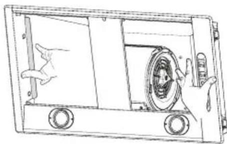
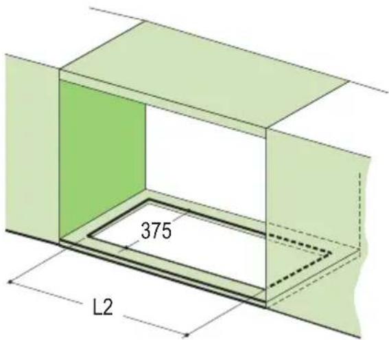
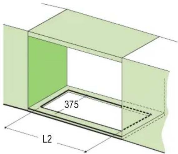
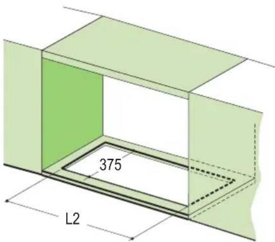
The Hood can be fitted directly to the underside of the Wall units (min. 650 mm above the cooker top) with snap-on side supports, which are set up for a support panel thickness of between 15 mm and 30 mm.
- Cut a fitted opening in the bottom surface of the wall unit, as shown.
- Remove the metal grease filters (see par. on Maintenance).
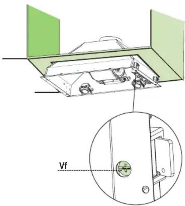
- Disconnect the filter support by turning the internal handles provided.
- Insert the hood until the side supports snap into place.
- Lock in position by tightening the screws Vf from underneath the hood.
natural_image
Technical line drawing of a mechanical device with internal components and a hand gesture (no text or symbols)Hood Type 54 72
L2 515 695


- Replace the filter support
- Screw the filter support using the 2 screws 12c (2,9 x 6,5) provided.
- Replace the grease filters make sure that the handle is visible on the outside.

natural_image
Technical line drawing of a mechanical device with a circular inset showing a dimension labeled '12c' (no text or symbols beyond basic geometry)Connections
DUCTED VERSION AIR EXHAUST SYSTEM
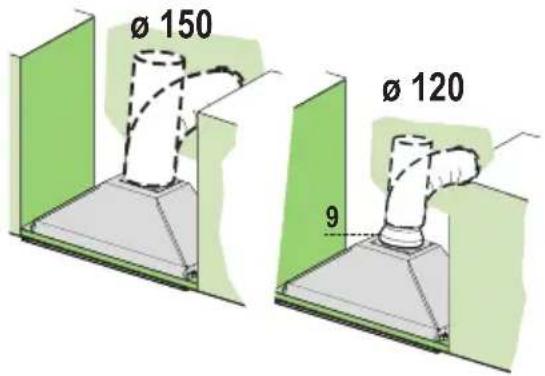
When installing the ducted version, connect the hood to the chimney using either a flexible or rigid pipe 150 or 120 mm, the choice of which is left to the installer.
- To install a 120 mm air exhaust connection, insert the reducer flange 9 on the hood body outlet.
- Fix the pipe in position using sufficient pipe clamps (not supplied).
- Remove any activated charcoal filters.
RECIRCULATION VERSION AIR OUTLET
- Drill a hole 120 or 150mm in the shelf above the hood and connect the hood canopy outlet to the top part of the wall unit by means of a rigid or flexible pipe of the same diameter, the choice of which is at the discretion of the installer.
- To install a 120 mm air exhaust connection, insert the reducer flange 9 on the hood body outlet.
- Fix the pipe in position using sufficient pipe clamps (not supplied).
- Ensure that the activated charcoal filters have been inserted.

ELECTRICAL CONNECTION
- Connect the hood to the mains through a two-pole switch having a contact gap of at least 3 mm.
Control Panel
The hood can be switched on pushing directly onto the requested speed without firstly having to select 0/1 button.
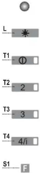
| KEY | LED | FUNCTIONS | |
| L | 0/1 Light Turns lighting on and off. | ||
| T1 | 0/1 Motor on First speed. | When pressed for about 2 seconds the motor is switched off. | |
| T2 | Speed on Second speed. | ||
| T3 | Speed on Third speed. | ||
| T4 | Speed Fixed Max. speed | ||
| Flashing | Intensive speed. S | uitable for the strongest cooking vapours and odours. The function becomes active when the button is pushed for about 2 seconds. After 10 minutes of functioning turns off automatically. This function can be interrupted by means of pressing any of the buttons. | |
| S1 | Led | Fixed | Indicates that the Metal grease filters saturation alarm has been triggered, and the filters need to be washed. The alarm is triggered after 100 working hours. (Reset; check the Maintenance-paragraph) |
| Flashing | indicates that the activated charcoal odour filter saturation alarm has been triggered, and the filter has to be replaced; the metal grease filters must also be washed. The activated charcoal odour filter is triggered after 200 working hours. (Activation and Reset; check the Maintenance-paragraph) | ||
REMOTE CONTROL (OPTIONAL)
The appliance can be controlled using a remote control powered by a 1.5 V carbon-zinc alkaline batteries of the standard LR03-AAA type.
- Do not place the remote control near to heat sources.
• Used batteries must be disposed of in the proper manner.

natural_image
Illustration of a handheld device with green internal components and a white rectangular body, no text or symbols present.MAINTENANCE
Grease filters
CLEANING METAL GREASE FILTERS
Alarm signal reset
- Switch of the lights and extractor motor.
- Press button T3 for at least 3 seconds, until the leds start to flash.
Cleaning the filters
- The filters are washable and must be cleaned when led S1 flashes or at least every 2 months of operation, or more frequently for particularly heavy usage.
- Remove the filters one at a time, supporting them with one hand and turning the safety knobs (pull and turn).
- Wash the filters, taking care not to bend them. Allow them to dry before refitting.
- Replace them and fix them using the safety knobs provided (pull and turn).

natural_image
Illustration of hands performing a finger manipulation technique on a green striped material (no text or symbols)REPLACING THE ACTIVATED CHARCOAL FILTER
- The filter is not washable and cannot be regenerated. It must be replaced when led S1 flashes or at least every 4 months. The alarm signal will only light up when the extractor motor is switched on.
Alarm signal reset
- Switch off the lights and extractor motor.
- Press button T3 for at least 3 seconds, until the leds start to flash.
Replacing the Filter
- Remove the grease filters.
- Remove the saturated activated charcoal filters as shown (A).
• Fit new filters (B). - Replace the grease filters.
Alarm signal activation
- In Recirculation version Hoods, the Filter saturation alarm can be enabled on installation or at a later date.
• Turn the Lights and the suction Motor off. - Disconnect the Hood using the Main switch or the double-pole switch on the mains power supply.
- Restore the connection by pressing and holding T1.
- Release the button. All five LEDs are turned on
- Within 3 seconds press T1 until LEDs T1 and T4 flash in confirmation: LED flashes twice - Activated charcoal filter saturation alarm ENABLED LED flashes once - Activated charcoal filter saturation alarm DISABLED
Lighting
LIGHT REPLACEMENT
50 W halogen light.
- Remove the 2 screws fixing the light cover.
- Remove the lamp by gripping the protruding part and turning to the left.
- Replace with a new lamp with the same characteristics, making sure that you insert the two pins properly into their housings.
- Replace the cover and fix it in position using the two screws removed as above

natural_image
Illustration of a hand holding a small ring with a green handle, next to an open mobile phone (no text or symbols present)Chère Madame, Cher Monsieur,

natural_image
Illustration of a kitchen appliance with a green X-shaped mark and a steaming dish, no text or symbols present.
natural_image
Illustration of a laboratory setup with a beaker, heating dish, and smokestack (no text or symbols)Encombrement

Composants

natural_image
Technical line drawing of a mechanical device with internal components and a hand operating the door (no text or symbols)Type de Hotte 54 72
L2 515 695
natural_image
Technical line drawing of a door frame with an inset close-up showing a dimension labeled '125' (no text or symbols beyond the label)Branchements
SORTIE AIR VERSION ASPIRANTE
natural_image
Illustration of a handheld device with green internal components and a blue rectangular base (no text or symbols)ENTRETIEN
natural_image
Illustration of hands performing a task on a green striped material, with a green arrow indicating the motion direction (no text or symbols present)Filtre anti-odeur (Version filtrante)
REPLACEMENT FILTRE AU CHARBON ACTIF
natural_image
Illustration of a hand holding a ring with a green handle, next to a small bus (no text or symbols present)natural_image
Illustration of a kitchen appliance with a green X-shaped mark and a steaming pot nearby (no text or symbols)
natural_image
Illustration of a laboratory setup with a beaker and a flame, crossed by a green X-shaped line (no text or symbols)Platzbedarf

Komponenten

natural_image
Technical line drawing of a mechanical device with internal components and a hand operating it (no text or symbols)Hauben-typ 54 72
L2 515 695

natural_image
Illustration of a medical device with green internal components and a blue rectangular device (no text or symbols)WARTUNG
Fettfilter
METALLFETTFILTER REINIGUNG
natural_image
Illustration of hands performing a finger manipulation technique on a green striped material (no text or symbols)natural_image
Illustration of a kitchen appliance with a green X-shaped mark and a steaming pot nearby (no text or symbols)
natural_image
Illustration of a laboratory setup with a beaker, green liquid, and dried plant material under a test tube (no text or symbols)Buitenafmetingen
Onderdelen

Ref. Productonderdelen
Ref. Installatieonderdelen
12c 2 Schroeven 2,9 x 6,5
Documentatie
natural_image
Technical line drawing of a mechanical device with internal components and a bird silhouette (no text or symbols)Type wasemkap 54 72
L2 515 695

natural_image
Illustration of a handheld device with green internal components and a white casing, showing no text or symbols.ONDERHOUD
Vetfilters
REINIGING VAN DE METALEN VETFILTERS
natural_image
Illustration of hands performing a finger manipulation technique on a green striped surface (no text or symbols)VERVANGING FILTER MET ACTIEVE KOOLSTOF
natural_image
Illustration of a hand holding a ring with a green ring and a small car above it, enclosed in a circle (no text or symbols)The symbol on the product or on its packaging indicates that this product may not be treated as household waste. Instead it shall be handed over to the applicable collection point for the recycling of electrical and electronic equipment. By ensuring this product is disposed of correctly, you will help prevent potential negative consequences for the environment and human health, which could otherwise be caused by inappropriate waste handling of this product. For more detailed information about recycling of this product, please contact your local city office, your household waste disposal service or the shop where you purchased the product.


- Componenti
- Connessioni
- USCITA ARIA VERSIONE ASPIRANTE
- MANUTENZIONE
- Filtri antigrasso
- PULIZIA FILTRI ANTIGRASSO METALLICI
- SOSTITUZIONE FILTRO ANTIODORE AL CARBONE ATTIVO
- INSTALLATION
- USE
- MAINTENANCE
- Components
- Ref. Q.ty Product Components
- Ref. Q.ty Installation Components
- Q.ty Documentation
- Drilling the Support surface and Fitting the Hood
- Connections
- DUCTED VERSION AIR EXHAUST SYSTEM
- RECIRCULATION VERSION AIR OUTLET
- ELECTRICAL CONNECTION
- Control Panel
- REMOTE CONTROL (OPTIONAL)
- Grease filters
- CLEANING METAL GREASE FILTERS
- Alarm signal reset
- Cleaning the filters
- REPLACING THE ACTIVATED CHARCOAL FILTER
- Replacing the Filter
- Alarm signal activation
- Lighting
- LIGHT REPLACEMENT
- W halogen light.
- Composants
- Branchements
- SORTIE AIR VERSION ASPIRANTE
- ENTRETIEN
- Filtre anti-odeur (Version filtrante)
- REPLACEMENT FILTRE AU CHARBON ACTIF
- Komponenten
- WARTUNG
- Fettfilter
- METALLFETTFILTER REINIGUNG
- Onderdelen
- Ref. Productonderdelen
- Ref. Installatieonderdelen
- Documentatie
- ONDERHOUD
- Vetfilters
- REINIGING VAN DE METALEN VETFILTERS
- VERVANGING FILTER MET ACTIEVE KOOLSTOF
Brand : FALCON
Model : FEXT720
Category : Range hood