
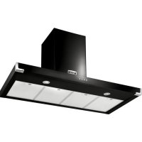
LEIHDC90SL - Range hood FALCON - Free user manual and instructions
Find the device manual for free LEIHDC90SL FALCON in PDF.
| Product type | Range hood |
| Brand | FALCON |
| Model | LEIHDC90SL |
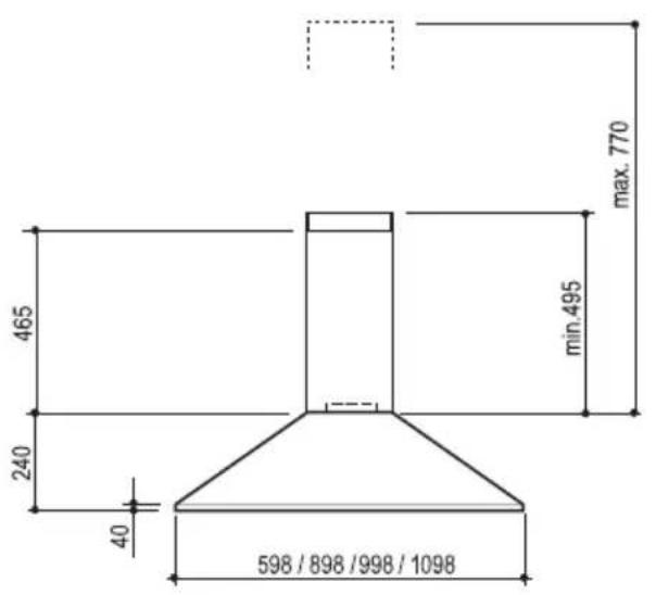
| Width | 90 cm (898 mm) |
| Depth | 465 mm (estimated from the dimension diagram) |
| Hood body height | 240 mm (estimated) |
| Total height with telescopic chimney | From 495 mm to 770 mm (adjustable) |
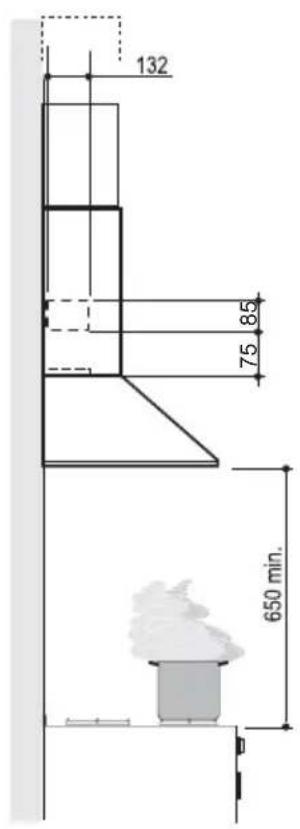
| Minimum safety distance above cooking surface | 650 mm |
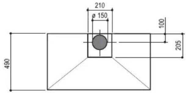
| Air outlet diameter | 150 mm (reducible to 125 mm or 120 mm) |
| Installation types | Ducted or recirculating |
| Number of speeds | 3 (low, medium, high) |
| Lighting | Integrated (L button to turn on/off) |
| Filter type | Washable metal grease filters (dishwasher safe) + replaceable activated charcoal filter |
| Cleaning frequency of grease filters | About every 2 months (more often with heavy use) |
| Replacement frequency of charcoal filter | About every 4 months (not washable) |
| Power supply | 220-240 V, 50 Hz (check the rating plate) |
| Appliance class | Class I (mandatory grounding) |
| Power cord type | Internal connector (replacement by professional) |
| Materials | Metal (likely stainless steel) |
| Weight | Not specified (estimated 15-20 kg) |
| Included accessories | Telescopic chimney, mounting flanges, screws, plugs, diameter reducer |
| Available spare parts | Grease filters, charcoal filters, bulbs (if applicable) |
| Repairability | Replacement of filters and bulbs by user; other repairs by professional |
Frequently Asked Questions - LEIHDC90SL FALCON
User questions about LEIHDC90SL FALCON
0 question about this device. Answer the ones you know or ask your own.
Ask a new question about this device
Download the instructions for your Range hood in PDF format for free! Find your manual LEIHDC90SL - FALCON and take your electronic device back in hand. On this page are published all the documents necessary for the use of your device. LEIHDC90SL by FALCON.
USER MANUAL LEIHDC90SL FALCON
natural_image
Line drawing of a 3D architectural structure resembling a chimney or canopy (no text or symbols)Libretto di Istruzioni Instructions Manual Manuel d'Instructions Bedienungsanleitung Gebruiksaanwijzing Manual de instrucciones Manual de Instruções Käyttöohje
INDICE
IT
SAFETY INFORMATION......17
CHARACTERISTICS 20
INSTALLATION....21
USE 27
CARE AND CLEANING....28
SOMMAIRE
FR
CONSIGNES DE SÉCURITÉ....30
CARACTERISTIQUES....33
INSTALLATION....34
UTILISATION 40
NETTOYAGE ET ENTRETIEN 41
INHALTSVERZEICHNIS
DE
natural_image
Line drawing of a conical metal frame with two hands pointing to a square opening (no text or symbols)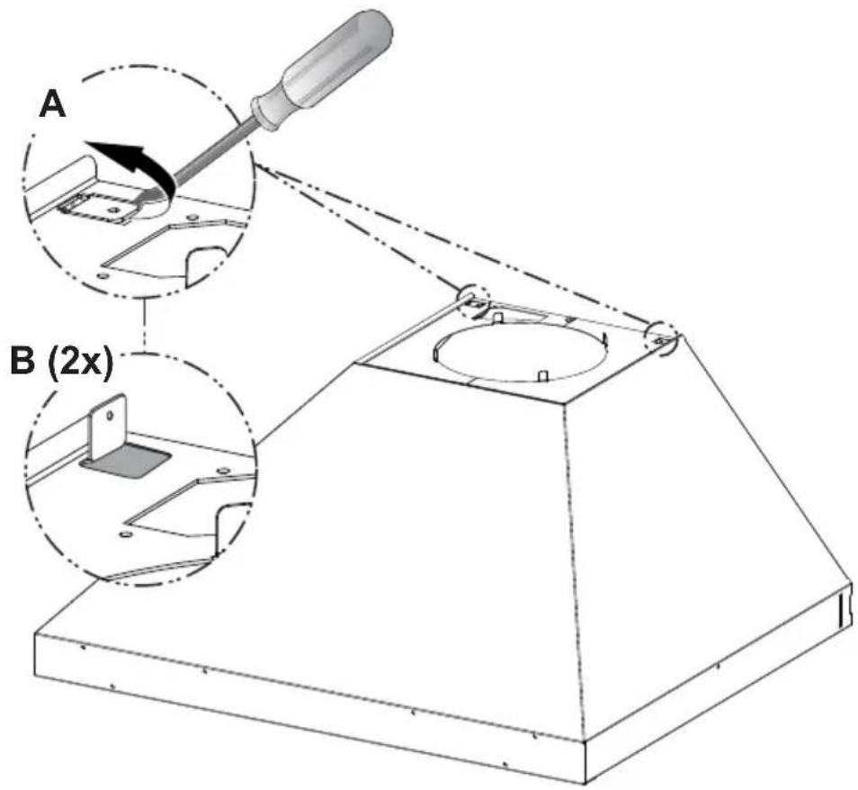
natural_image
Pure architectural or mechanical diagram showing a staircase with stairs and columns, no text or symbols present.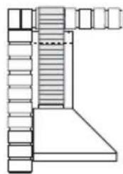
natural_image
Pure architectural line drawing of a staircase with stairs and windows (no text or symbols)natural_image
Diagram showing a mechanical component with a highlighted section and directional arrow (no text or symbols)Montaggio Camino
Camino superiore
natural_image
Hand inserting a green arrow on a device screen, enclosed in a circular frame (no text or symbols)Filtri antigrasso
PULIZIA FILTRI ANTIGRASSO METALLICI
natural_image
Illustration of hands performing a finger manipulation technique on a striped fabric (no text or symbols)Filtro antiodore (Versione Filtrante)
SOSTITUZIONE FILTRO ANTIODORE AL CARBONE ATTIVO
natural_image
Technical diagram of a mechanical component with internal parts and directional arrows indicating flow or movement (no text or symbols present)Illuminazione
natural_image
Illustration of two hands holding a small object, one with a curved arrow and the other a circular ring (no text or symbols)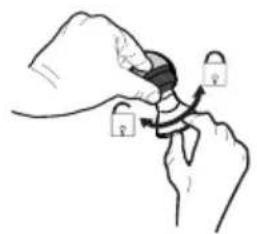
natural_image
Illustration of a hand holding a padlock with arrows indicating motion (no text or symbols)| Lampada | Assorbimento (W) | Attacco Voltaggio (V) | Dimensione (mm) | Codice ILCOS | |
 | 4 E14 220 | -240 107 x 37 | DRBB/F-4-220-240-E14-35/100 | ||
 | 5 GU10 230 | 52 x 50 | DRPAR-5/840-220/240-GU10-35/36DRPAR-5/830-220/240-GU10-35/36 |
For your safety and correct operation of the appliance, read this manual carefully before installation and use. Always keep these instructions with the appliance even if you move or sell it. Users must fully know the operation and safety features of the appliance.
The wire connection has to be done by specialized technician.
- The manufacturer will not be held liable for any damages resulting from incorrect or improper installation.
- The minimum safety distance between the cooker top and the extractor hood is 650 mm (some models can be installed at a lower height, please refer to the paragraphs on working dimensions and installation).
- If the instructions for installation of the gas hob specify a greater distance, this must be respected.
- Check that the mains voltage corresponds to that indicated on the rating plate fixed to the inside of the hood.
- Means for disconnection must be incorporated in the fixed wiring in accordance with the wiring rules.
- For Class I appliances, check that the domestic power supply guarantees adequate earthing.
- Connect the extractor to the exhaust flue through a pipe of minimum diameter 120 mm. The route of the flue must be as short as possible.
- Regulations concerning the discharge of air have to be fulfilled.
-
Do not connect the extractor hood to exhaust ducts carrying combustion fumes (boilers, fireplaces, etc.).
-
If the extractor is used in conjunction with non-electrical appliances (e.g. gas burning appliances), a sufficient degree of aeration must be guaranteed in the room in order to prevent the backflow of exhaust gas. When the cooker hood is used in conjunction with appliances supplied with energy other than electric, the negative pressure in the room must not exceed 0,04 mbar to prevent fumes being drawn back into the room by the cooker hood.
- The air must not be discharged into a flue that is used for exhausting fumes from appliances burning gas or other fuels.
- If the supply cord is damaged, it must be replaced from the manufacturer or its service agent.
- Connect the plug to a socket complying with current regulations, located in an accessible place.
- With regards to the technical and safety measures to be adopted for fume discharging it is important to closely follow the regulations provided by the local authorities.
⚠ WARNING: Before installing the Hood, remove the protective films.
- Use only screws and small parts supplied with the hood.
⚠ WARNING: Failure to install the screws or fixing device in accordance with these instructions may result in electrical hazards.
- Do not look directly at the light through optical devices (binoculars, magnifying glasses...).
- Do not flambè under the range hood; risk of fire.
- This appliance can be used by children aged from 8 years and above and persons with reduced physical, sensory or mental capabilities or lack of experience and knowledge if they have been given supervision or instruction concerning use of the appliance in a safe way and understand the hazards involved. Children shall not play with the appliance. Cleaning and user maintenance shall not be made by children without supervision.
- Children should be supervised to ensure that they do not play with the appliance.
- The appliance is not to be used by persons (including children) with reduced physical, sensory or mental capabilities, or lack of experience and knowledge, unless they have been given supervision or instruction.
⚠️ Accessible parts may become hot when used with cooking appliances.
- Clean and/or replace the Filters after the specified time period (Fire hazard). See paragraph Care and Cleaning.
- There shall be adequate ventilation of the room when the range hood is used at the same time as appliances burning gas or other fuels (not applicable to appliances that only discharge the air back into the room).
- The symbol 📁 on the product or on its packaging indicates that this product may not be treated as household waste. Instead it shall be handed over to the applicable collection point for the recycling of electrical and electronic equipment. By ensuring this product is disposed of correctly, you will help prevent potential negative consequences for the environment and human health, which could otherwise be caused by inappropriate waste handling of this product. For more detailed information about recycling of this product, please contact your local city office, your household waste disposal service or the shop where you purchased the product.

"In case of replacement with halogen lamp use only self-shielded tungsten halogen lamps or self-shielded metal halide lamps."
Dimensions
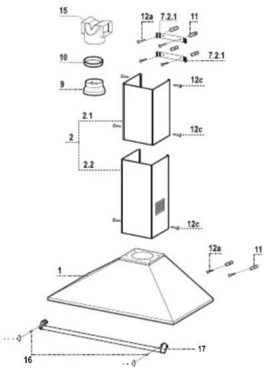
Components
Ref. Q.ty Product Components
1 1 Hood Body, complete with: Controls, Light, Blower, Filters
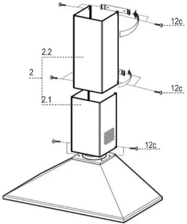
2 1 Telescopic Chimney comprising:
2.1 1 Upper Section
2.2 1 Lower Section
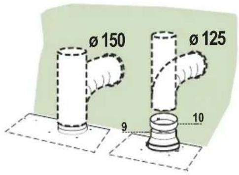
9 1 Reducer Flange ø 150-120 mm
10 1 Adapting ring ∅ 120-125 mm
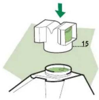
15 1 Air Outlet Connection
Ref. Q.ty Installation Components
7.2.1 2 Upper Chimney Section Fixing Brackets
11 6 Wall Plugs
12a 6 Screws 4.2 x 44,4
12c 6 Screws 2.9 x 9.5
16 2 Screws M5 x 16 (Optional)
17 1 Styling rail (Optional)
18 2 Cap (Optional)
Q.ty Documentation
1 Instruction Manual
Wall drilling and bracket fixing
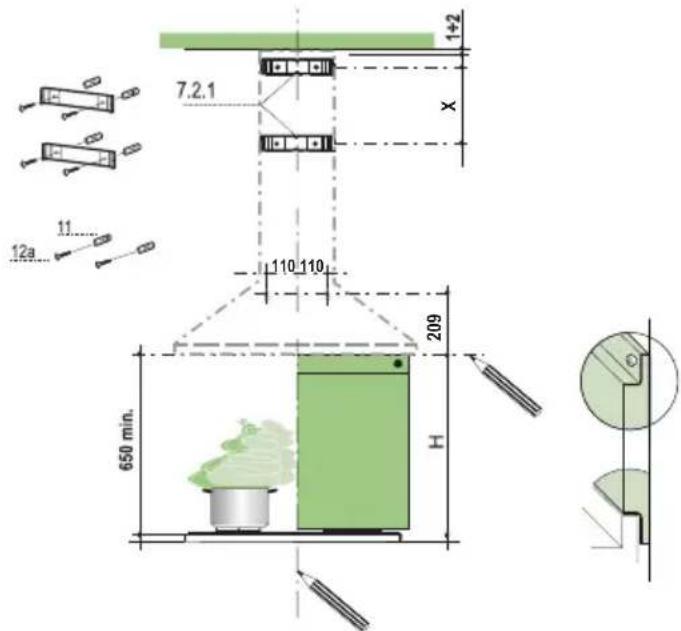
Wall marking:
- Draw a vertical line on the supporting wall up to the ceiling, or as high as practical, at the centre of the area in which the hood will be installed.
- Draw a horizontal line at 650 mm above the hob for installation without the back panel, or at height H (height of the visible part of the panel) for installation with the back panel.
- Place bracket 7.2.1 on the wall as shown about 1-2 mm from the ceiling or upper limit aligning the centre (notch) with the vertical reference line.
- Mark the wall at the centres of the holes in the bracket.
- Place bracket 7.2.1 on the wall as shown at X mm below the first bracket (X = height of the upper chimney section supplied), aligning the centre (notch) with the vertical line.
- Mark the wall at the centres of the holes in the bracket.
- Mark a reference point on the horizontal reference line as indicated, 110 mm from the vertical reference line and 209 mm above the horizontal reference line.
- Repeat this operation on the other side.
- Drill 8 mm holes at all the centre points marked.
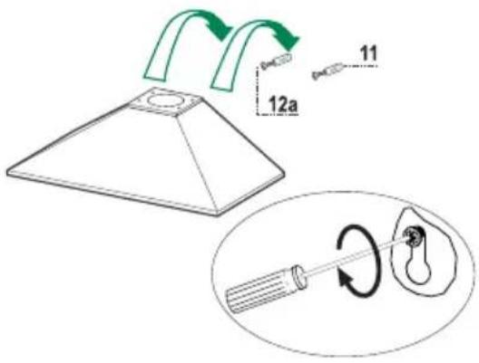
- Insert the wall plugs 11 in the holes.
• Fix the brackets using the 12a (4,2 x 44,4) screws supplied. - Insert the two screws 12a (4,2 x 44,4) supplied in the hood body fixing holes, leaving a gap of 5-6 mm between the wall and the head of the screw.
REAR PANEL (OPTIONAL)
The Rear Panel must be fitted before fixing the hood body and, for both upper and lower position fixing, must be fitted at the correct height prior to installing the bases. As this operation is rather complex, it should be carried out either by the kitchen installer or a qualified person who knows the final dimensions of the units.
For the upper fixing position, proceed as follows:
- Mark the centres of the two holes in the upper plate.
- Drill 8 mm holes at all the centre points marked.
- Insert the wall plugs 11 in the holes.
• Fix the brackets using the 12a screws supplied. - Fix the back panel (where present) using the 12a screws supplied.
- Rest the back panel on the base, inserting the lower plate between the upper surface and the wall, centring it on the vertical reference line.
natural_image
Line drawing of a conical metal frame with two hands pointing to a square opening (no text or symbols)

flowchart
graph TD
    A["Start"] --> B["Add Component"]
    B --> C["Add Ring"]
    C --> D["Add Petri Dish"]
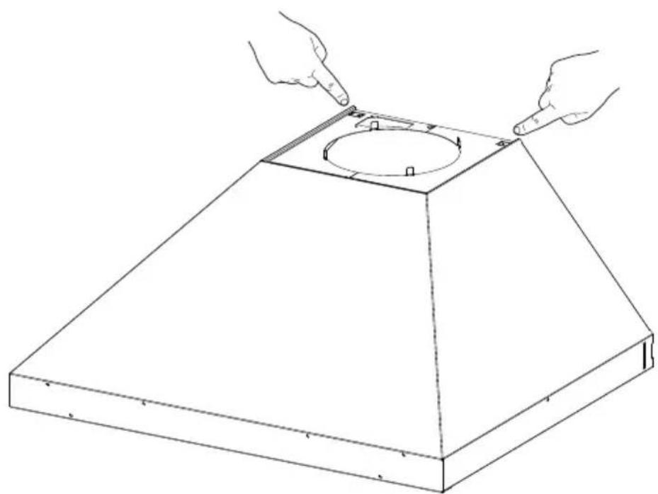
Mounting the hood body
- Hook the hood body onto the screws 12a.
• Fully tighten the support screws 12a.
Connections
DUCTED VERSION AIR EXHAUST SYSTEM
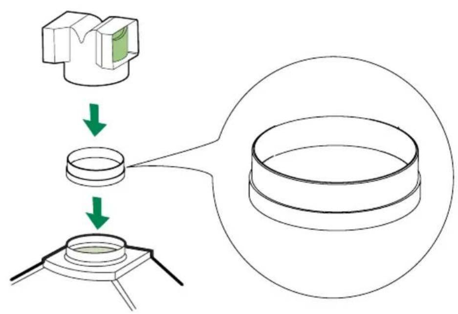
When installing the ducted version, connect the hood to the chimney using either a flexible or rigid pipe 150 or 125 mm, the choice of which is left to the installer.
- To install a 125 mm air exhaust connection, insert the reducer flange 9 on the hood body air outlet and the adapting ring 120-125 10a on the reducer flange.
- Fix the pipe in position using sufficient pipe clamps (not supplied).
- Remove any activated charcoal filters.
Exhausted mode Recommendations and suggestions
Connect the extractor to the exhaust flue through a pipe of minimum diameter 125 mm.
The route of the flue must be as short as possible.
Ideal ducting distance to discharge outlet is maximum of 3 meters straight run, or 2 meters and one 90 degree bend preferably rigid duct.
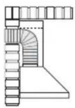
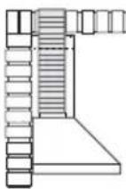
Maximum ducting distance should be 3 meters, with one 90 degree bend.
For each additional 90 degree bend, the maximum distance is reduced by 1 meter.
If the ducting is not correct it will increase noise and reduce performance.
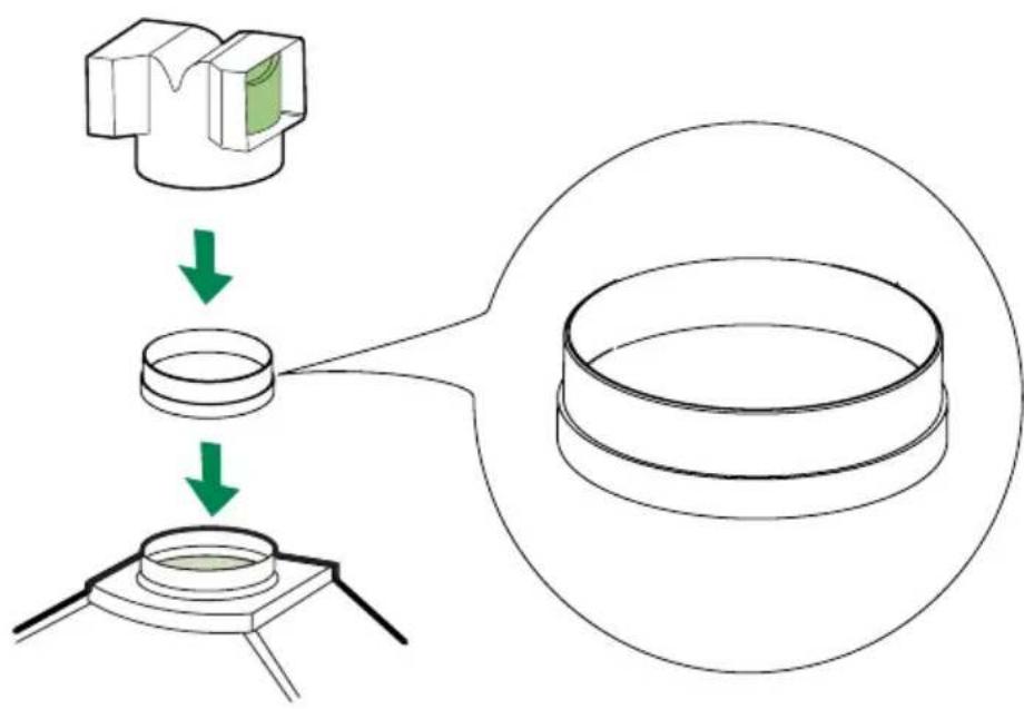
RECIRCULATION VERSION AIR OUTLET
- Push fit the air outlet fitting 15 onto the air outlet of the hood body.
- Ensure that the activated charcoal filters have been inserted.
ELECTRICAL CONNECTION
- Connect the hood to the mains through a two-pole switch having a contact gap of at least 3 ~mm .
- Remove the grease filters (see paragraph Maintenance) being sure that the connector of the feeding cable is correctly inserted in the socket placed on the side of the fan.
natural_image
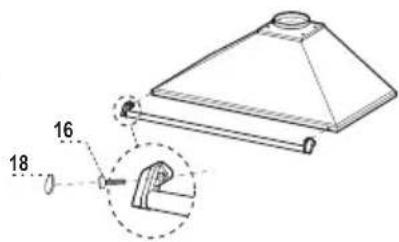
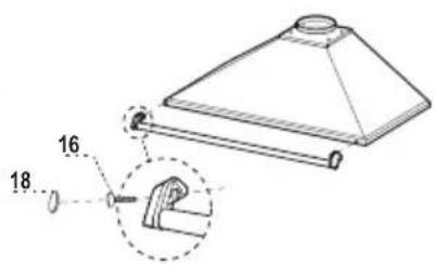
Diagram showing a mechanical component with an inset view of a green arrow indicating direction (no text or symbols present)- Position the Utensil rail on the front part of the hood.
• Fix using the Utensil rail to the hood using the Screws 16. - Insert the plugs 18.
Flue assembly
Upper exhaust flue
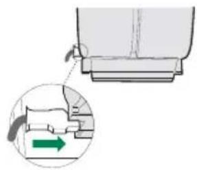
- Slightly widen the two sides of the upper flue and hook them behind the brackets 7.2.1, making sure that they are well seated.
- Secure the sides to the brackets using the 4 screws 12c (2,9 x 9,5) supplied.
Lower exhaust flue
- Slightly widen the two sides of the flue and hook them between the upper flue and the wall, making sure that they are well seated.
- Fix the lower part laterally to the hood body using the 2 screws 12c (2,9 x 9,5) supplied.
- On the recirculation version, fit the directional grids 8a - 8b in their housings making sure that the directional symbols are towards the top and front of the hood. Also make sure that they are correctly inserted in the connection extension pieces 14.1.
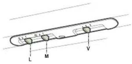
L Light Switches the lighting system on and off
M Motor Switches the extractor motor on and off
V Speed Sets the operating speed of the extractor:
- Low speed, used for a continuous and silent air change in the presence of light cooking vapour.
- Medium speed, suitable for most operating conditions given the optimum treated air flow/noise level ratio.
- Maximum speed, used for eliminating the highest cooking vapour emission, including long periods.
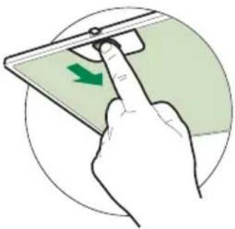
Grease filters
CLEANING METAL SELF-SUPPORTING GREASE FILTERS
- The filters must be cleaned every 2 months of operation, or more frequently for particularly heavy usage, and can be washed in a dishwasher.
- Remove the filters one at a time by pushing them towards the back of the group and pulling down at the same time.
- Wash the filters, taking care not to bend them. Allow them to dry before refitting.
- When refitting the filters, make sure that the handle is visible on the outside.
natural_image
Hand inserting a green arrow on a device screen, enclosed in a circular frame (no text or symbols)Grease filters
CLEANING METAL GREASE FILTERS
The filters are washable at least every 2 months of operation, or more frequently for particularly heavy usage.
- Remove the filters one at a time by supporting them with one hand and turning the safety knobs (pull and turn).
- Wash the filters, taking care not to bend them. Allow them to dry before refitting.
- Refit them and fix them using the safety knobs provided (pull and turn).
natural_image
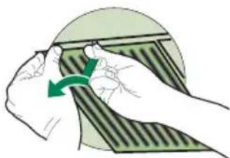
Illustration of hands performing a finger manipulation technique on a striped fabric (no text or symbols)Activated charcoal filter (Recirculation version)
REPLACING THE ACTIVATED CHARCOAL FILTER
- The filter is not washable and cannot be regenerated, and must be replaced approximately every 4 months of operation, or more frequently for particularly heavy usage.
- Remove the metal grease filters.
- Remove the saturated activated carbon filter by releasing the fixing hooks.
- Fit the new filter by hooking it into its seating.
- Refit the metal grease filters.
natural_image
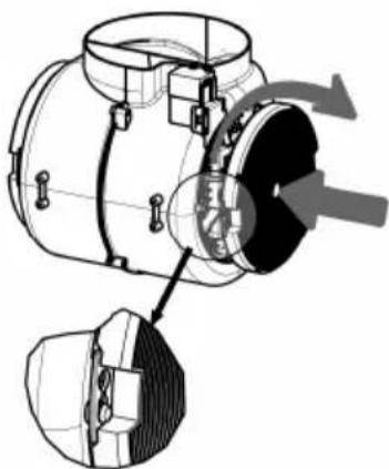
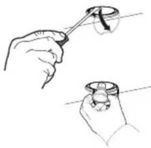
Technical diagram of a mechanical device with internal components and directional arrows indicating flow or movement (no text or symbols present)Lighting unit
REPLACING OF THE LED UNIT
LED
- To remove the lighting unit a screwdriver can be used in order to slightly press the side part of the unit.
- Remove the unit, remove the electrical connector and replace the unit with a new one. ("To purchase contact technical support")
natural_image
Illustration of two hands holding a small object, one with a curved arrow and the other a circular object (no text or symbols)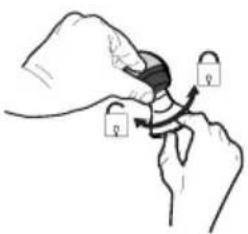
natural_image
Illustration of a hand holding a padlock with arrows indicating movement (no text or symbols)| Lamp Power (W) Socket Voltage (V) Dimension (mm) ILC OS Code | |||||
| [1XW64] | 4 E14 220-240 107 x 37 DRBB/F-4-220-240-E14-35/100 | ||||
 | 5 | GU10 | 230 | 52 x 50 | DRPAR-5/840-220/240-GU10-35/36DRPAR-5/830-220/240-GU10-35/36 |
FIXATION EMBASE (SI FOURNIE)
natural_image
Line drawing of a conical metal frame with two hands pointing to a square opening (no text or symbols)

Montage Corps Hotte
Connexions
SORTIE DE L'AIR EN VERSION EVACUATION
natural_image
Technical line drawing of a mechanical assembly with two views (left and right), showing internal components and structural details without any text or symbols.natural_image
Diagram showing a mechanical component with an inset view of a green arrow indicating direction (no text or symbols present)Montage Cheminée
Cheminée supérieure
natural_image
Hand inserting a green arrow on a device screen, enclosed in a circular frame (no text or symbols)natural_image
Illustration of hands performing a finger manipulation technique on a striped fabric (no text or symbols)Filtre anti-odeur (Version filtrante)
REPLACEMENT FILTRE AU CHARBON ACTIF
natural_image
Technical diagram of a mechanical device with internal components and directional arrows indicating flow or movement (no text or symbols present)Valaistus
LAMPPUJEN VAIHTO
Led-valo
natural_image
Illustration of two hands holding a small object, one with a curved arrow and the other a ring (no text or symbols)
natural_image
Illustration of a hand holding a padlock with arrows indicating movement (no text or symbols)| Ampoule Absorption (W) Culot Voltage (V) Dimensions (mm) Code ILCOS | |||||
| [204H] | 4 E14 220-240 107 x | 37 DRBB/F-4-220-240-E14-35/100 | |||
 | 5 GU10 230 | 52 x 50 | DRPAR-5/840-220/240-GU10-35/36DRPAR-5/830-220/240-GU10-35/36 | ||
RÜCKWANDPANEEL (OPTION)
natural_image
Line drawing of a conical metal frame with two hands pointing to a square opening (no text or symbols)

flowchart
graph TD
    A["Start"] --> B["Add Component"]
    B --> C["Add Ring"]
    C --> D["Add Petri Dish"]
Anschlüsse
LUFTAUSTRITT BEI DER ABSAUGVERSION
natural_image
Diagram showing a mechanical component with a highlighted section and directional arrow (no text or symbols)Kaminmontage
Oberer Kaminteil
natural_image
Hand inserting a green arrow on a device screen, enclosed in a circular frame (no text or symbols)Fettfilter
METALLFETTFILTER REINIGUNG
natural_image
Illustration of hands performing a finger manipulation technique with green arrows indicating motion (no text or symbols)Geruchsfilter (Umluftversion)
natural_image
Technical diagram of a mechanical device with internal components and directional arrows indicating motion (no text or symbols)Beleuchtung
AUSWECHSELN DER LAMPE
LED-Strahler
natural_image
Illustration of two hands holding a small object, one with a curved arrow indicating motion (no text or symbols)
natural_image
Illustration of a hand holding a padlock with arrows indicating movement (no text or symbols)Ref. Installatieonderdelen
MUURPLAAT (OPTIONEEL)
natural_image
Line drawing of a conical metal frame with two hands pointing to a square opening (no text or symbols)

Montage van de Wasemkap
Aansluitingen
LUCHTUITGANG – AANZUIGENDE UITVOERING
natural_image
Technical line drawing of a mechanical assembly with two views (left and right), showing internal components and structural elements without any text or symbols.natural_image
Diagram showing a mechanical component with a green arrow indicating direction, no text or symbols presentMontage keukenrail
natural_image
Hand inserting a green arrow on a device screen, enclosed in a circular frame (no text or symbols)Vetfilters
REINIGING VAN DE METALEN VETFILTERS
natural_image
Illustration of hands performing a mechanical or structural manipulation task with a green arrow indicating rotation (no text or symbols present)Geurfilter (filterversie)
VERVANGING FILTER MET ACTIEVE KOOLSTOF
natural_image
Technical diagram of a mechanical device with internal components and directional arrows indicating flow or movement (no text or symbols present)Verlichting
VERVANGEN VAN DE LAMPEN
Ledlampje
natural_image
Illustration of two hands holding a small object, one with a curved arrow and the other a circular cap (no text or symbols)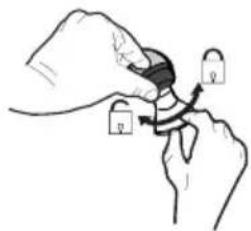
| Lamp Stroomopname (W) Aansluiting Voltage (V) Afmeting (mm) ILCOS-code | |||||
| [CKDA] | 4 E14 220-240 107 x 37 DRBB/F-4-220-240-E14-35/100 | ||||
 | 5 GU10 230 | 52 x 50 | DRPAR-5/840-220/240-GU10-35/36DRPAR-5/830-220/240-GU10-35/36 | ||
natural_image
Line drawing of a conical metal frame with two hands pointing to a square opening (no text or symbols)
flowchart
graph TD
    A["Start"] --> B["Add Component"]
    B --> C["Add Ring"]
    C --> D["Add Petri Dish"]
natural_image
Diagram showing a mechanical component with a highlighted section and directional arrow (no text or symbols)natural_image
Hand inserting a green arrow on a device screen, enclosed in a circular frame (no text or symbols)Filtros antigrasa
LIMPIEZA DE LOS FILTROS ANTIGRASA LABERINTO
natural_image
Illustration of hands performing a sewing or cutting operation on a striped garment (no text or symbols)natural_image
Technical diagram of a mechanical device with internal components and directional arrows indicating flow or movement (no text or symbols present)Iluminación
SUSTITUCION DE LAS LAMPARAS
Foco led
natural_image
Illustration of two hands holding a small object, one with a curved arrow and the other a ring (no text or symbols)
natural_image
Illustration of a hand holding a padlock with arrows indicating movement (no text or symbols)| Lámpara Consumo de energía (W) Casquillo Voltaje (V) Dimensión (mm) Código ILCOS | |||||
| [THAW] | 4 E14 220-240 | 107 x 37 DR | BB/F-4-220-240 | E14-35/100 | |
 | 5 GU10 | 230 | 52 x 50 | DRPAR-5/840-220/240-GU10-35/36DRPAR-5/830-220/240-GU10-35/36 | |
natural_image
Line drawing of a conical metal frame with two hands pointing to a square opening (no text or symbols)

flowchart
graph TD
    A["Start"] --> B["Add Component"]
    B --> C["Add Ring"]
    C --> D["Add Petri Dish"]
natural_image
Diagram showing a mechanical component with an arrow indicating direction, no text or symbols present• Coloque as tampas 18.
Montagem da chaminé
Chaminé superior
natural_image
Hand inserting a green arrow on a device screen, enclosed in a circular frame (no text or symbols)Filtros antigordura
LIMPEZA DOS FILTROS ANTIGORDURA
natural_image
Illustration of hands performing a finger manipulation technique on a striped fabric (no text or symbols)natural_image
Technical diagram of a mechanical device with internal components and a close-up view of a component (no text or symbols)Iluminação
natural_image
Illustration of two hands holding a small object, one with a curved arrow and the other a ring (no text or symbols)
natural_image
Illustration of hands holding keys with a curved arrow indicating movement (no text or symbols)natural_image
Line drawing of a conical metal frame with two hands pointing to a square opening (no text or symbols)

Liitännät
ILMAN ULOSTULO IMUVERSIOSSA
natural_image
Two technical diagrams showing mechanical assembly or structural components, no text or symbols presentnatural_image
Diagram showing a mechanical component with an arrow indicating direction, no text or symbols presentHormin kokoaminen
Ylempi hormi
natural_image
Hand inserting a green arrow on a device screen, enclosed in a circular frame (no text or symbols)Rasvasuodattimet
METALLISTEN RASVASUODATTIMIEN PUHDISTUS
natural_image
Illustration of hands performing a finger manipulation technique with green arrows indicating motion (no text or symbols)natural_image
Technical diagram of a mechanical device with internal components and directional arrows indicating flow or movement (no text or symbols present)Valaistus
LAMPPUJEN VAIHTO
Led-valo
natural_image
Illustration of two hands holding a small object, one with a curved arrow and the other a ring (no text or symbols)
natural_image
Illustration of hands holding keys with arrows indicating movement (no text or symbols)| Lamppu Ottoteho (W) Kanta Jännite (V) Koko (mm) ILCOS-koodi | |||||
 | 4 E14 220-240 107 x 37 | DRBB/F-4-220-240-E14-35/100 | |||
| [14772] | 5 GU10 230 52 x 50 | DRPAR-5/840-220/240-GU10-35/36DRPAR-5/830-220/240-GU10-35/36 | |||
AGA RANGEMASTER GROUP PLC
Clarence Street, Royal Leamington Spa,
Warwickshire, CV31 2AD, England.
Tel: +44 (0) 1926 457400 Fax: +44 (0) 1926 450526
E-mail: consumers@rangemaster.co.uk
www.rangemaster.co.uk
Falcon is a business name of AGA RANGEMASTER GROUP PLC


- INDICE
- SOMMAIRE
- INHALTSVERZEICHNIS
- Montaggio Camino
- Camino superiore
- Filtri antigrasso
- PULIZIA FILTRI ANTIGRASSO METALLICI
- Filtro antiodore (Versione Filtrante)
- SOSTITUZIONE FILTRO ANTIODORE AL CARBONE ATTIVO
- Illuminazione
- Components
- Ref. Q.ty Product Components
- Ref. Q.ty Installation Components
- Q.ty Documentation
- Wall drilling and bracket fixing
- Wall marking:
- REAR PANEL (OPTIONAL)
- Mounting the hood body
- Connections
- DUCTED VERSION AIR EXHAUST SYSTEM
- Exhausted mode Recommendations and suggestions
- RECIRCULATION VERSION AIR OUTLET
- ELECTRICAL CONNECTION
- Flue assembly
- Upper exhaust flue
- Lower exhaust flue
- Grease filters
- CLEANING METAL SELF-SUPPORTING GREASE FILTERS
- CLEANING METAL GREASE FILTERS
- Activated charcoal filter (Recirculation version)
- REPLACING THE ACTIVATED CHARCOAL FILTER
- Lighting unit
- REPLACING OF THE LED UNIT
- LED
- FIXATION EMBASE (SI FOURNIE)
- Montage Corps Hotte
- Connexions
- SORTIE DE L'AIR EN VERSION EVACUATION
- Montage Cheminée
- Cheminée supérieure
- Filtre anti-odeur (Version filtrante)
- REPLACEMENT FILTRE AU CHARBON ACTIF
- Valaistus
- LAMPPUJEN VAIHTO
- Led-valo
- RÜCKWANDPANEEL (OPTION)
- Anschlüsse
- LUFTAUSTRITT BEI DER ABSAUGVERSION
- Kaminmontage
- Oberer Kaminteil
- Fettfilter
- METALLFETTFILTER REINIGUNG
- Geruchsfilter (Umluftversion)
- Beleuchtung
- AUSWECHSELN DER LAMPE
- LED-Strahler
- Ref. Installatieonderdelen
- MUURPLAAT (OPTIONEEL)
- Montage van de Wasemkap
- Aansluitingen
- LUCHTUITGANG – AANZUIGENDE UITVOERING
- Montage keukenrail
- Vetfilters
- REINIGING VAN DE METALEN VETFILTERS
- Geurfilter (filterversie)
- VERVANGING FILTER MET ACTIEVE KOOLSTOF
- Verlichting
- VERVANGEN VAN DE LAMPEN
- Ledlampje
- Filtros antigrasa
- LIMPIEZA DE LOS FILTROS ANTIGRASA LABERINTO
- Iluminación
- SUSTITUCION DE LAS LAMPARAS
- Foco led
- Montagem da chaminé
- Chaminé superior
- Filtros antigordura
- LIMPEZA DOS FILTROS ANTIGORDURA
- Iluminação
- Liitännät
- ILMAN ULOSTULO IMUVERSIOSSA
- Hormin kokoaminen
- Ylempi hormi
- Rasvasuodattimet
- METALLISTEN RASVASUODATTIMIEN PUHDISTUS
- AGA RANGEMASTER GROUP PLC
Brand : FALCON
Model : LEIHDC90SL
Category : Range hood