DTB10003 - Irrigation timer Toolland - Free user manual and instructions
Find the device manual for free DTB10003 Toolland in PDF.
| Product type | Battery sprayer |
| Brand | Toolland |
| Model | DTB10003 |
| Tank capacity | 12 L |
| Weight | 3.5 kg |
| Tank dimensions | 345 x 180 x 490 mm |
| Power supply | Li-ion battery 12 V, 2500 mAh |
| Charging time | 150 min |
| Runtime | 100 min |
| Tank material | PE, PP, ABS |
| Lance material | Stainless steel |
| Hose length | 120 cm |
| Color | Orange |
| Spray type | Adjustable (narrow jet to mist) |
| Safety | Eye protection recommended; do not use in explosive atmosphere |
| Maintenance | Clean with soft cloth and mild detergent; do not immerse |
| Storage | Empty tank, remove battery, store in a clean, dry place |
| Warranty | 24 months on manufacturer defects (conditions apply) |
Frequently Asked Questions - DTB10003 Toolland
User questions about DTB10003 Toolland
0 question about this device. Answer the ones you know or ask your own.
Ask a new question about this device
Download the instructions for your Irrigation timer in PDF format for free! Find your manual DTB10003 - Toolland and take your electronic device back in hand. On this page are published all the documents necessary for the use of your device. DTB10003 by Toolland.
USER MANUAL DTB10003 Toolland
natural_image
White agricultural sprayer with orange cover and yellow handle, no visible text or symbols on the device itself.USER MANUAL 3
HANDLEIDING 10
MODE D'EMPLOI 17
MANUAL DEL USUARIO 24
text_image
Exploded view diagram of a washing machine with numbered parts for identificationUSER MANUAL
1. Introduction
To all residents of the European Union
Important environmental information about this product
This symbol on the device or the package indicates that disposal of the device after its lifecycle could harm the environment. Do not dispose of the unit (or batteries) as unsorted municipal waste; it should be taken to a specialized company for recycling. This device should be returned to your distributor or to a local recycling service. Respect the local environmental rules.
If in doubt, contact your local waste disposal authorities.
Thank you for choosing Toolland! Please read the manual thoroughly before bringing this device into service. If the device was damaged in transit, do not install or use it and contact your dealer.
2. Safety Instructions

Read and understand this manual and all safety signs before using this appliance.
Wear face protection (e.g. safety goggles) against the spraying agents.
Date of manufacture.
- This device can be used by children aged from 8 years and above, and persons with reduced physical, sensory or mental capabilities or lack of experience and knowledge if they have been given supervision or instruction concerning the use of the device in a safe way and understand the hazards involved. Children shall not play with the device. Cleaning and user maintenance shall not be made by children without supervision.
Work Area Safety
- Keep your work area clean and well-lit. Cluttered or dark areas invite accidents.
- Do not operate power tools in explosive atmospheres, such as in the presence of flammable liquids, gases or dust. Power tools create sparks which may ignite the dust or fumes.
- Keep children and bystanders away while operating a power tool. Distractions can cause you to lose control.
Electrical Safety
- Avoid body contact with earthed or grounded surfaces, such as pipes, radiators, ranges and refrigerators. There is an increased risk of electric shock if your body is earthed or grounded.
- Do not expose power tools to rain or wet conditions. Water entering a power tool will increase the risk of electric shock.
Personal Safety
- Stay alert, watch what you are doing and use common sense when operating a power tool. Do not use a power tool while you are tired or under the influence of drugs, alcohol or medication. A moment of inattention while operating power tools may result in serious personal injury.
- Use personal protective equipment. Always wear eye protection. Protective equipment such as a dust mask, non-skid safety shoes, hard hat or hearing protection used for appropriate conditions will reduce personal injuries.
- Prevent unintentional starting. Ensure the switch is in the off-position before connecting to power source and/or battery pack, picking up or carrying the tool.
- Carrying power tools with your finger on the switch or energising power tools that have the switch on invites accidents.
- Do not overreach. Keep proper footing and balance at all times. This enables better control of the power tool in unexpected situations.
- Dress properly. Do not wear loose clothing or jewellery. Keep your hair and clothing away from moving parts. Loose clothes, jewellery or long hair can be caught in moving parts.
- Do not let familiarity gained from frequent use of tools allow you to become complacent and ignore tool safety principles. A careless action can cause severe injury within a fraction of a second.
Power Tool Use and Care
- Do not force the power tool. Use the correct power tool for your application. The correct power tool will do the job better and safer at the rate for which it was designed.
- Do not use the power tool if the switch does not turn it on and off. Any power tool that cannot be controlled with the switch is dangerous and must be repaired.
- Disconnect the plug from the power source and/or remove the battery pack, if detachable, from the power tool before making any adjustments, changing accessories, or storing power tools. Such preventive safety measures reduce the risk of starting the power tool accidentally.
- Store idle power tools out of the reach of children and do not allow persons unfamiliar with the power tool or these instructions to operate the power tool.
- Power tools are dangerous in the hands of untrained users.
- Maintain power tools and accessories. Check for misalignment or binding of moving parts, breakage of parts and any other condition that may affect the power tool's operation. If damaged, have the power tool repaired before use.
- Many accidents are caused by poorly maintained power tools.
- Use the power tool, accessories and tool bits etc. in accordance with these instructions, taking into account the working conditions and the work to be performed. Use of the power tool for operations different from those intended could result in a hazardous situation.
- Keep handles and grasping surfaces dry, clean and free from oil and grease.
- Slippery handles and grasping surfaces do not allow for safe handling and control of the
Service
- Have your power tool serviced by a qualified repair person using only identical replacement parts. This will ensure that the safety of the power tool is maintained.
3. General Guidelines
- Refer to the Velleman ^® Service and Quality Warranty on the last pages of this manual.
- All modifications of the device are forbidden for safety reasons. Damage caused by user modifications to the device is not covered by the warranty.
- Only use the device for its intended purpose. Using the device in an unauthorised way will void the warranty.
- Damage caused by disregard of certain guidelines in this manual is not covered by the warranty and the dealer will not accept responsibility for any ensuing defects or problems.
- Nor Velleman Group nv nor its dealers can be held responsible for any damage (extraordinary, incidental or indirect) – of any nature (financial, physical...) arising from the possession, use or failure of this product.
- Keep this manual for future reference.
4. Overview
Refer to the illustrations on page 2 of this manual.
| 1 | cap |
| 2 | cap O-ring |
| 3 | valve |
| 4 | filter |
| 5 | connector |
| 6 | O-ring for connector |
| 7 | pipe tube |
| 8 | inlet water filter |
| 9 | screw |
| 10 | tank |
| 11 | cover |
| 12 | O-ring in cover |
| 13 | plastic nut |
| 14 | clamp |
| 15 | water inlet hose |
| 16 | water pump clip |
| 17 | shock pad |
| 18 | water pump |
| 19 | nut |
| 20 | shock pad |
| 21 | hose |
| 22 | lance |
| 23 | gasket |
| 24 | back cap |
| 25 | screw |
| 26 | screw |
| 27 | clip for circuit board |
| 28 | circuit board compartment |
| 29 | battery compartment |
| 30 | nut |
| 31 | switch cover |
| 32 | Li-ion battery |
| 33 | battery compartment cover |
| 34 | squab |
| 35 | screw |
| 36 | screw |
| 37 | strap |
5. Charging the Battery
- Remove the battery from the battery compartment and connect to the charger.
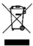
- Connect the charger to the mains. The LED will burn red to indicate the battery is charging.
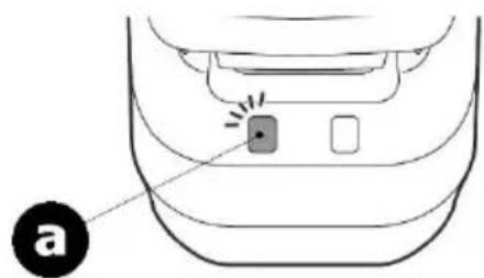
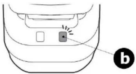
- When the LED burns green, the battery is fully charged. Disconnect the charger from the mains to avoid overcharging. Install the battery in the battery compartment.
natural_image
Diagram of a car interior showing a button and two buttons with a label 'a' pointing to the bottom (no text or symbols on the diagram itself)a
battery is charging
natural_image
Diagram of a car interior showing a button and indicator lights (no text or symbols)b
battery fully charged
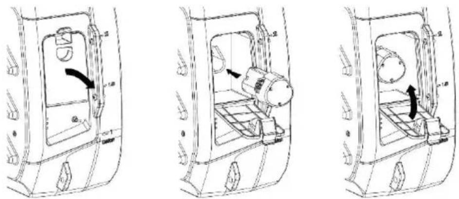
6. Assembly
- Open the battery compartment, install the fully-charged battery and close the compartment.
natural_image
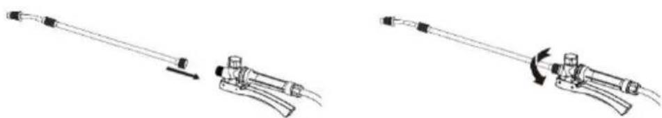
Three technical line drawings of a vehicle interior frame with internal components and directional arrows (no text or symbols)- Screw the lance onto the trigger.
natural_image
Illustration of a medical or laboratory device being adjusted, showing two sequential steps with no text or symbols.7. Operation
- Make sure the pressure sprayer is correctly assembled.
- Open the cap.
- Pour the liquid into the tank and close the cap.
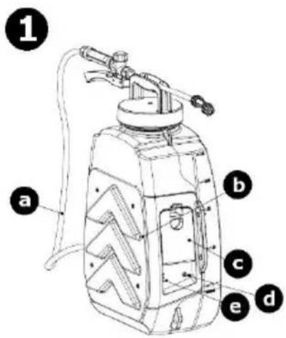
text_image
1 a b c e d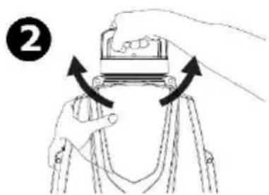
natural_image
Illustration of hands operating a mechanical device with arrows indicating rotation (no text or symbols)
text_image
③| a | hose |
| b | squab |
| c | battery compartment cover |
| d | on-off switch |
| e | power indicator |
- Make sure the lance is firmly screwed onto the trigger. Switch on the pressure sprayer and press the trigger to release the spray.
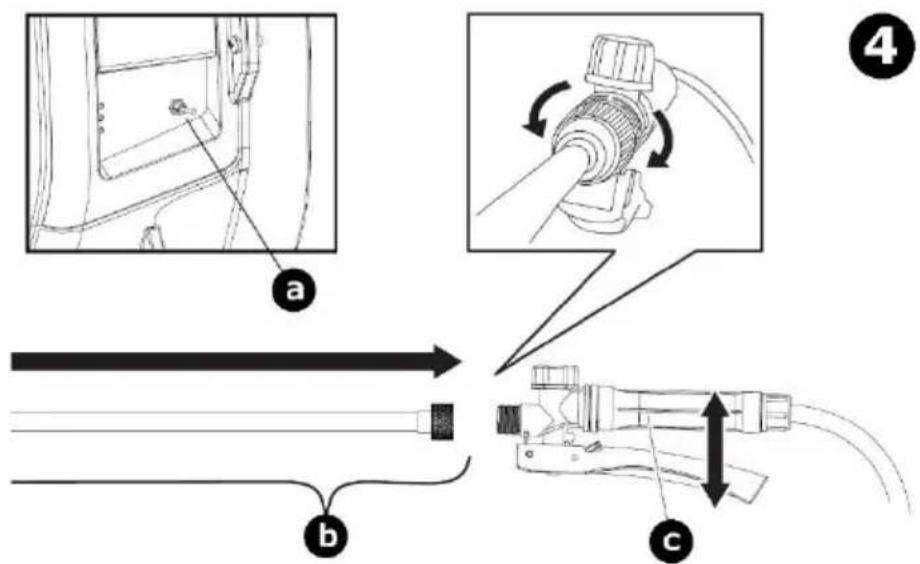
text_image
Technical diagram illustrating cable installation steps with labeled components and directional arrows| a | on-off switch |
| b | lance |
| c | trigger |
- Turn the spray nozzle to adjust the spray width.
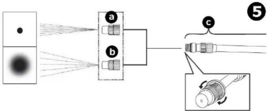
flowchart
graph LR
    A["Source"] --> B["Lens a"]
    A --> C["Lens b"]
    B --> D["Fiber"]
    C --> D
    D --> E["Fiber"]
    style A fill:#f9f,stroke:#333
    style B fill:#ccf,stroke:#333
    style C fill:#ccf,stroke:#333
    style D fill:#cfc,stroke:#333
    style E fill:#fcc,stroke:#333
| a | direct spray |
| b | wide spray |
| c | lance |
8. Troubleshooting
| Problem | Possible cause | Possible solution |
| The appliance does not start after being switched on. | The battery is out of power. | Fully charge the battery. |
| The power switch is damaged. | The appliance is damaged.Please dispose of within the local rules. | |
| The appliance does not spray when the trigger is pressed. | The filter is clogged. | Take out the filter and clean it. |
9. Care and Maintenance
Cleaning
- Do not clean the appliance in the presence of naked flames.
- Before doing any cleaning, remove any spraying agent from the tank, depressurize, switch off the appliance and remove the battery.
- Wipe all exterior surfaces of the appliance clean with a soft cloth dampened with a soap and water solution. Do not immerse or submerge any part of the appliance in water or any other liquid. Never use solvents or cleaning agents containing petroleum (petrol, kerosene, oil), paint thinner, turpentine, alcohol, or ammonia.
Maintenance
- This appliance cannot be repaired and should be scrapped according to the local environmental rules when damaged.
Storage
- Remove the battery from the appliance before storing. Keep the battery in a clean and dry area.
- Remove any spraying agent from the tank before storing.
• Store the appliance and its accessories in a clean and dry area. - Ensure that the appliance is stored in a safe place where unauthorised persons cannot access it.
10. Technical Specifications
battery....Li-ion 2500 mAh voltage....12 V current....1.6 A charger....12 V, 1.5 A working time....100 min. charging time....150 min. tank material....PE - PP - ABS lance material....stainless steel colour....orange tank dimensions....345 x 180 x 490 mm tank volume....12 L hose length....120 cm weight....3.5 kg optional spare battery....DTB10003SP (not incl.)
Use this device with original accessories only. Velleman Group nv cannot be held responsible in the event of damage or injury resulting from (incorrect) use of this device. For more info concerning this product and the latest version of this manual, please visit our website www.velleman.eu. The information in this manual is subject to change without prior notice.
© COPYRIGHT NOTICE
The copyright to this manual is owned by Velleman Group nv. All worldwide rights reserved. No part of this manual may be copied, reproduced, translated or reduced to any electronic medium or otherwise without the prior written consent of the copyright holder.
HANDLEIDING
1. Inleiding
natural_image
Diagram of a car interior showing a button and a labeled point 'a' (no text or symbols beyond the label)a
natural_image
Line drawing of a car's rear bumper with a highlighted button and label 'b' (no text or symbols on the diagram itself)b
natural_image
Three technical line drawings of a vehicle interior frame with internal components and directional arrows (no text or symbols)natural_image
Illustration of a medical or laboratory device being adjusted, showing a lever and adjustment mechanism (no text or symbols)7. Gebruik
natural_image
Illustration of hands operating a mechanical device with arrows indicating rotation (no text or symbols)
text_image
③text_image
Technical diagram illustrating cable installation steps with labeled components and directional arrowsnatural_image
Diagram of a car interior showing a button and two buttons with a pointer, labeled 'a' (no text or symbols beyond the label)a
natural_image
Diagram of a car's rear bumper with a highlighted square and directional arrows, labeled 'b' (no text or symbols on the diagram itself)b
natural_image
Technical line drawing of a vehicle door panel with handle and side-mounted buttons (no text or symbols)
natural_image
Technical line drawing of a mechanical device with no visible text or symbols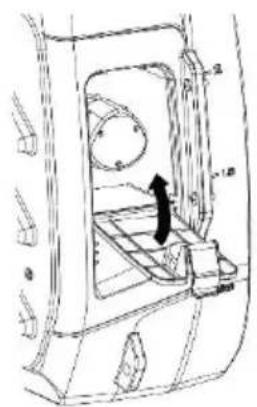
natural_image
Technical line drawing of a mechanical component with no visible text or symbolsnatural_image
Technical line drawing of a mechanical device with a rod and lever assembly (no text or symbols)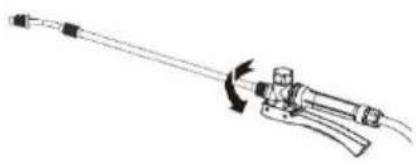
natural_image
Line drawing of a mechanical tool with an arrow indicating rotation or movement (no text or symbols)7. Emploi
natural_image
Illustration of hands operating a mechanical device with arrows indicating rotation (no text or symbols)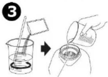
text_image
③text_image
Technical diagram illustrating cable installation steps with labeled components and directional arrowsnatural_image
Diagram of a car interior showing a button and two buttons with a pointer, labeled 'a' (no text or symbols beyond the label)natural_image
Diagram of a car interior showing a button and indicator lights (no text or symbols)natural_image
Illustration of a medical or laboratory device being adjusted, showing two sequential steps with no text or symbols.7. Funcionamiento
natural_image
Illustration of hands operating a mechanical device with arrows indicating rotation (no text or symbols)
text_image
Diagram showing a chemical experiment with a beaker and stirring rod, followed by a hand pouring liquid into a beaker.| a | tubo |
| b | almohada amortiguador |
| c | tapa compartimento de pilas |
text_image
Technical diagram illustrating cable installation steps with labeled components and directional arrowsnatural_image
Diagram of a car interior showing a button with a pointer and label 'a' (no text or symbols beyond the label)a
natural_image
Diagram of a car interior showing a button and indicator lights (no text or symbols)b
natural_image
Technical line drawing of a door panel with handle and door, showing internal components and a curved arrow indicating direction (no text or symbols)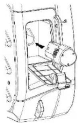
natural_image
Technical line drawing of a mechanical device with no visible text or symbols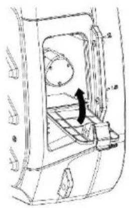
natural_image
Technical line drawing of a vehicle door frame with internal compartments and a black arrow indicating a component (no text or symbols present)natural_image
Technical line drawing of a mechanical device with a lever and handle (no text or symbols)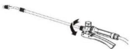
natural_image
Line drawing of a mechanical tool with a rotating arm and handle (no text or symbols)7. Anwendung
natural_image
Illustration of hands operating a mechanical device with arrows indicating rotation (no text or symbols)
text_image
③text_image
Technical diagram illustrating cable installation steps with labeled components and directional arrowsnatural_image
Diagram of a car interior showing a button and two buttons with a label 'a' pointing to the bottom (no text or symbols on the diagram itself)a
trwa ładowanie
natural_image
Diagram of a car's rear bumper with a highlighted square and directional arrows, labeled 'b' (no text or symbols on the diagram itself)b
natural_image
Technical line drawing of a vehicle door panel with handle and side-mounted buttons (no text or symbols)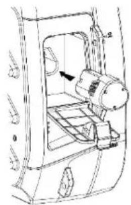
natural_image
Technical line drawing of a mechanical device with no visible text or symbols
natural_image
Technical line drawing of a mechanical component with no visible text or symbolsnatural_image
Technical line drawing of a mechanical device with a rod and lever assembly (no text or symbols)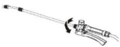
natural_image
Line drawing of a mechanical tool with a curved arrow indicating rotation (no text or symbols)7. Obsługa
natural_image
Illustration of hands operating a mechanical device with arrows indicating rotation (no text or symbols)
text_image
③text_image
Technical diagram illustrating cable installation steps with labeled components and directional arrowsnatural_image
Diagram of a car interior showing a button and two buttons with a pointer, labeled 'a' (no text or symbols beyond the label)a
natural_image
Diagram of a car's rear bumper with a highlighted square and directional arrows, labeled 'b' (no text or symbols on the diagram itself)b
natural_image
Three technical line drawings of a vehicle interior frame with internal components and directional arrows (no text or symbols)natural_image
Illustration of a medical or laboratory device being adjusted, showing two sequential steps with no text or symbols.7. Utilização
natural_image
Illustration of hands operating a mechanical device with arrows indicating rotation (no text or symbols)
text_image
③text_image
Technical diagram illustrating cable installation steps with labeled components and directional arrows| a | interruptor on/off |
| b | lança |
| c | gatilho |
Velleman® Service and Quality Warranty
Since its foundation in 1972, Velleman® acquired extensive experience in the electronics world and currently distributes its products in over 85 countries. All our products fulfil strict quality requirements and legal stipulations in the EU. In order to ensure the quality, our products regularly go through an extra quality check, both by an internal quality department and by specialized external organisations. If, all precautionary measures notwithstanding, problems should occur, please make appeal to our warranty (see guarantee conditions).
General Warranty Conditions Concerning Consumer Products (for EU):
- All consumer products are subject to a 24-month warranty on production flaws and defective material as from the original date of purchase.
- Velleman® can decide to replace an article with an equivalent article, or to refund the retail value totally or partially when the complaint is valid and a free repair or replacement of the article is impossible, or if the expenses are out of proportion.
You will be delivered a replacing article or a refund at the value of 100% of the purchase price in case of a flaw occurred in the first year after the date of purchase and delivery, or a replacing article at 50% of the purchase price or a refund at the value of 50% of the retail value in case of a flaw occurred in the second year after the date of purchase and delivery.
- Not covered by warranty:
- all direct or indirect damage caused after delivery to the article (e.g. by oxidation, shocks, falls, dust, dirt, humidity...), and by the article, as well as its contents (e.g. data loss), compensation for loss of profits;
- consumable goods, parts or accessories that are subject to an aging process during normal use, such as batteries (rechargeable, non-rechargeable, built-in or replaceable), lamps, rubber parts, drive belts... (unlimited list);
- flaws resulting from fire, water damage, lightning, accident, natural disaster, etc....:
- flaws caused deliberately, negligently or resulting from improper handling, negligent maintenance, abusive use or use contrary to the manufacturer's instructions;
- damage caused by a commercial, professional or collective use of the article (the warranty validity will be reduced to six (6) months when the article is used professionally):
- damage resulting from an inappropriate packing and shipping of the article; - all damage caused by modification, repair or alteration performed by a third party without written permission by Velleman®.
- Articles to be repaired must be delivered to your Velleman® dealer, solidly packed (preferably in the original packaging), and be completed with the original receipt of purchase and a clear flaw description.
- Hint: In order to save on cost and time, please reread the manual and check if the flaw is caused by obvious causes prior to presenting the article for repair. Note that returning a non-defective article can also involve handling costs.
- Repairs occurring after warranty expiration are subject to shipping costs. - The above conditions are without prejudice to all commercial warranties.
The above enumeration is subject to modification according to the article (see article's manual).