
FUBW50120 - Alarm system ABUS - Free user manual and instructions
Find the device manual for free FUBW50120 ABUS in PDF.

| Product type | Wireless PIR-microwave motion detector |
| Brand | ABUS |
| Model | FUBW50120 |
| Category | Wireless alarm system |
| Detection technology | Passive infrared (PIR) + microwave (AND combination) |
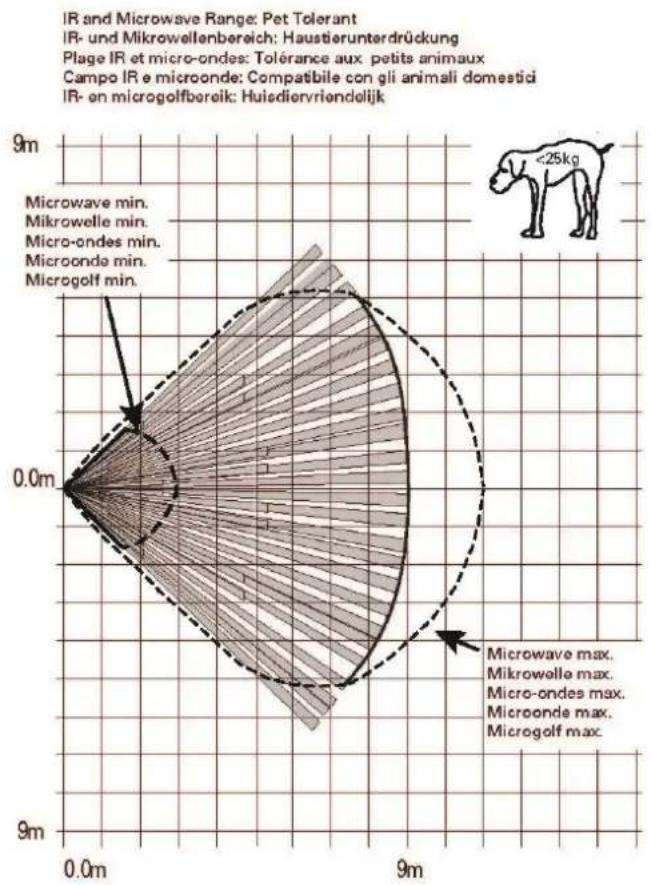
| Detection range | 12 m x 90° (standard), 9 m x 90° (pet immunity) |
| Detection angle | 90° fan-shaped |
| Pet immunity | Up to 25 kg (activated by jumper) |
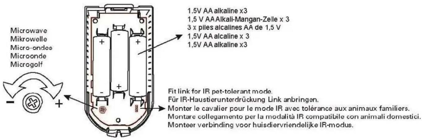
| Power supply | 3 AA LR06 1.5 V alkaline batteries |
| Battery life | Up to 48 months (normal conditions) |
| Dimensions (L x H x D) | 55 x 115 x 55 mm |
| Weight | 0.112 kg (without batteries), 0.180 kg (with batteries) |
| Housing material | PC/ABS |
| Protection rating | IP34 (indoor, mounted) |
| Operating temperature | -10 °C to +55 °C |
| Radio frequency | 868.6625 MHz |
| Radio range | Up to 1,000 m (free field) |
| Security grade | Grade 2 (EN 50131-1) |
| Tamper protection | Tamper contact (opening and removal) |
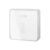
| LED display | 3 LEDs (green, yellow, red) for test and version |
| Optimal mounting height | 1.8 m to 2.3 m |
| Package contents | Detector, 3 AA batteries, housing screws, quick start guide |
| Warranty | 2 years |
| Maintenance | External cleaning, battery replacement every 2-3 years |
| Cleaning | Clean with a soft, dry cloth |
Frequently Asked Questions - FUBW50120 ABUS
User questions about FUBW50120 ABUS
0 question about this device. Answer the ones you know or ask your own.
Ask a new question about this device
Download the instructions for your Alarm system in PDF format for free! Find your manual FUBW50120 - ABUS and take your electronic device back in hand. On this page are published all the documents necessary for the use of your device. FUBW50120 by ABUS.
USER MANUAL FUBW50120 ABUS
natural_image
Simple line drawing of a cylindrical object with a curved base and a semicircular top (no text or symbols)DE
Secvest Wireless Motion Detector, PIR and Microwave
Installation instructions and user manual
FR
natural_image
Technical line drawing of a mechanical component with multiple circular holes and mounting brackets (no text or symbols)

Ruhezeit
natural_image
Simple line drawing of a cylindrical container with a checkmark symbol (no text or labels)
natural_image
Simple line drawing of a cylindrical object with a cross symbol on the right side (no text or labels)
Hinweis

Gefahr
line
| Time (m) | Value | | -------- | ----- | | 0.0 | 2.3 | | 12 | 0.0 |Haustier Tolerant
line
| Time | Value | |------|-------| | 0.0m | 2.3m | | 9m | 0.0m |natural_image
Pure technical line drawing of a mechanical component with no text or symbols
natural_image
Pure technical diagram of a screw with cross mark, no text or symbols present
natural_image
Simple line drawing of two screws with one shaded and one crossed, no text or symbols presenti Hinweis
natural_image
Simple line drawing of a cylindrical object with a curved base and a semicircular top (no text or symbols)DE
Secvest Wireless Motion Detector, PIR and Microwave
Installation instructions and user manual
FR
Intended use by the user 35
Limitation of liability 35
Terms and definitions....36
Safety information....38
Explanation of symbols 38
Packaging 38
Information on the battery 39
Scope of delivery 39
Technical data....40
Functional principle and features....43
General 43
Device description....45
Rest period....45
Compatible equipment 46
Position 46
Installation 48
Step 1: Select installation location for the motion detector....48
Step 2: Installing the motion detector ....51
Step 3: Programming the motion detector ....52
Step 4: Close the housing....53
Step 5: Test the system ....53
Step 6: Close the housing....54
Functions and displays 55
Function of the LEDs 55
Error and tamper monitoring....56
Time conditions....56
Factory settings....56
Maintenance 57
Maintenance by the user....58
Warranty 59
Customer service and support 59
Decommissioning the detector....60
Disposal 60
Declaration of conformity....60
Introduction
Information on user guide
Dear customer,
Thank you for purchasing this product. This device is a product that has been built using state-of-the-art technology.
This manual contains important installation and operation information (last updated 10/2019 with software version v1.6). Follow the directions and instructions in this user manual to ensure safe operation. Store this manual in a safe place for future reference. This manual constitutes part of the device. If you pass the device on to third parties, please remember to include this manual.

Note
S/W 1.6
This manual relates to software version 1.6 of the detector and all other previously published software versions. All new features that are only valid from a certain software version are marked accordingly, e.g. >=1.4. All other features that are valid up to a certain software version are also marked accordingly, e.g. <1.4.
This manual relates to the software version >= v3.01.14 of the Secvest alarm panel FUAA50xxx. Menu descriptions in earlier versions and other systems may differ.
Intended use
Only use the device for the purpose for which it was built and designed. Any other use is considered unintended. This product complies with current domestic and European regulations.

Note
The detector with the microwave frequency of 9.35 GHz and a maximum microwave transmission power of 20 mW can be used in the following countries:
Germany, Austria, Switzerland, Netherlands, Belgium, Denmark

Note
The detector with the microwave frequency of 9.35 GHz and a maximum microwave transmission power of 20 mW may not be used in the following countries:
UK, France, Italy, Spain, Sweden
Conformity has been certified, and all related certifications are available from the manufacturer on request.
To ensure this condition is maintained and that safe operation is guaranteed, it is your obligation as the user to observe this user guide. If you have any questions, please contact your specialist dealer. Further general information and information on product support can be found at
www.abus.com on the general page or for dealers and installers, in the Partner portal.

Note
Please observe the notes and instructions in this user manual! If you do not follow these instructions, any guarantee claim is invalidated. No liability can be accepted for consequential damage.
No part of the product may be changed or modified in any way.

Danger
Set the alarm panel to installer mode before starting any installation or maintenance work. Installer mode prevents alarms from being activated when the motion detector is opened.
Intended use by the user

Danger
After commissioning and during ongoing operation, always ensure that the detector's field of vision is neither partially nor completely obstructed.
If the field of vision is obstructed, the detector's functionality is restricted, meaning it may not be able to detect any potential intruders.
You must provide this information to all users and operators of the alarm system.
Brief employees/relatives on this information and, if necessary, provide them with further information on the functionality of the detector.
Limitation of liability
Everything possible has been done to ensure that the content of these instructions is correct. However, neither the author nor ABUS Security-Center GmbH & Co. KG can be held liable for loss or damage caused by incorrect or improper installation and operation or failure to observe the safety instructions and warnings. No liability can be accepted for consequential damage. No part of the product may be changed or modified in any way. If you do not follow these instructions, your warranty claim will be invalid.
Subject to technical modifications.
© ABUS Security-Center GmbH & Co. KG, 10/2019
Terms and definitions
| PIR | Passive infrared or pyroelectric infrared sensorAmongst other things, PIR sensors are used in motion detectors to detect the thermal radiation emitted, e.g. by living beings like humans, from up to one metre away. This can trigger various actions, such as an alarm message.The sensor reacts to small changes in temperature, e.g. when a person passes by.The sensor works best when movement is transverse to the detector. |
| IR | InfraredHeat emission in the infrared spectral rangeInfrared radiation is often equated with thermal radiation, even though both microwaves and visible light, like the entire electromagnetic spectral range, cause a rise in temperature.In physics, infrared radiation is electromagnetic radiation that lies between visible light and long-wave terahertz radiation in the spectral range. Infrared therefore usually refers to light with a wavelength between 1 mm and 780 nm. This corresponds to a frequency range of 300 GHz to 400 THz.Application:PIR detector technologyElectronicsInfrared remote control, optocouplers and most light barriers work in the near-infrared range at wavelengths of 880–950 nm as that is where silicon photodiodes and phototransistors are the most sensitive. Infrared interfaces in electronic technology also mostly work within these wavelength ranges and enable wireless communication with peripheral devices (e.g. programming components into the Terxon wireless extensions or into the WAM). |
| Pyroelectric sensor | A semiconductor sensor which is used to detect changes in temperature. PIR sensors are based on pyroelectricity, hence the name, which is a characteristic of some piezoelectric semiconductor crystals. Here, a change in temperature ΔT results in a measurable change in electric voltage. PIR sensors do not react to certain temperature levels that remain constant over time like other temperature sensors, but only to the change in temperature. |
| Microwaves | Microwaves is a trivial name for electromagnetic waves with a frequency of 1–300 GHz, which corresponds to a wavelength of approx. 30 cm to 1 mm. The frequency range of microwaves includes parts of the decimetric wave range, as well as the centimetre and millimetre wave range; at its lower end, i.e. toward the lower frequencies, the microwave range meets the infrared range; towards its higher end it meets the infrared range of the optical spectrum.ApplicationMicrowaves are used in radar technology, microwave ovens and many other technical applications including wireless communications systems (mobile communications, Bluetooth, satellite broadcasting, Wi-Fi, amateur radio) and sensor systems (e.g. radar).Detector technologyMotion detectors utilise the Doppler effect produced by signals.They work best when movement is longitudinal to the detector.Motion detectors using microwaves respond optimally when the distance to the sensor changes. |
| Doppler effect | The Doppler effect is temporal compression or elongation of a signal caused by changes in distance between the transmitter and receiver for the duration of the signal. The cause is the change in duration. This purely kinematic effect occurs for all signals which spread out at a specific speed, mostly the speed of light or sound.For periodic signals, the observed frequency increases or decreases. This affects both pitches and modulation frequencies, e.g. the familiar change in pitch of a passing police siren.In the case of Doppler radar, a movement (approaching or moving away) of an object is detected by the measured frequency change between the transmitted and reflected signal. |
Safety information
Explanation of symbols
The following symbols are used in this manual and on the device:
| Symbol | Signal word | Meaning |
 | Danger | Indicates a risk of injury or health hazards. |
 | Danger | Indicates a risk of injury or health hazards caused by electrical voltage. |
 | Important | Indicates possible damage to the device/accessories. |
 | Note | Indicates important information. |
 | The EU Directive WEEE 2012/19/EU governs the proper return, treatment and recycling of used electronic devices. This symbol means that, in the interest of environmental protection, the device must be disposed of separately from household or industrial waste at the end of its lifespan in accordance with applicable local legal guidelines. Used devices can be disposed of at official recycling centres in your country. Obey local regulations when disposing of material. Further details on returns (also for non-EU countries) can be obtained from your local authority. Separate collection and recycling conserve natural resources and ensure that all the provisions for protecting health and the environment are observed when recycling the product. |
Packaging

Danger
Keep packaging material and small parts away from children.
There is a risk of suffocation!
Remove all packaging material before using the device.
Information on the battery

Danger

Danger
The device is supplied with direct current from batteries. To guarantee a long lifespan and avoid fire and injury, please note the following:
- Do not dispose of the battery with household waste.
- The battery must not be directly exposed to heat or sunlight, and must not be stored in hot places.
• The battery must not be burned. - The battery must not come into contact with water.
- The battery must not be dismantled, pierced or otherwise damaged.
- The battery contacts must not be short-circuited.
- The battery must be kept out of reach of small children.
• The battery cannot be recharged.

Note
Battery life
The battery life can reach 48 months under the following conditions.
• 160 activations per day
- 160 activations = 1x every 3 minutes (continuous movement) for 8 hours per day
Scope of delivery
• 1x Secvest Wireless Motion Detector
- 3x AA batteries
- 1x Housing screw
- Quick guide
Technical data
| Product name | Secvest wireless motion detector, PIR microwave | |
| Product description | Passive infrared detector and microwave detector | |
| Item no | FUBW50120 | |
| Manufacturer | ABUS Security-Center GmbH & Co. KG | |
| Environmental class | II (EN 50131-1 + A1:2009 Section 7) | |
| Protection class, IP protection class | IP34 (internal spaces, in its installed state)IP = international protection or ingress protection3 = tools and wires4 = splashing water | |
| Operating temperature | -10°C to +55°C | |
| Storage temperature | -10°C to 40°C | |
| Humidity, max. | Non-condensing average relative humidity 75% | |
| Housing material | PC/ABS | |
| Dimensions (W x H x D) | 55 x 115 x 55 mm | |
| Weight | 0.122 kg (without batteries)0.180 kg (with batteries) | |
| Security level | Grade 2 (EN 50131-1 + A1:2009 Section 6) | |
| Tamper monitoring | yes | |
| Tamper protection (detection/protection) | Type B (EN 50131-3:2009 Section 8.7) | |
| Displays | Status LED for software status, IR programming and displaying detection/sending (only in the first 30 min) | |
| Optimal installation height | Between 1.8 m and 2.3 m | |
| Detection range | 12 m x 90° | 9 m x 90° with pet-proof jumper |
| Power supply type | Cable type W (EN 50131-4:2010 Section 5.6.3.2) | |
| Type of power supply | Type C with reference to EN 50131-1:2006+A1:2009+ A2:2017 Section 9 andEN 50131-6 Section 4.1 | |
| Operating voltage | 4.5 V DC | |
| Battery undervoltage threshold | 3.4 V“Flat battery” fault at < 3.4 VBatteries spent at 3.1 V | |
| Voltage monitoring | During operation the voltage provided by the batteries is monitored.If the voltage is below the lower threshold of 3.4 V, a fault report is sent to the alarm control panel and the user is informed. | |
| Power consumption | 20 μA standby current | |
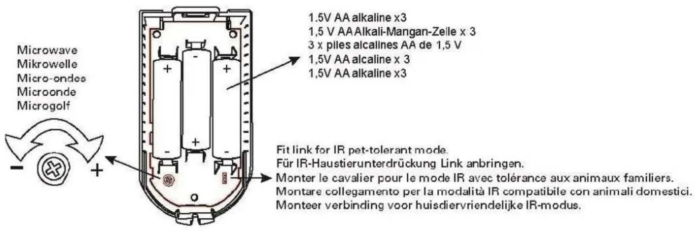
| Battery type | 3 x 1.5 V AA LR06 alkaline batteriesDuracell Procell MN1500, Duracell Industrial ID1500,Energizer E91 | |
| Battery life | over 2 years | |
| Standby time of the energy storage system | Type W (EN 50131-4:2009 Section 5.6.3.2) for battery operation only, without external power supply via power supply unit. | |
| Operating frequency | 868.6625 MHz narrow band | |
| Wireless power output | max. 10 mW | |
| Transmission and reception range | up to 1000 m range outdoors | |
| Wireless identification | Wireless components, differentiation16,777,214 ( 2^24 -2) different IDs | |
| Supervision notification | approx. every 4 minutes | |
| Microwave frequency | 9.35 GHz | |
| Microwave transmission power | Max. 20 mW | |
| Microwave frequency approved at national level | iNoteThe detector with the microwave frequency of 9.35 GHz and a maximum microwave transmission power of 20 mW can be used in the following countries:Germany, Austria, Switzerland, Netherlands, Belgium, Denmark | |
| iNoteThe detector with the microwave frequency of 9.35 GHz and a maximum microwave transmission power of 20 mW may not be used in the following countries:UK, France, Italy, Spain, Sweden | ||
| Standards for intrusion and panic button devices | in compliance according toEN 50131-2-4:2008(LED walk test disabled)EN 50131-1:2006+A1:2009+ A2:2017EN 50131-5-3:2017EN 50131-6:2017Security level 2 if installed correctly together with Secvest FUAA50xxx. | |
EU Directives
| RED | 2014/53/EU |
| EMC | 2014/30/EU |
| RoHS | 2011/65/EU |
| WEEE | 2012/19/EU |
| ErP | 2009/125/EU |
| Low voltage | 2014/35/EU |
| General safety | 2001/95/EG |
Certification authority
General This product must be installed by a qualified service engineer.
Functional principle and features
General
The FUBW50120 is a passive infrared (PIR) detector with microwave and is designed for indoor use. It is suitable for use with the Secvest wireless alarm system and wireless extension of the Terxon LX and Terxon MX.
Passive infrared (PIR)
The detector reacts to temperature changes.
A moving heat-radiating object (such as an intruder) in the monitored area changes the thermal image seen by the detector.
Microwave
The detector emits microwave radiation and receives the signals that reflect back off objects. If an object moves, this triggers the “Doppler effect”. The detector analyses this effect.
A moving object (such as an intruder) in the monitored area causes this Doppler effect.
These two detector criteria are combined using an AND gate in this detector. This combination reduces the frequency of false alarms.
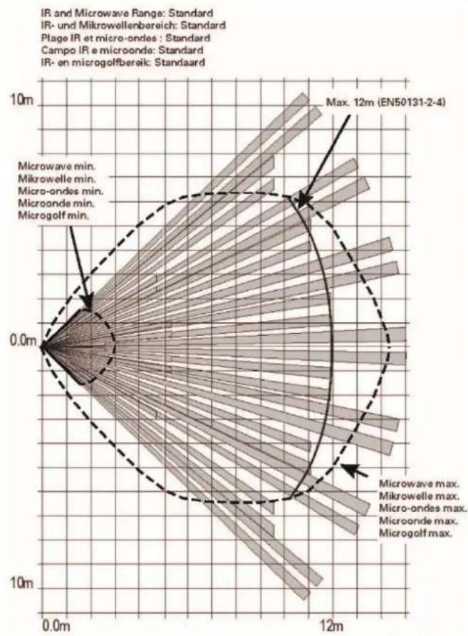
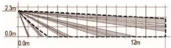
The FUBW50120 has a fan-shaped detection field with a radius of approx. 12 m and aperture angle of approx. 90°.
If "animal-proofing" is activated:
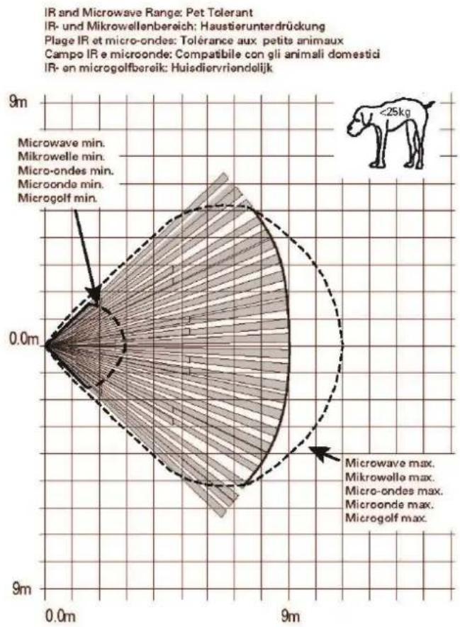
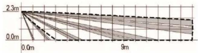
The FUBW50120 then has a fan-shaped detection field with a radius of approx. 9 m and aperture angle of approx. 90^ . The FUBW50120 now has a lower sensitivity to pets (up to approx. 25 kg). The sensitivity of the PIR element is lower.

Note
Despite being “animal-proof up to 25 kg,” animals weighing less than this amount may occasionally trigger the detector. The danger of false triggering is particularly high if the animal moves, jumps or flies in the vicinity of the detector.
However, this also has an effect on the trigger behaviour in general. The lower sensitivity to pets, for example, can be explained by lower heat emission. An adult emits more heat than a pet weighing up to 25 kg.
Thanks to an internal tamper contact, it is not possible to tamper with the housing or for it to be ripped from a wall.
| Note | A moulded part in the recess of the back plate serves as an anti-removal wall contact. This moulded part is mounted to the wall with screws.If this is not done, tamper detection for the wall is deactivated. |
| Danger | If the moulded part is not mounted to the wall, the detector will lose its certification for security level 2. |
Main features
• Uniform and technologically optimised ABUS design
- Fast reaction times
- More even coverage thanks to the spherical lens, five beam planes and dual element sensor
- Microwave transmitter and receiver
- For indoor use
- Easily accessible batteries
- If "animal-proofing" is activated, it is less sensitive to pets up to 25 kg
Device description
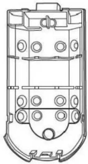
natural_image
Technical line drawing of a mechanical component with multiple circular holes and mounting brackets (no text or symbols)

Rest period
To increase the battery life and to prevent unnecessary radio emissions, a rest period function is integrated in the detector. It lasts for 3 minutes after each detection. To make it easier for you to test the detector, the rest period lasts for only 7 seconds within the first 30 minutes after installing the battery or after activating the tamper switch.
Compatible equipment
• FUAA50xxx Secvest alarm panels
• FUMO50010 Repeater Secvest
• FUMO50020 Universal module Secvest
- Wireless extensions Terxon MX and LX (IR programming)
- FU8000 and FU5000 Secvest alarm control panels
Position
The motion detector may only be installed upright
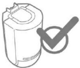
natural_image
Simple line drawing of a cylindrical container with a checkmark symbol (no text or labels)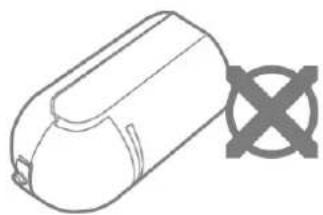
natural_image
Simple line drawing of a cylindrical object with a cross symbol on the side (no text or labels)
Note
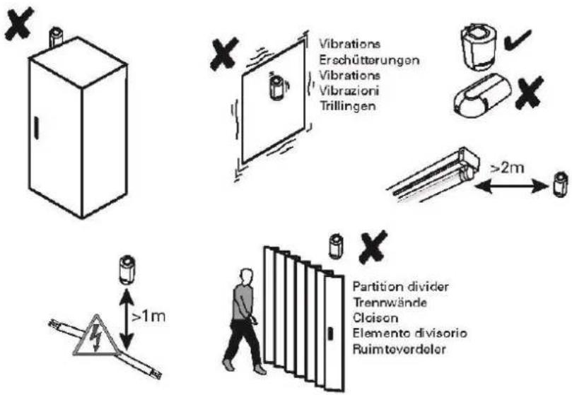
To ensure trouble-free operation, the detector must NOT be installed:
• opposite heat sources or windows
- above a radiator
- close to the ground
• closer than 30 mm to the ceiling
• behind cupboards, room partitions and partition walls
- at a distance of less than 1 m from large metal structures (such as metal doors or frames, water tanks, refrigerators), household electrical systems, power distributors or metal pipes
• inside metal housings
- close to the main power supply, or close to water or gas pipelines
- close to high-voltage devices or electronic devices such as computers, photocopiers or other wireless devices
- close to fluorescent lighting.
The following wall material can lead to a reduction in the wireless range:
- bricks
• steel-reinforced concrete, reinforced concrete
• corrugated sheet metal.
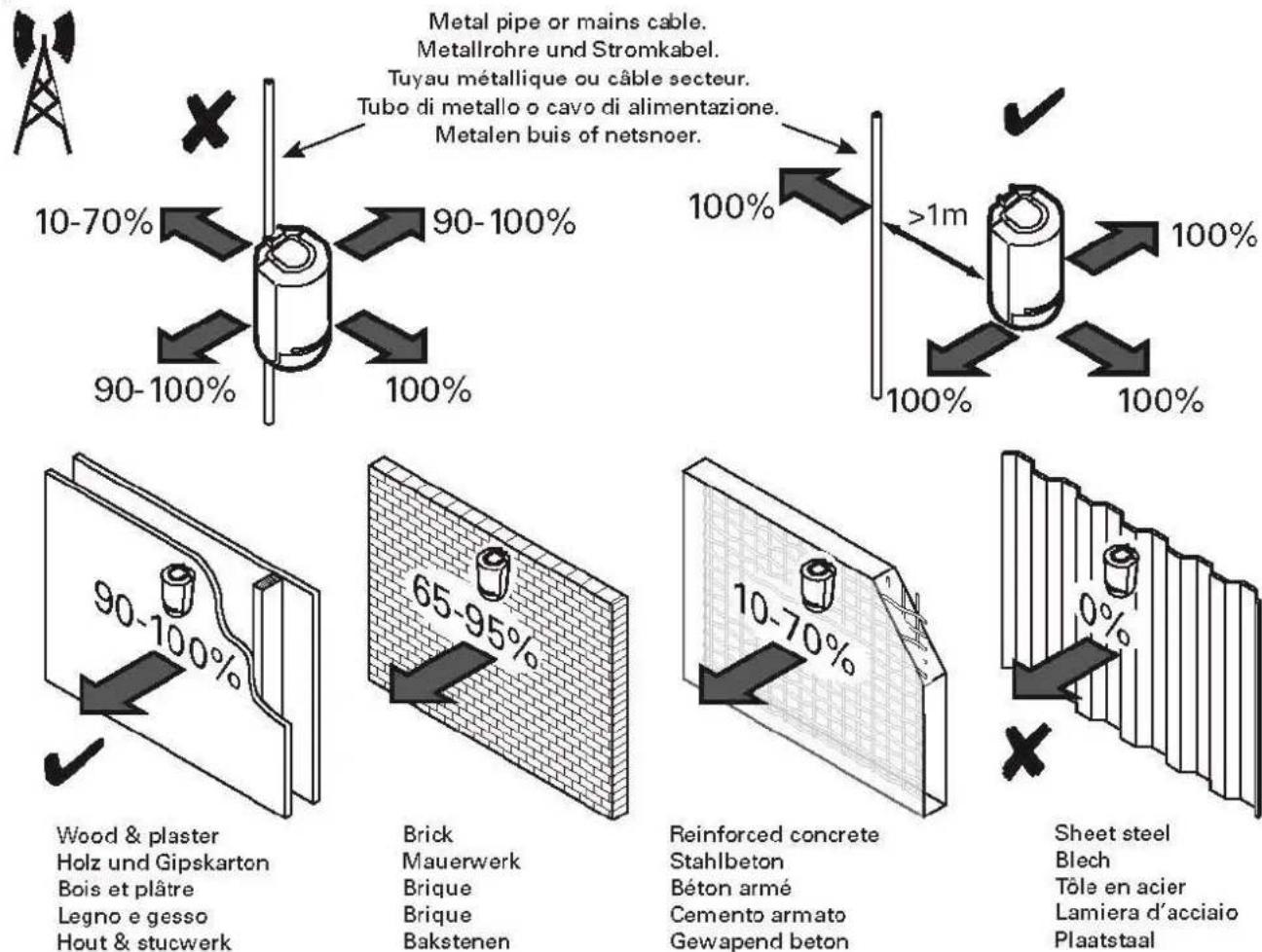
Metal pipe or mains cable.
Step 1: Select installation location for the motion detector
Select an installation location which:
- is within the wireless range of the receiver component (max. 1000 m outdoors)
• captures the desired surveillance partition.

Danger
Ensure that the detector's field of vision is neither partially nor completely obstructed.
It is imperative that this information also be provided to users and operators of the alarm system.

Note
- Before starting installation, identify a suitable installation location for the motion detector if necessary using the wireless test box.
- Incorrect or unclean installation work may lead to erroneous interpretation of signals, the consequences of which may include false alarms. The costs incurred by potential dispatches of rescue services, such as the fire service or police, must be borne by the operator of the system.
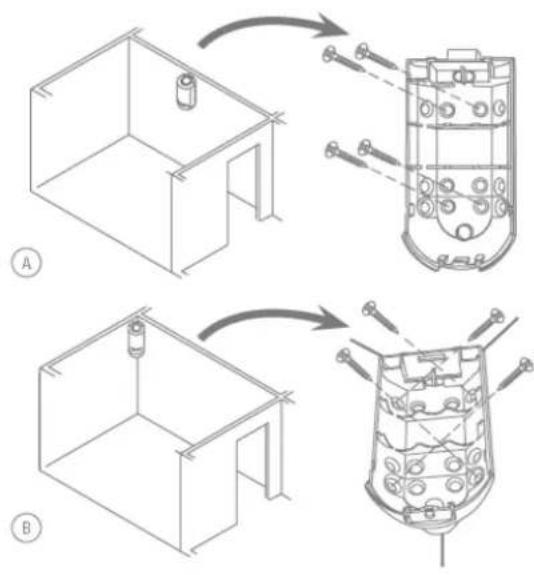
The detector can be installed either flush to the wall (see A) or in a corner (see B).

Danger

Surveillance partition:
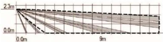
The following diagrams show the region captured by the detector.
Jumper not connected to both CON1 A contacts
Jumper connected to both CON1 A contacts
Horizontal
Standard
radar
| Category | Value | | -------- | ----- | | Microwave min. | 0.0m | | Mikrowelle min. | 0.0m | | Micro-ondes min. | 0.0m | | Microonde min. | 0.0m | | Microgolf min. | 0.0m | | Max. 12m (EN50131-2-4) | 12m |Pet-proof
radar
| Method | Range (m) | |----------------------|---------| | Microgolf min. | 0.0 | | Microondes min. | 0.0 | | Microwolle min. | 0.0 | | Microwole max. | 0.0 | | Microondes max. | 0.0 | | Microonde max. | 0.0 | | Microgolf max. | 0.0 |Vertical:
Standard
line
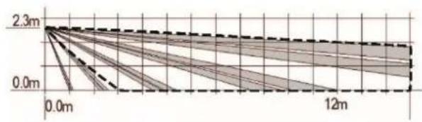
| Time | Value | |------|-------| | 0.0m | 2.3m | | 12m | 0.0m |Pet-proof
line
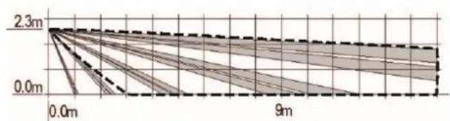
| Time (m) | Value | | -------- | ----- | | 0.0 | 2.3 | | 9 | 0.0 |For optimal detection, the detector should be mounted at a height of 180–220 cm.
Step 2: Installing the motion detector
- Open the housing by removing the screw on the bottom of the detector and taking off the front housing panel.
- Select the desired variant with the jumper connected to CON1 A
o Standard (Jumper not connected to both contacts)
o Pet-proof (Jumper connected to both contacts)

Note:
The selection must be made before inserting the batteries.
When changing the variant, remove the batteries beforehand and reinsert the batteries afterwards.
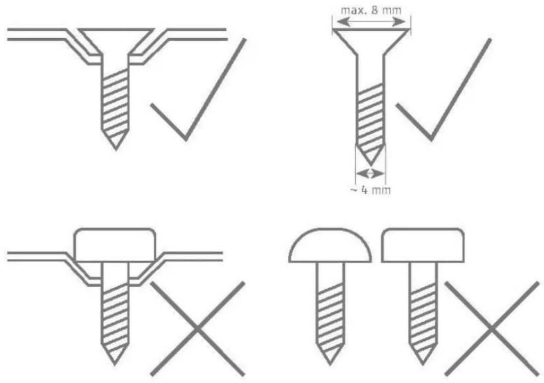
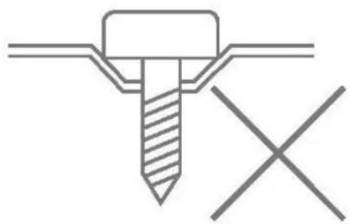
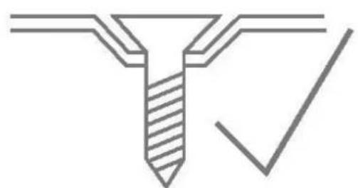
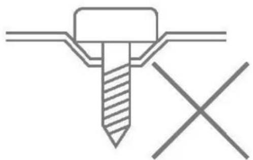
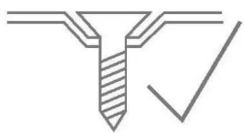
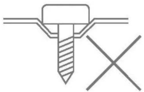
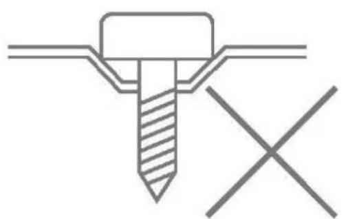
- Mount the detector as described in step 1 either on the wall or in the corner. To do this, use the holes provided on the rear housing panel.
- Only use corresponding dowels and screws for the installation.

Danger
natural_image
Pure technical diagram of a screw with a checkmark, no text or symbols present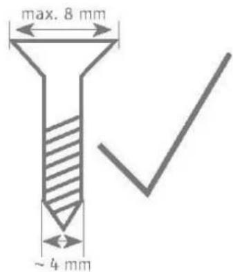
natural_image
Pure technical diagram of a screw with cross mark, no text or symbols present
natural_image
Simple line drawing of two screws with one on top and one crossed out, no text or symbols present
Thanks to an internal tamper contact, it is not possible to tamper with the housing or for it to be ripped from a wall.
A moulded part in the recess of the back plate serves as an anti-removal wall contact. This moulded part is mounted to the wall with screws.
If this is not done, tamper detection for the wall is deactivated.
Step 3: Programming the motion detector
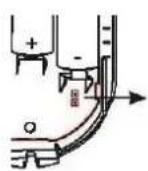
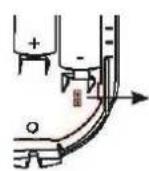
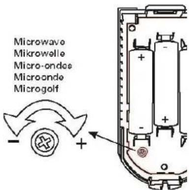
- Insert the AA batteries provided, ensuring the polarity is correct.
- Remove the insulation sheet after the batteries have been inserted.
- Set the receiver component to programming mode. Follow the instructions provided in your receiver instructions.
Wireless option
- Trigger the tamper contact of the motion detector to send a tamper message to the receiver component.

IR option

Note:
The detector's IR programming mode only lasts for a short time after the batteries have been inserted.
See Chapter "Operation of the LEDs"
- The IR programming is active if the red LED flashes 4 times.
- Hold the LED of the motion detector close to the IR receiver of the wireless extension (RFX) so that the detector can send an IR message to receiver component.
- Ensure that the motion detector has been recognised by your receiver component.
Step 4: Close the housing
- Close the cover and loosely tighten the cover fixing screws
- The tamper switch must be closed.
- The front of the housing must be in the final position for the subsequent tests.
Step 5: Test the system
- Reopen the housing by removing the screw on the bottom of the detector and taking off the front housing panel.
- The receiver component must remain in installer mode so that the control panel doesn't trigger a tamper alarm.
Setting the microwave range:
- Set the microwave range to the minimum.
- Enable tampering or insert batteries.
- Replace the cover.
- Walk test (deactivates after 30 minutes).
○ Green = IR detection.
○ Yellow = Microwave detection.
○ Red = Confirmed IR and microwave detection.
- Increase the microwave range until lit red.

Note
Do not increase the range beyond the surveillance partition. Otherwise the motion detector may react to motion in surrounding areas.
Walk test
- Set the alarm system to walk test mode (see corresponding user guide).
- Leave the area monitored by the detector and wait for the rest period after each test (see "Rest period").
- Carry out several walk tests to test the surveillance partition.
- If the detector is triggered when it is not meant to be triggered, please check the installation location of the detector again (see "Position").

A 30-minute walk test period is integrated in the detector. It begins when the batteries are inserted or when the tamper contact is opened.
The LEDs are activated during this period and the 3-minute rest period is deactivated. The detector can be triggered again during this period approx. 7 seconds after completion of the last HF transmission.
Step 6: Close the housing
- Close the cover and fully tighten the cover fixing screws.
Functions and displays
Function of the LEDs
LED layout:
| Green | Red | Yellow |
After the batteries have been inserted, the red and green LEDs should flash and display the version number. The red LED will display the main version and the green LED the minor version.
Example:
| Green | Red | Yellow |
| 1x | ||
| 6x |
Software version: v1.6
The yellow LED will then briefly flash, followed by four flashes from the red LED.
The IR programming is active if the red LED flashes 4 times.
Hold the LED of the motion detector close to the IR receiver of the wireless extension (RFX).
See also "Step 3: Programming the motion detector"
Now the LEDs should flash in sequence from left to right and back again. This lasts for 60 s and confirms the stabilisation of the detector after switching on.
For the next 30 minutes, the detector is in walk test mode. The LEDs indicate detection and transmission as follows.
| Green | Red | Yellow |
| Microwave detection | ||
| IR detection | ||
| Confirmed IR and microwave detectionWireless emission |

Note:
The 3-minute rest period is not active during the walk test period.
After the 30-minute walk test period has elapsed, the LEDs are deactivated.
• to extend battery life
- to prevent someone from identifying the surveillance partition during the day when the alarm panel is deactivated.

Note:
The 3-minute rest period is now active.
Error and tamper monitoring
The detector continually monitors error and tamper states and reports all events to the receiver component. The following is monitored:
- Tamper contact: The detector's tamper contact is continually monitored.
- Battery voltage: The detector monitors the battery voltage under load conditions and reports faults to the receiver component.
- Supervision The detector continually sends supervision messages to the alarm panel.
Time conditions
The detector was designed so that changes are detected if they last at least 400 ms (EN50131-1 Chapter 8.9.1 and EN50131-3 Chapter 8.9 and Annex B).
Breaking and entering, intrusion and tampering signals must last at least 400 ms.
The detector was designed so that changes to the fault statuses (fault signals) are detected if they last at least 10 s (EN50131-1 Chapter 8.9.1 and EN50131-3 Chapter 8.9 and Annex B).
Factory settings
The detector has no special factory settings.
However, the placement of the potentiometer for the microwave range and the CON1 A jumper for "animal-proofing" should be observed.
When not in use, unprogram the detector from the receiver component.
Before programming the detector into a new receiver component, unprogram the detector from the previous receiver component. This will prevent a tamper alarm from being accidentally triggered in the previous control unit.
Maintenance

Danger
Before opening the detector housing, make sure that the alarm panel is in installer mode. This prevents the tamper alarm from being triggered.
Test during routine maintenance that the detector works properly. Check the tamper contact. Check for signs of insects having made their way in to the device and clean as required. Replace the batteries every two to three years or if the alarm panel displays the message "Flat battery in detector". You can find the battery type to be used as a replacement under Technical data.

Note
Only use the specified battery types or batteries of an equivalent quality according to the technical data. The detector has been tested with these battery types, and works to its full capability with them.
We advise against using cheap batteries which may not be suitable for this purpose.

Note
After removing the old batteries, wait 30 seconds before inserting the new batteries.

Note
Batteries and the device itself must be disposed of in accordance with the WEEE Directive and applicable local and national regulations.

Note:
How to replace the batteries:
- Put the alarm panel in installer mode.
- Remove the screw from the underside and open the housing.
• Take out the batteries. - Wait 30 seconds, then insert the new batteries.
- Close the housing and re-tighten the screw on the underside.
- Test the system.
The detector should be checked once a year. During every inspection:
- Check the detector for visible signs of damage on the housing or the front cover.
- Check the condition of the tamper switch.
- Check the detector for visible signs of damage or wear.
- Clean your detector.
- Check the condition of the batteries.
- Check the charging status of the batteries
- Replace the batteries when recommended by the manufacturer
- Test the detector.
- Check the signal strength
• Test the communication. - EN 50131-7 “Alarm systems – intrusion and hold up alarms – part 7: application rules” must also be taken into consideration.
It is not necessary to check any calibrations or adjustments.
Maintenance by the user
- Clean the exterior of the detector.
- The user does not need to carry out any other maintenance work.
- The user can test the detector using the alarm panel's user menu (walk test).
Warranty

Note
- ABUS products are designed and manufactured with the greatest care and tested according to the applicable regulations.
- The warranty only covers defects caused by material or manufacturing errors at the time of sale. If there are demonstrable material or manufacturing errors, the component will be repaired or replaced at the warrantor's discretion.
- In such cases, the warranty ends when the original warranty period of two years expires. All further claims are expressly rejected.
- ABUS will not be held liable for defects and damage caused by external influences (e.g. transport, use of force, operating errors), inappropriate use, normal wear and tear, or failure to observe the instructions in this manual.
- In the event of a warranty claim, the original receipt with the date of purchase and a short written description of the problem must be supplied with the product.
- Should you discover a defect on your product that was already present at the time of purchase, please contact your dealer directly within the first two years.
Customer service and support
End consumer
Please consult your dealer or installer if you have any questions.
Dealer/installer
In case of questions, please contact the appropriate support hotline.
Consult our website for product information.
Decommissioning the detector
- Select:
Installer mode -> Components -> Detector -> Wireless zones -> Add/Remove detector-> 2xy zone
- Select the desired zone (on the desired detector).
- You will receive the message "Reset zone?". Press "Select" and then "Yes".
- Remove the detector's power supply.
- Remove the installation and dismount the detector.
Disposal
Dispose of the device in accordance with EU Directive 2012/19/EU – WEEE (Waste Electrical and Electronic Equipment). If you have any questions, please contact the municipal authority responsible for disposal. Information on collection points for waste equipment can be obtained from your local authority, from local waste disposal companies or your retailer, for example.
Declaration of conformity
ABUS Security-Center GmbH & Co. KG hereby declares that this type of wireless system, item number FUBW50120, complies with the RED Directive 2014/53/EU. The full EU Declaration of Conformity text can be found at: www.abus.com > Item search > FUBW50120 > Downloads
The Declaration of Conformity can also be obtained from the following address:
natural_image
Simple line drawing of a cylindrical object with a curved base and a semicircular top (no text or symbols)| DE | Secvest Funk-Bewegungsmelder, PIR und Mikrowelle Installations- und Bedienungsanleitung |
| EN | Secvest Wireless Motion Detector, PIR and Microwave Installation instructions and user manual |
| FR | Secvest Détecteur de Mouvement sans Fil, PIR-Microondes Instructions d’installation et d’utilisation |
| NL | Secvest Draadloze Bewegingsmelder, PIR-Microgolf Installatie- en gebruikershandleiding |
| DK | Secvest Trådløs Bevægelsesføler, PIR-Mikrobølge Installations- og betjeningsvejledning |
| IT | Radiorilevatore di Movimento Secvest, PIR-Microonde Istruzioni per l’installazione e per l’uso |
| CE | BOM No | Version 1.6 |
Table des matières
natural_image
Technical line drawing of a mechanical component with multiple circular holes and a curved base (no text or symbols)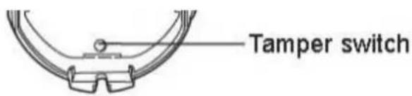
Temps de repos
natural_image
Simple line drawing of a cylindrical container with a checkmark symbol (no text or labels)
natural_image
Line drawing of a cylindrical electronic component with a cross symbol on the side (no text or labels)
Remarque

Danger
natural_image
Pure technical line drawing of a Y-shaped component with a checkmark, no text or symbols present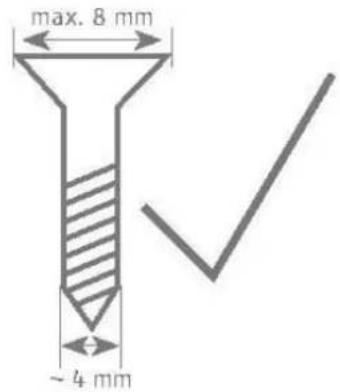
natural_image
Pure technical diagram of a screw with cross mark, no text or symbols present
natural_image
Simple line drawing of two screws with one shaded and one crossed, no text or symbols presentline
| Distance (m) | Value | | ------------ | ----- | | 0.0 | 2.3 | | 12 | 0.0 |line
| Time (m) | Value (m) | | -------- | --------- | | 0.0 | 2.3 | | 9 | 0.0 |natural_image
Pure technical line drawing of a screw with a checkmark, no text or symbols present

natural_image
Pure technical diagram of a screw with cross mark, no text or symbols present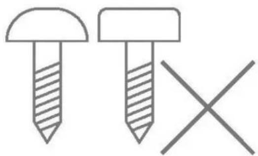
natural_image
Simple line drawing of two screws with one shaded and one crossed, no text or symbols present
Remarque
natural_image
Simple line drawing of a cylindrical object with a curved base and a flat top (no text or symbols)| DE | Secvest Funk-Bewegungsmelder, PIR und Mikrowelle Installations- und Bedienungsanleitung |
| EN | Secvest Wireless Motion Detector, PIR and Microwave Installation instructions and user manual |
| FR | Secvest Détecteur de Mouvement sans Fil, PIR-Microondes Instructions d’installation et d’utilisation |
| NL | Secvest Draadloze Bewegingsmelder, PIR-Microgolf Installatie- en gebruikershandleiding |
| DK | Secvest Trådløs Bevægelsesføler, PIR-Mikrobølge Installations- og betjeningsvejledning |
| IT | Radiorilevatore di Movimento Secvest, PIR-Microonde Istruzioni per l’installazione e per l’uso |
| CE | BOM No | Versie 1.6 |
Inhoudsopgave
Inhoudsopgave....92
Inleiding 94
natural_image
Technical line drawing of a mechanical component with multiple circular holes and mounting brackets (no text or symbols)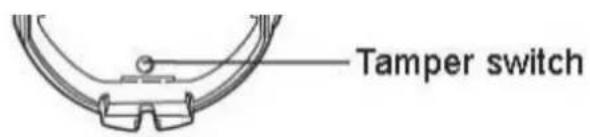

Rusttijd
natural_image
Simple line drawing of a cylindrical container with a checkmark symbol (no text or labels)
natural_image
Simple line drawing of a cylindrical device with a cross symbol on the side (no text or labels)
Aanwijzing

Gevaar

Bewakingsgebied:
line
| Time (m) | Value | | -------- | ----- | | 0.0 | 2.3 | | 12 | 0.0 |line
| Time (m) | Value | | -------- | ----- | | 0.0 | 2.3 | | 9 | 0.0 |natural_image
Pure technical line drawing of a mechanical component with no text or symbols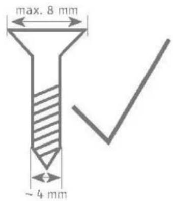

natural_image
Pure technical diagram of a screw with cross mark, no text or symbols present
natural_image
Simple line drawing of two screws with one shaded and one crossed, no text or symbols present
Aanwijzing
natural_image
Simple line drawing of a cylindrical object with a curved base and a semicircular top (no text or symbols)| DE | Secvest Funk-Bewegungsmelder, PIR und Mikrowelle Installations- und Bedienungsanleitung |
| EN | Secvest Wireless Motion Detector, PIR and Microwave Installation instructions and user manual |
| FR | Secvest Détecteur de Mouvement sans Fil, PIR-Microondes Instructions d’installation et d’utilisation |
| NL | Secvest Draadloze Bewegingsmelder, PIR-Microgolf Installatie- en gebruikershandleiding |
| DK | Secvest Trådløs Bevægelsesføler, PIR-Mikrobølge Installations- og betjeningsvejledning |
| IT | Radiorilevatore di Movimento Secvest, PIR-Microonde Istruzioni per l’installazione e per l’uso |
| CE | BOM nr. | Version 1.6 |
Indholdsfortegnelse
natural_image
Technical line drawing of a mechanical component with multiple circular holes and mounting brackets (no text or symbols)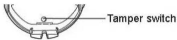

Hviletid
natural_image
Simple line drawing of a cylindrical container with a checkmark symbol (no text or labels)
natural_image
Simple line drawing of a cylindrical object with a cross symbol on the side (no text or labels)
Bemærk
natural_image
Pure technical line drawing of a screw with a checkmark, no text or symbols present

natural_image
Pure technical diagram of a screw with cross mark, no text or symbols present
natural_image
Simple line drawing of two screws with one shaded and one crossed, no text or symbols presentOvervägningsområde:
radar
| Band Type | Range (m) | | ---------------------- | --------- | | Microgolf min. | 0.0 | | Microondes min. | 0.0 | | Microonodes min. | 0.0 | | Microwelle min. | 0.0 | | Microwellike max. | 0.0 | | Microgolf max. | 10m | | Microondes max. | 10m | | Microonodes max. | 10m | | Microwelle max. | 10m | | Microwellike max. | 10m | | Microgolf max. | 10m | | Microondes max. | 10m | | Microonodes max. | 10m | | Microwelle max. | 10m | | Microwellike max. | 10m | | Microgolf max. | 10m | | Microondes max. | 10m | | Microwelle max. | 10m | | Microwellike max. | 10m | | Microgolf max. | 10m | | Microondes max. | 10m | | Microwelle max. | 10m | | Microwellike max. | 10m | | Microgalf max. | 10m | | Microondes max. | 10m | | Microwelle max. | 10m | | Microwellike max. | 10m | | Microgolf max. | 10m | | Microondes max. | 10m | | Microwelle max. | 10m | | Microwellice max. | 10m | | Microgolf max. | 10m | | Microondes max. | 10m | | Microwelle max. | 10m | | Microwellike max. | 10m | | Microgolf max. | 10m | | Microondes max. | 10m | | Microwelle min. | 10m | | Microwellike min. | 10m | | Microonodes min. | 10m | | Microwellike min. | 10m | | Microgolf min. | 10m | | Microondes min. | 10m | | Microwelle min. | 10m | | Microwellike min. | 10m | | Microgolf max. | 10m | | Microondes max. | 10m | | Microwelle max. | 10m | | Microwellike max. | 10m | | Microgolf max. | 10m | | Microondes max. | 10m | | Microwelle min | 10m | | Microwellike min | 10m | | Microonodes min | 10m | | Microwellike min | 10m | | Microgolf min | 10m | | Microondes min | 10m | | Microwelle min | 10m | | Microwellike min | 10m | | Microgolf max | 10m | | Microondes max | 10m | | Microwelle max | 10m | | Microwellike max | 10m | | Microgolf max. | 10m | | Microondes max | 10m | | Microwelle min | 10m | | Microwellike min | 10m | | Microonodes min | 10m | | Microwellike min | 10m | | Microgolf min | 10m | | Microondes min | 10m | | Microwellike min | 10m | | Microgolf max | 10m | | Microondes max | 10m | | Microwelle max | 10m | | Microwellike max | 10m | | Microgolf max. | 10m | | Microondes max | 12m | | Microwellike max | 12m | | Microonodes min | 12m | | Microwellike min | 12m | | Microgolf min | 12m | | Microondes min | 12m | | Microwellike min | 12m | | Microgolf max | 12m | | Microondes max | 12m | | Microwellike max | 12m | | Microwellike max | 12m (EN50131-2-4) Max (EN50131-2-4) Max (EN50131-2-4) Max (EN50131-2-4) Max (EN50131-2-4) Max (EN50131-2-4) Max (EN50131-2-4) Max (EN50131-2-4) Max (EN50131-4) Max (EN50131-4) Max (EN50131-4) Max (EN50134) Max (EN50134) Max (EN50134) Max (EN50134) Max (EN50134) Max (EN50134) Max (EN50134) Max (EN50134) Max (EN50134) Max (EN50134) Max (EN50134) Max (EN50136) Max (EN50136) Max (EN50136) Max (EN50136) Max (EN50136) Max (EN50136) Max (EN50136) Max (EN50136) Max (EN50136) Max (EN50136) Max (EN50136) Max (EN50138) Max (EN50138) Max (EN50138) Max (EN50138) Max (EN50138) Max (EN50138) Max (EN50138) Max (EN50138) Max (EN50138) Max (EN5027) Max (EN5027) Max (EN5027) Max (EN5027) Max (EN5027) Max (EN5027) Max (EN5027) Max (EN5027) Max (EN5027) Max (EN5027) Max (EN5027) Max (EN5027) Max (EN5027) Max (ANM) Max (ENM) Max (ENM) Max (ENM) Max (ENM) Max (ENM) Max (ENM) Max (ENM) Max (ENM) Max (ENM) Max (ENM) Max (ENM) Max (ENM) Max (ENM) Max (ENM) Max (ENM) Max (ENM) Max (ENM) Max (ENM) Max (ENM) Max (ANM) Max (ENM) Max (ENM) Max (ENM) Max (ENM) Max (ANM) Max (ANM) Max (ANM) Max (ANM) Max (ANM) Max (ANM) Max (ANM) Max (ANM) Max (ANM) Max (ANM) Max (ANM) Max (ANM) Max (ANM) Max (ANM) Max (ANM) Max (ANM) Max (ANM) Max (ANM) Max (ANM) Max (ANM) Max (AMN) Max (ANM) Max (ENN/NN/NN/NN/NN/NN/NN/NN/NN/NN/NN/NN/NN/NN/NN/NN/NN/NN/NN/NN/NN/NN/NN/NN/NN/NN/NN/NN/NN/NN/NN/NN/NN/NN/NN/NN/NN/NN/NN/NN/NN/NN/NN/NN/NN/NN/NN/NN/NN/NN/NN/Ma/NA/NA/NA/NA/NA/NA/NA/NA/NA/NA/NA/NA/NA/NA/NA/NA/NA/NA/NA/NA/NA/NA/NA/NA/NA/NA/NA/NA/NA/NA/NA/NA/NA/NA/NA/NA/NA/NA/NA/NA/NA/NA/NA/NA/NA/NA/NA/NA/NA/NA/MA/NA/NA/NA/NA/NA/NA/NA/NA/NA/NA/NA/NA/NA/NA/NA/NA/NA/NA/NA/NA/NA/NA/NA/NA/NA/NA/NA/NA/NA/NA/NA/NA/NA/NA/NA/NA/NA/NA/NA/NA/NA/NA/NA/NA/NA/NA/NA/NA/NA/NEA/NEA(NEA)(NEA)(NEA)(NEA)(NEA)(NEA)(NEA)(NEA)(NEA)(NEA)(NEA)(NEA)(NEA)(NEA)(NEA)(NEA)(NEA)(NEA)(NEA)(NEA)(NEA)(NEA)(NEA)(NEA)(NEA)(NEA)(NEA)(NEA)(NEA)(NEA)(NEA)(NEA)(NEA)(NEA)(MEA)(NEA)(NEA)(NEA)(NEA)(NEA)(NEA)(NEA)(NEA)(NEA)(NEA)(NEA)(NEA)(NEA)(NEA)(NEA)(NEA)(NEA)(NEA)(NEA)(NEA)(NEA)(NEA)(NEA)(NEA)(NEA)(NEA)(NEA)(NEA)(NEA)(NEA)(NEA)(NEA)(NEB(AE)(NEB(AE)(NEB(AE)(NEB(AE)(NEB(AE)(NEB(AE)(NEB(AE)(NEB(AE)(NEB(AE)(NEB(AE)(NEB(AE)(NEB(AE)(NEB(AE)(NEB(AE)(NEB(AE)(NEB(AE)(NEB(AE)(NEB(AE)(NEB(AE)(NEB(AE)(NEB(AF))|Husdyrtolerant
radar
| Category | Value | | -------- | ----- | | Microwave min. | 0.0m | | Mikrowelle min. | 0.0m | | Micro-ondes min. | 0.0m | | Microonde min. | 0.0m | | Microgolf min. | 0.0m | | Microwave max. | 0.0m | | Mikrowelle max. | 0.0m | | Micro-ondes max. | 0.0m | | Microonde max. | 0.0m | | Microgolf max. | 0.0m |Vertikal:
Standard
line
| Time | Value | |------|-------| | 0.0m | 2.3m | | 12m | 0.0m |Husdyrtolerant
line
| Time (m) | Value | | -------- | ----- | | 0.0 | 2.3 | | 9 | 0.0 |natural_image
Pure technical line drawing of a mechanical component with no text or symbols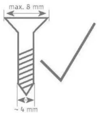
natural_image
Pure technical diagram of a screw with cross mark, no text or symbols present
natural_image
Simple line drawing of two screws with different fill patterns and a cross symbol (no text or labels)Bemærk
Softwareversion: v1.6
natural_image
Simple line drawing of a cylindrical object with a curved base and a flat top (no text or symbols)DE
Secvest Wireless Motion Detector, PIR and Microwave
Installation instructions and user manual
FR
natural_image
Technical line drawing of a mechanical component with multiple circular holes and mounting brackets (no text or symbols)
Tempo di riposo
natural_image
Simple line drawing of a cylindrical container with a checkmark symbol (no text or labels)
natural_image
Simple line drawing of a cylindrical device with a cross symbol on the side (no text or labels)
Nota

Pericolo

natural_image
Pure technical line drawing of a screw with a checkmark, no text or symbols present

natural_image
Technical diagram of a screw with a hatched head and cross mark, no text or symbols present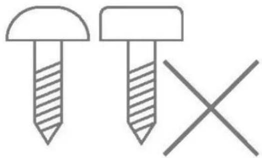
natural_image
Simple line drawing of two screws with one shaded and one crossed, no text or symbols present


- Ruhezeit
- i Hinweis
- Safety information....38
- Scope of delivery 39
- Technical data....40
- Functional principle and features....43
- Installation 48
- Functions and displays 55
- Maintenance 57
- Warranty 59
- Customer service and support 59
- Decommissioning the detector....60
- Disposal 60
- Declaration of conformity....60
- Introduction
- Information on user guide
- Dear customer,
- S/W 1.6
- Intended use
- Intended use by the user
- Limitation of liability
- Safety information
- Explanation of symbols
- Packaging
- Information on the battery
- Battery life
- Scope of delivery
- Functional principle and features
- General
- Main features
- Device description
- Rest period
- Compatible equipment
- Position
- Step 1: Select installation location for the motion detector
- Surveillance partition:
- Horizontal
- Vertical:
- Step 2: Installing the motion detector
- Step 3: Programming the motion detector
- Wireless option
- IR option
- Note:
- Step 4: Close the housing
- Step 5: Test the system
- Walk test
- Step 6: Close the housing
- Functions and displays
- Function of the LEDs
- Error and tamper monitoring
- Time conditions
- Factory settings
- Maintenance
- Danger
- Note
- Maintenance by the user
- Warranty
- Customer service and support
- End consumer
- Dealer/installer
- Decommissioning the detector
- - Select:
- Disposal
- Declaration of conformity
- Table des matières
- Temps de repos
- Remarque
- Inhoudsopgave
- Inhoudsopgave....92
- Inleiding 94
- Rusttijd
- Bewakingsgebied:
- Aanwijzing
- Indholdsfortegnelse
- Hviletid
- Overvägningsområde:
- Vertikal:
- Bemærk
- Softwareversion: v1.6
- Tempo di riposo
Brand : ABUS
Model : FUBW50120
Category : Alarm system