FXWP152 - Pump Fuxtec - Free user manual and instructions
Find the device manual for free FXWP152 Fuxtec in PDF.
| Product type | Engine-powered water pump |
| Brand | Fuxtec |
| Model | FXWP152 |
| Engine | 2-stroke, air-cooled |
| Displacement | 52.0 cm³ |
| Max. power | 1.4 kW (1.9 hp) |
| Water flow rate | 15 m³/h |
| Delivery head | 30 to 35 m |
| Suction head | 8 m |
| Max. pressure | 0.35 MPa |
| Suction pipe diameter | 1.5 inch (38 mm) |
| Delivery pipe diameter | 1.5 inch (38 mm) |
| Fuel tank capacity | 0.9 L |
| Fuel consumption | 1.0 kg/h |
| Dry weight | 9.6 kg |
| Sound pressure level (LPA) | 100.10 dB(A) |
| Guaranteed sound power level (LWA) | 113 dB(A) |
| Fuel type | Unleaded petrol + 2T oil mixture (ratio 40:1) |
| Max. engine speed | 5500 min⁻¹ |
| Idle speed | 3000 min⁻¹ |
| Warranty | 24 months |
| Usage | Domestic and garden (clean water, neutral fluids ≤40°C) |
| Maintenance | Regular air filter cleaning, spark plug check, fuel drain for storage |
| Spare parts | Available from the manufacturer (original parts recommended) |
Frequently Asked Questions - FXWP152 Fuxtec
User questions about FXWP152 Fuxtec
0 question about this device. Answer the ones you know or ask your own.
Ask a new question about this device
Download the instructions for your Pump in PDF format for free! Find your manual FXWP152 - Fuxtec and take your electronic device back in hand. On this page are published all the documents necessary for the use of your device. FXWP152 by Fuxtec.
USER MANUAL FXWP152 Fuxtec
natural_image
Golden-tinted illustration of a portable pump or pump device with control panel and valve (no text or symbols visible)natural_image
Exterior view of a black and silver industrial pump with orange internal components (no text or symbols visible)CE
text_image
Technical diagram of a pump assembly with numbered parts and exploded view, labeled with numbers 1–17.natural_image
Four metallic mechanical components with various mounting holes and washers, shown from different angles (no text or symbols visible)natural_image
Close-up of a mechanical assembly with red arrow indicating a component (no visible text or symbols)
natural_image
Close-up of a mechanical component with orange components and a red arrow indicating a specific part (no visible text or symbols)
natural_image
Close-up of an orange automotive component with a black plastic cover and red arrow indicating a cable or connector (no text or symbols visible)natural_image
Close-up of a black and orange electric shock absorber with a hand adjusting its top panel, showing a red arrow indicating the tool (no text or symbols visible)
natural_image
Close-up of a hand adjusting a black and orange industrial machine component with a red arrow indicating the adjustment (no visible text or symbols)natural_image
Close-up of a hand adjusting a black Fuxtec brand air purifier with orange handle (no visible text or symbols)natural_image
Close-up of a black industrial machine with orange and white components, no visible text or symbolsWartung Zündkerze
text_image
0.6~0.7mmnatural_image
Exterior view of a black and orange industrial pump unit (no visible text or symbols)CE
Your new device has been developed and designed to meet FUXTEC's high standards, such as easy operation and user safety. Properly treated, this device will serve you well for years to come.

WARNING: To reduce the risk of injury, the user must read and understand this manual before operating the device.
FUXTEC GMBH
KAPPSTRAße 69, 71083 HERRENBERG, GERMANY
TABLE OF CONTENTS
- TECHNICAL DATA 27
- SYMBOLS AND SAFETY INSTRUCTIONS ON THE DEVICE.... 28
- INTENDED USE AND GENERAL SAFETY INSTRUCTIONS .... 30
- COMPONENT OVERVIEW.... 32
- ASSEMBLY OF THE DEVICE.... 33
- PRE-PUMPING THE ENGINE.... 36
- COLD START OF THE ENGINE 36
- WARM START OF THE ENGINE.... 37
- STOPPING THE DEVICE 38
- MAINTENANCE PLAN.... 39
- STORAGE OF THE DEVICE.... 41
- TROUBLESHOOTING.... 42
- CUSTOMER SERVICE.... 43
- WARRANTY 43
- DISPOSAL NOTE...... 43
- EC DECLARATION OF CONFORMITY 44
We are continually striving to improve our products. Therefore technical data and illustrations can change!
17. Technical data
| Typ | FX-WP143 | FX-WP152 |
| Engine | Air-cooled; 2-stroke | Air-cooled; 2-stroke |
| Cubic capacity | 42,7cm^3 | 52,0cm^3 |
| Max. output power (kW)(in accordance with ISO 8893) | 1.25KW/6500RPM | 1.4KW/7500RPM |
| Flow rate ( m^3 ) | 8CBM/H | 15CBM/H |
| Suction pipe connection (inch) | 1.0" | 1.5" |
| Pressure pipe connection (inch) | 1.0" | 1.5" |
| Max. delivery height (m) | 25-30M | 30-35M |
| Max. suction height (m) | 8M | 8M |
| Max. Pressure (Psi) | 0.3MPa | 0.35MPa |
| Maximum speed of the engine | 5500 min^-1 | 5500 min^-1 |
| Idle speed of the device | 3.000 min^-1 | 3.000 min^-1 |
| LPA at the operator station | 98.16 dB(A) (K=3dB) | 100.10 dB(A) (K=3dB) |
| Measured LWA according to ISO 10884 | 110.67 dB(A) (K=3dB) | 112.70 dB(A) (K=3dB) |
| Guaranted LWA | 113 dB(A) | 113 dB(A) |
| Dry weight (without fuel, cutting set, carrying strap) | 8.5 | 9.6 |
| Fuel tank capacity (L) | 0.9 | 0.9 |
| Fuel consumption (kg/h) (in accordance with ISO 8893) | 0.8 | 1.0 |
18. Symbols and safety instructions on the device


WARNUNG! IMPROPER USE CAN LEAD TO SERIOUS INJURY
READ AND UNDERSTAND THIS USER MANUAL BEFORE USE.
ATTENTION: DANGER OF POISONING, DO NOT INHALE FUMES
ATTENTION: HOT PARTS; DO NOT TOUCH
ATTENTION: NO OPEN FIRE
ATTENTION: CHECK FILLING LEVEL OF OIL/PETROL MIXTURE
THE GUARANTEED NOISE LEVEL CORRESPONDS TO THE LEGAL NOISE GUIDELINES
NO SMOKING AND OPEN FLAMES ON THE DEVICE

WARNING: DANGER OF HOT COMPONENTS

WARNUNG! ÄNDERN SIE NIE DIE MASCHINE. IMPROPER USE OF THE DEVICE CAN CAUSE SERIOUS OR FATAL PERSONAL INJURY.
Do not let others use this device, unless these persons have been fully instructed, have read and understood the device manual, and have been trained in the device's operation.

The operating noise of the tool may damage your hearing. Wear a sound-proofing (Oropax or ear muffs) to protect it. Long-term and regular users are recommended to check your hearing regularly. Be especially vigilant and careful when wearing hearing protection as it limits your ability to hear warnings (cries, alarms, etc.).

WARNING: Some noise exposure from this device cannot be avoided. Do not work in noisy environments during approved and designated times. If necessary, observe rest periods and limit the working time to the absolute minimum. For your protection and protection of persons in the vicinity, wear suitable hearing protection.
19. Intended use and general safety instructions
Water pumps are not intended for pumping drinking water, and an improper use can lead to injuries and material damage.
Accidents can be avoided if you follow the instructions here and on the pump. The most common sources of danger and how you can protect yourself from them are described below.
Intended use
The water pump is approved for use only in accordance
- with the descriptions given in this manual for pumping water
- and neutral liquids at room temperature
Any other use is not intended. In case of improper use for the intended purpose, any warranty will expire. The manufacturer cannot be held responsible for damages. The user is liable for all damages to third parties and their property. Unauthorized modifications to the device exclude any liability of the manufacturer for resulting damages.
Please note that our devices are not designed for commercial, trade, or industrial use. Our warranty expires if the device is used in commercial, trade, industrial operations, or similar activities.
Improper use
The use of the pump is strictly prohibited for the following substances:
- Paints and varnishes of all kinds
- all kinds of solvents or diluents
- all types of fuels or lubricants
- Propane or other liquefied gas types
- flammable liquids of all kinds
- Food for humans and animals
- Granules or substances with solid particles
- Chemicals
- Liquids with temperatures above 40°C
- all fluids that are not explicitly mentioned in this manual
- Liquids with anti-parasites, herbicides, and pesticides.
The gasoline water pump is not suitable as a safety device for fire fighting systems. The pump must not be used to fill containers that may explode under excess pressure. The FX-WP143 / FX-WP152 gasoline water pump is intended for private use in the house and garden.
Correct safety instructions must be observed. DO NOT EXPOSE YOURSELF OR OTHERS
TO DANGER. Follow these general safety instructions:
- Check the entire device for loose parts (nuts, bolts, screws, etc.). Maintain or replace them, if necessary, before using the device. Do not use accessories other than those recommended by the manufacturer. Otherwise, severe injuries to the user or bystanders and damage to the device may result
- Do not smoke when mixing the fuel or filling the tank
- Do not mix fuel in an enclosed space or near open fires. Ensure adequate ventilation / aeration
- Mix and store the fuel mixture in a marked container approved for such use according to local regulations
- Never remove the fuel tank cap while the device is running
- Do not operate the device in closed rooms or buildings. Exhaust gases contain dangerous carbon monoxide
- Do not use the device if it is damaged. Never remove safety devices from the device. Otherwise, the operator or the spectators may be seriously injured, and the device may be damaged
- Never leave the device unattended
- Children must not have access to the device. Spectators should stand at least 15 meters away from the working area.
- Do not use the device if you are tired, sick, or under the influence of medication, drugs, or alcohol
- Caution! Local regulations may limit the use of the device
- Secure the device properly during transport to prevent fuel loss, damage to the device, and injury. Always mount the transport protection of the cutting blade before transporting or stowing the device
- Check the device before each use for loose fasteners, fuel leaks, damaged parts, etc. Replace damaged parts before use
- Do not store the device in an enclosed area where fuel vapors can reach an open fire from water heaters, stoves, etc. Store the device in a well-ventilated area only.
- IMPORTANT: When filling fuel, make sure that the device is off and cooled down. Never refuel when the device is running or hot. If gasoline is spilled, wipe it up before starting the device
20. Component overview
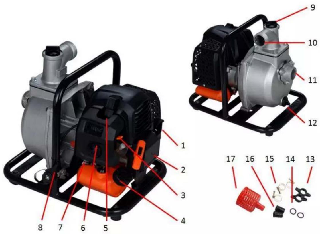
text_image
Technical diagram of a pump assembly with numbered parts and exploded view, labeled with numbers 1–17.- Exhaust
- Pullstarter
- Choke
- Tank
- Spark plug
- Air filter cover
- Primer Pump
- Throttle lever
-
Water filler neck
-
Pressure line
- Suction line
- Water drain plug
- Connection screwing
- Seals
- Hose clamps
- Hose connection
- Suction Strainer
21. Assembly of the device
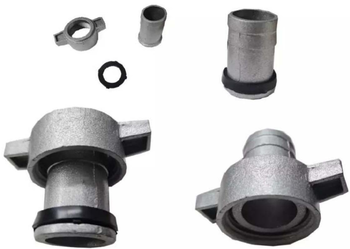
Installation of the suction line
Use a standard hose and the hose connection with hose clamp (15;16), as supplied for the pump. The suction line must be reinforced with a stiff wall or wire mesh. Do not use a hose that is smaller than the suction mouth (11) of the pump. The suction line should only be as long as necessary. The pumping performance is best when the pump is as close to
the water level as possible, and the hoses are short.
Use a hose clamp to fix the hose connection to the suction line to avoid leakage air and suction power loss. Make sure that the seal (14) of the hose connection is in good condition.
Install the filter screen (17; supplied) at the other end of the suction line and fasten it with a hose clamp. The filter screen ensures that the pump is not clogged or damaged by foreign matter. Attach the hose connection to the suction mouth (11) of the pump.
Please ensure that the seal is correctly seated, otherwise the pump will draw air and cannot provide full performance.
See the following series of pictures:
natural_image
Four views of a metallic mechanical component with various features including a flange, bolt, washer, and housing (no text or symbols visible)Installation of the pressure line
Use a standard hose and hose connector with a hose clamp, as supplied for the pump. It is best to use a short hose with a large diameter, reducing fluid friction and improving pumping performance. A long or thin hose increases fluid friction and reduces pumping capacity.
Tighten the hose clamp firmly to prevent the outlet hose from slipping under pressure.
Please ensure that the seal is correctly seated as described above, otherwise water will leak out of the free space of the wing screw.
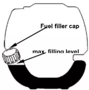
Checking the filling level of the gasoline/oil mixture
Open the fuel cap and check the fuel level. Fill up with gasoline if the fuel level is low.
WARNING
Gasoline is highly flammable and explosive. You could be burned or seriously injured when handling gasoline. Switch off the engine and keep heat sources, sparks, and open flames away. Only handle fuel outdoors. Wipe up spilled fuel immediately. Top up fuel in a well-ventilated area before starting the engine. If the engine is hot, let it cool down.
Fill up with fuel carefully so that no gasoline overflows. Do not overfill the fuel tank. Fill the tank to about 25mm below the rim to leave enough space for the gas to expand.
Depending on the
operating conditions, it may be necessary to reduce the fuel level. After refueling, close the fuel filler cap firmly. Never refuel inside a building where petrol fumes can come into contact with naked flames or sparks. Keep gasoline away from the ignition flames of devices, grills, electrical appliances, power tools, etc. Spilled fuel is not only a fire risk but also environmental pollution. Wipe up spilled fuel immediately.
NOTE
Gasoline can damage paint and plastics. Take care not to spill gasoline when filling the fuel tank. The warranty does not cover damage caused by fuel spillage.
FUEL AND 2-STROKE OIL
Use unleaded gasoline with 2-stroke engine oil in a 40:1 ratio. During the first few operations, a mixing rate of 25:1 can be selected to optimally lubricate all device parts.
WARNING: Never use pure gasoline in your device. This will cause permanent engine damage and voids the manufacturer's warranty for this product. Never use a fuel mixture that has been stored for more than 90 days.
WARNING: It must be a first-class oil for 2-stroke air-cooled devices.
FUEL MIXTURE
Mix fuel with 2-stroke oil in a particular container. Please note
the mixture table on the following page for the correct ratio of fuel to oil. Shake the tank to ensure complete mixing.
| Gasoline | Two-stroke engine oil (40:1) | Gasoline | Two-stroke engine oil (40:1) |
| 1 liter | 0.025 liter | 5 liter | 0.125 liter |
| 2 liter | 0.050 liter | 10 liter | 0.250 liter |
WARNING: Lack of lubrication excludes the liability of the device manufacturer.
Gasoline and oil must be mixed in a 40:1 ratio.
Recommended fuel
It is recommended to use unleaded gasoline with an octane number of 90 # or higher to reduce carbon deposition in the combustion chamber. Do not use old or dirty gasoline.
Keep the fuel tank dust-free and avoid water getting into the tank. Sometimes overload will cause misfiring, which is normal.
If the backfires are heard under the average load, we recommend changing the gasoline. If the misfire is still present afterward, please contact an authorized workshop.

WARNING
text_image
Fuel filler cap max. filling level● Gasoline is highly flammable and can cause an explosion in case of sparks
- Refuel only in well-ventilated rooms and let the engine cool down before filling. Smoking and open fire, as well as any sparks, must be avoided during refueling
- Do not overfill the tank (see figure max. filling level)
● After refueling, check that the fuel filler cap is properly closed
- Avoid any spillage of gasoline
- Keep the device away from children
Gasoline with an ethanol content
The engine can be operated with E10 gasoline. However, do not use gasoline with a higher ethanol content than 10%.
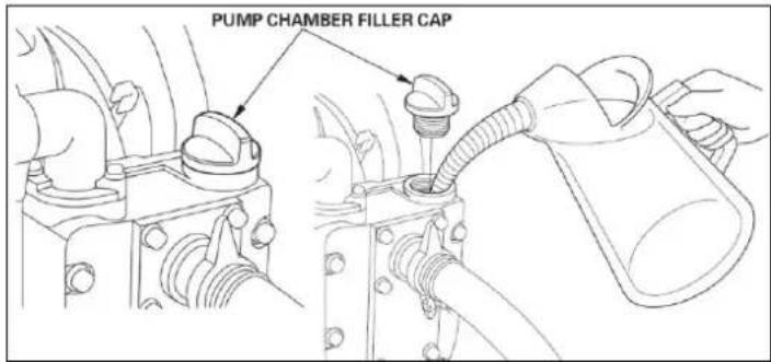
22. Pre-pumping the Engine
Before starting the engine, remove the filler cap from the pump chamber and fill it with water. Reset the filling cap and pull tight.
text_image
PUMP CHAMBER FILLER CAPNOTE
Dry operation of the pump will cause damage to the pump seals. If the pump runs dry, switch off the motor immediately and let the pump cool down before pre-pumping.
23. Cold start of the Engine
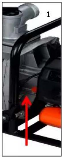
- Place the device on a firm and flat surface. Press the Start/Stop switch.
natural_image
Close-up of a mechanical device with red arrow indicating a component (no visible text or symbols)
natural_image
Close-up of a mechanical component with orange plastic parts and a red arrow indicating a specific part (no visible text or symbols)
natural_image
Close-up of an orange automotive component with a black plastic cover and wiring, no visible text or symbols- Move the choke lever upwards to "COLD START."
- Press the carburetor pump about 8-10 times (until gasoline flows in the line)
- Pull out the starter rope with a short-stroke until resistance is felt
(about 100mm). A continuous, especially fast train will provide a vital spark and start the engine

natural_image
Close-up of a black and orange electric shock absorber with a hand adjusting its internal components (no text or symbols visible)
natural_image
Close-up of a hand adjusting a black industrial machine component with orange clamps (no visible text or symbols)- Then set the choke lever to the "WARM START" position
- Let the engine warm-up for about 10 minutes at idle
NOTE: If the device does not start after repeated attempts, refer to troubleshooting chapters.
NOTE: Always pull the starter cord straight out. Pulling the starter at an angle will cause the rope to rub against the eyelet. Pulling the starter at an angle can cause the starter cord to fray or break. Always hold the starter handle firmly when the rope pulls back. Never let the rope be thrown back from the pulled-out position. This could damage the starter device.
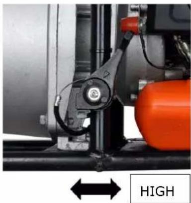
Adjusting the pump capacity
After the engine has been started, the pumping capacity can be adjusted via the throttle lever. Move the throttle lever towards the device to increase the flow rate, move it forward towards the pipe to decrease it (only for model FX-WP152)
natural_image
Close-up of a mechanical assembly with orange components and a directional arrow labeled 'HIGH' (no readable text or symbols beyond label)LOW
24. Warm start of the engine
- Place the device on a firm and flat surface.
- Move the engine stop switch down
- Slide the choke to the "WARM START" position
- Pull out the starter rope with a short-stroke until resistance is felt (about 100mm). A continuous, especially fast train will provide a vital spark and start the engine
If the device does not start, please proceed again according to "Cold start of the device
25. Stopping the device
Slide the throttle stick to the LOW position. Let the device return to idle. Push the engine stop switch to the OFF position upwards until the device stops. If it does not control, pull out the spark plug connector in an emergency. Never leave the device unattended while it is running.
26. Maintenance plan
Regular checks and adjustments must be made to ensure that the gasoline engine maintains its performance. Periodic maintenance also provides a long service life. See the following table for the regular maintenance cycle.
| MaintenancecycleComponent | Everyuse | Everymonthor 10h | Every 3monthsor 25h | Every 6monthsor 50h | Every12monthsor 100h | Every 2years or300h | |
| Air Filter | Check | ■ | |||||
| Clean up | ■a | ||||||
| Spark plug | Check &adjust | ■ | |||||
| Exchange | ■ | ||||||
| Spark plugconnector(optional) | Clean up | ■ | |||||
| Cooling fins | Exam | ■ | |||||
| Connectingelements suchas screws andnuts | Check(tighten ifnecessary) | ■ | |||||
| Coupling | Exam | ■b | |||||
| Idle speed | Check andadjust | ■b | |||||
| Valveclearance | Check andadjust | ■b | |||||
| Combustion chamber | Clean up | 300 h after that | |||||
| Fuel | Check | ■ | |||||
| Fuel tank | Check | ■ | |||||
| Fuel line | Check | Every x years (replace if necessary) | |||||
WARNING

a. Increase maintenance intervals if working in dusty environments.
b. All maintenance work - except that listed in the operating manual must be carried out by qualified maintenance personnel

natural_image
Close-up of a hand adjusting an orange FUXTEC-branded device with black casing and orange handle (no visible text or symbols)Cleaning the air filter
CAUTION: Never run the engine without the air filter.
A dirty air filter puts pressure on engine performance, increases fuel consumption, and makes starting more difficult. If you notice a loss of engine power:
1 Remove the screw on the filter cover and remove the filter.
2. Clean the filter with soap and water. Never use gasoline or benzene!
3 Let the filter dry in the air.
4 Put the filter back in place and fasten the filter cover with the screw.

natural_image
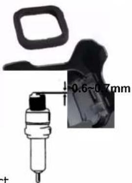
Close-up of a black industrial machine with orange and white components, no visible text or symbolsSpark plug maintenance
To ensure the engine's normal operation, the ignition distance of 0.6 -0.7mm must be maintained and free of carbon deposits. Always carry out the following steps with the engine switched off:
text_image
0.6~0.7mm- Carefully remove the spark plug connector. Do not pull on the cable but directly on the plug
- Use the spark plug wrench supplied to unscrew the spark plug
- Visually check the spark plug for damage and electrode burn-off, Remove the carbon deposits
- Check the gap with a feeler gauge and bend the electrode to the correct distance of 0.6 to 0.7mm

- Check the spark plug washer and tighten the spark plug with a torque of 12-15 Nm
- Mount the ignition cap back on the spark plug
WARNING
The spark plug must be screwed tight, or the engine will run hot and be damaged.
27. Storage of the device

WARNING: Failure to follow these steps may result in carburetor fouling. This makes later starting difficult and causes permanent damage
- Perform all general maintenance recommended in the maintenance section of your user manual.
- Clean the exterior of the device, drive axle, protective shield, and nylon cutting head.
- Drain fuel from the fuel tank.
- After fuel is drained, start the device.
- Let the device idle until the device stops by itself. This will clean the carburetor of fuel.
- Let the device cool down (about 5 minutes).
- Use a spark plug wrench, remove the spark plug.
- Pour 1 teaspoon of clean 2-stroke oil into the combustion chamber. Pull the starter rope
slowly several times to coat the internal components. Replace the spark plug. - Store the device in a cool, dry place away from any ignition source such as an oil burner, water heater, etc.
TRANSPORT PROTECTION
Make sure that the device is well-secured during transport to avoid fuel loss, damage, or injury. Install transport protection for metal sheets during transport and storage
28. Troubleshooting
- Difficulties during commissioning
| Situation | Cause | Solution | |
| No ignition spark | Spark plug | Carbon deposit between the diodes of the spark plug | Clean the spark plug. Adjust the gap 0.6~0.7mm, replace the spark plug |
| Other | Ignition coil defective flywheel magnet too weak | Replace the ignition coil or flywheel | |
| Weak ignition spark | Compression | Too much gasoline in the combustion chamber, bad fuel or water in the tank | Remove the spark plug and allow to dry, replace fuel. |
| The carburetor does not pump oil anymore. | Oil line blocked | Cleaning the carburetor and cleaning the pipes | |
| Regular oil supply but weak compression | Piston rings worn, spark plug not screwed down, cylinder head not tight wrong valve clearance or ignition timing. | Replace screw tight replace or adjust | |
| Regular oil supply and good ignition spark | Poor contact between ignition cap and spark plug | Replace or check | |
- Difficulties during operation
| Situation | Cause | Solution |
| The engine does not reach the speed | Choke is in "COLD START" position, the exhaust system is blocked, no air supply, moving elements worn, ignition spark weak too large valve clearance, cylinder head sooty | Open choke, replace exhaust system Check or replace ignition coil, adjust flywheel, spark plug |
| Operating materials are leaking | Lines to carburetor blocked Spark plug spacing incorrect | Replace lines and carburetor Adjust gap dimension |
| Engine Noises | Wrong choke position, Camshaft damaged | Check/replace camshaft |
| Carburetor leaking | Failure of the check valve on the tank cap | Replace the fuel filler cap |
| The carburetor gasket is worn out | Replace carburetor or gasket |

If no troubleshooting solves the problem, contact your dealer or the manufacturer directly. Only use original parts approved by the manufacturer. Otherwise, there is a risk of danger.
29. Customer Service
Have your purchased device repaired only by qualified personnel and only with original spare parts.
This ensures that the safety of the device is maintained.
If you do not have authorized service centers' addresses, please contact the sales office where you purchased the device.
30. Warranty
The warranty period is 24 months from the date of purchase. Keep your proof of purchase in a safe place. Excluded from the warranty are wearing parts and damage caused by improper use, use of force, technical modifications, wrong accessories or non-original spare parts, and repair attempts by non-qualified personnel. Authorized dealers may only carry out warranty repairs.
31. Disposal note
Please contact your local community for the disposal of the device. Please dispose of all functional materials such as gasoline and oil in advance.
32. EC Declaration of Conformity
Herewith we,
FUXTEC GMBH
KAPPSTRAße 69, 71083 HERRENBERG, GERMANY
declare that the device described below, due to its design and construction and in the version marketed by us, complies with the relevant essential health and safety requirements of the EC directives.
Designation of the device:
Gasoline water pump
Device type:
FX-WP143, FX-WP152
Trademark:
FUXTEC
Power consumption/capacity
42.7cm ^3 , 52.0cm ^3
Measured sound power level
L_WA=110.7dB/112.7dB
Guaranteed sound power level
LWA=113dB
Relevant EC straightening thread:
EC device straightening thread 2006/42/EG
EC Directive on Electromagnetic Compatibility (EMC)
2004/108/EC
EC-directive thread Noise emission (2000/14/EWG & 2005/88/EC)
Manufacturer signature/date:
C. Jille
L. Zirkler, January 5th 2023
The name and address of the person authorized to compile the technical documentation established within the community
Leonhard Zirkler
FUXTEC GMBH - KAPPSTRAße 69, 71083 HERRENBERG, GERMANY
MODE D'EMPLOI ORIGINAL
natural_image
Exterior view of a black and orange industrial pump mounted on a metal frame (no text or symbols visible)CE
text_image
Technical diagram of a pump assembly with numbered parts and exploded view, labeled with numbers 1–17.natural_image
Four views of a metallic mechanical component with various features including a flange, bolt, washer, and housing (no text or symbols visible)natural_image
Close-up of a mechanical device with red arrow indicating a component (no visible text or symbols)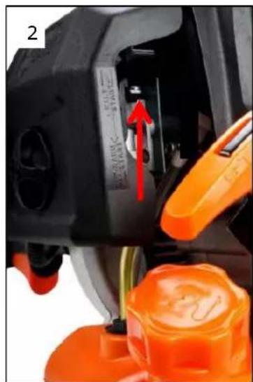
natural_image
Close-up of a mechanical component with orange plastic parts and a red arrow indicating a specific part (no visible text or symbols)
natural_image
Close-up of an orange automotive component with a black plastic housing and wiring, no visible text or symbolsnatural_image
Close-up of a black and orange electric shock absorber with a hand adjusting its internal components (no text or symbols visible)
natural_image
Close-up of a hand adjusting a black industrial machine component with orange tool handles (no visible text or symbols)natural_image
Close-up of industrial machinery components including a red valve and orange cylindrical tank, no visible text or symbolsnatural_image
Close-up of a hand adjusting a black SUXTEC® electronic device with orange handle (no visible text or symbols)natural_image
Close-up of a black and orange industrial machine component with no visible text or symbolstext_image
0.6~0.7mm
AVERTISSEMENT
Directive machines CE 2006/42/EG
natural_image
Exterior view of a black and silver industrial pump with orange internal components (no visible text or symbols)CE
text_image
Technical diagram of a pump assembly with numbered parts and exploded view, labeled with numbers 1–17.natural_image
Four metallic mechanical components with various mounting holes and washers, shown from different angles (no text or symbols visible)natural_image
Close-up of a mechanical device with red arrow indicating a component (no visible text or symbols)
natural_image
Close-up of a mechanical component with orange tool and red arrow indicating a step, no visible text or symbols
natural_image
Close-up of an orange automotive component with a black plastic cover and red arrow indicating a cable or connector (no text or symbols visible)natural_image
Close-up of a black and orange electric shock absorber with a hand adjusting its internal air gap, no visible text or symbols.
natural_image
Close-up of a hand adjusting a black industrial machine component with orange clamps (no visible text or symbols)natural_image
Industrial machinery setup with orange tank and blue valve, labeled 'LOW' and 'HIGH' (no readable text or symbols beyond labels)natural_image
Close-up of a black FUTTEC-branded industrial device with orange handle and cable, being adjusted by hand (no visible text or symbols)natural_image
Close-up of a black industrial machine with orange and black components, no visible text or symbols
natural_image
Close-up of a black plastic electronic device with a circular button and rectangular lid (no visible text or symbols)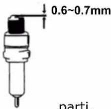
text_image
0.6~0.7mm parti.L. Zirkler, 05/01/2023
natural_image
Exterior view of a black and orange industrial pump with metallic casing and control frame (no visible text or symbols)CE
text_image
Technical diagram of a pump assembly with numbered parts and exploded view, labeled with numbers 1–17.natural_image
Four metallic mechanical components with various mounting holes and washers, shown from different angles (no text or symbols visible)MEZCLA DE COMBUSTIBLE
natural_image
Close-up of a mechanical device with red arrow indicating a component (no visible text or symbols)
natural_image
Close-up of a mechanical component with orange tool and red arrow indicating a step, no visible text or symbols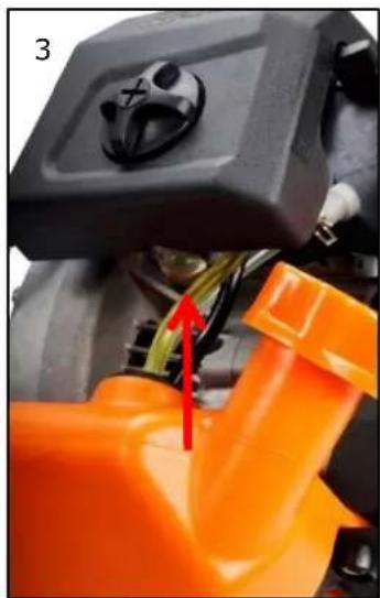
natural_image
Close-up of an orange automotive component with a black plastic cover and wiring, no visible text or symbolsnatural_image
Close-up of a black and orange electric shock absorber with a hand adjusting its top panel, showing a red arrow indicating the tool (no text or symbols visible)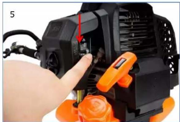
natural_image
Close-up of a hand adjusting an orange industrial machine component with a red arrow indicating the adjustment (no visible text or symbols)natural_image
Close-up of a black Fux7EC® airship component being adjusted by hand, with orange handle and cable visible (no text or symbols on the device itself)natural_image
Close-up of a black industrial machine with orange and white components, no visible text or symbols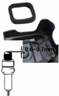
text_image
0.6~0.7mm
L. Zirkler, 05/01/2023