DriTech 4000i - Air purifier Dri Eaz - Free user manual and instructions
Find the device manual for free DriTech 4000i Dri Eaz in PDF.

User questions about DriTech 4000i Dri Eaz
0 question about this device. Answer the ones you know or ask your own.
Ask a new question about this device
Download the instructions for your Air purifier in PDF format for free! Find your manual DriTech 4000i - Dri Eaz and take your electronic device back in hand. On this page are published all the documents necessary for the use of your device. DriTech 4000i by Dri Eaz.
USER MANUAL DriTech 4000i Dri Eaz
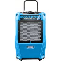
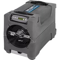
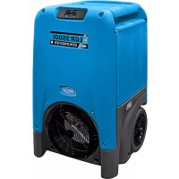
4000i Desiccant Dehumidifier Model F533 LEGEND BRANDS, INC. 15180 Josh Wilson Road, Burlington, WA 98233 Phone: 800-932-3030 Fax: 360-757-7950 www.LegendBrandsRestoration.com The Legend Brands DriTec 4000i desiccant dehumidifier reduces humidity in enclosed environments by removing water vapor from the air. The 4000i is ideal for water damage restoration, structural drying, con- struction, and is especially suited for removing moisture from structural materials and contents in cold temperatures or low to medium humidity environments where refrigerant dehumidifiers work less effi-ciently. Patents: http://www.LBpatents.com R E A D A N D S A V E T H E S E I N S T R U C T I O N S
Read and understand manual before operating.
WARNING! Do not alter or modify the unit in any way. Use only replacement parts authorized by Dri-Eaz. Modifications or use of unapproved parts could create a hazard and will void your warranty. Contact your Dri-Eaz location for assistance. WARNING! Electric shock hazard, rotating fan, hot surface hazards. Unplug unit before opening cover for cleaning or servicing. Unit must be grounded. • Inspect the power cord before use. If cord is dam-aged, do not use. Always grasp the plug (not the cord) to unplug. • Insert three-prong plug on power cord into a match-ing electrically grounded outlet. Do not use adapter. Never cut off third prong. Do not use an extension cord. • The unit must be operated on a 115V/60Hz circuit protected by a Ground Fault Circuit Interrupter (GFCI) device. • Keep motor and wiring dry. • Do not attempt to repair the unit. For Authorized Service Centers, contact Dri-Eaz. BEFORE YOU BEGIN Warranty registration Visit warranty.LegendBrandsRestoration.com to register your purchase. Registration allows us to better assist you with using, maintaining or servicing your equipment and to contact you in case we have important safety in-formation concerning your Dri-Eaz product. If you deter-mine service is required, have your equipment model, serial number and original proof of purchase available and call your distributor for assistance with obtaining a return material authorization (RMA). GROUNDING INSTRUCTIONS This unit’s plugs must be inserted into an appropriate outlet that is properly installed and grounded in accord-ance with all local codes and ordinances. WARNING! Improper connection of the equipment-grounding conductor can result in a risk of electric shock. Check with a qualified electrician or service person if you are in doubt as to whether the outlets WARNING
CORRECT PLUG REMOVAL
Grasp IEC plug and pull straight out IMPORTANT: Damage to IEC receptacle or dehumidifier resulting from improper re- moval of the power cord is not covered by warranty. The IEC power cord is a wear item and is not covered by warranty.49-109J F533 2 Legend Brands, Inc. are properly grounded. Do not modify the plugs pro-vided with the appliance – if the plugs do not fit the outlets, have proper outlets installed by a qualified electrician. This equipment is for use on circuits with a nominal rat-ing of no more than 120V. Handle the unit carefully Always operate the unit on a stable, level surface. Do not drop, throw, or place where it could fall. Rough treat-ment can damage the unit, and may create a hazardous condition or void the warranty. This unit intended for household and commercial use.
The unit is shipped with two duct rings and an adaptor kit packed inside the storage compartment. A 3 mm Allen wrench is required for installation of these components. Required: Install Reactivation Air Outlet duct ring Install the Reactivation Duct Ring, See Fig. B. Optional: Install Air Inlet duct ring Attach to inlet with the thumbscrews provided. See Fig. Optional: Install Process Air Outlet offset screws The Process Air Outlet Adaptor Kit may be installed us-ing the offset screws provided. See Fig. B.
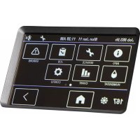
CONTROLS AND OPERATING
INSTRUCTIONS Positioning the Dehumidifier For best results, operate your dehumidifier in an en-closed area. Close all doors and windows that open to the outside to maximize water removal efficiency. Place your dehumidifier away from any obstructions that could block airflow into and out of the unit. Duct reactivation outlet outdoors through window adapter or dryer vent. Plug in electrical cords Always plug the cords firmly into the sockets in the top compartment first, then into the wall outlets. En-sure that the cords are routed properly through the cord cutout notch before closing the storage com-partment lid. NOTICE: The power cords of the DriTec must be plugged into separate GFCI-protected 120V outlets rated for at least 15A. CONTROL PANEL
Press the ON/OFF to turn the unit on. ON/OFF When the machine is turned on, the display normally reads PLEASE WAIT WARMING UP. Once the unit completes the warm-up procedure, the display shows UNIT ON XXX HRS and cycles between INLET XXX°F and INLET XX% (RH). DISPLAY MENU Cycles through the display of additional dehumidifier conditions and User Set-tings. To return to the main menu, press the ON/OFF key once. MENU SELECTION / UP KEY Change system settings. The MENU SELECTION key acts as the “UP” key for cycling through the setpoints. WATER REMOVAL Press and release to show a calculated amount of water removal in pints/day. The unit will display WATER REMOVAL XXX PINTS/24H after 5 minutes of run time. The display will automatically return to the “Unit On” display after a few seconds. Fig. A: Parts Identification Air filter Power sockets inside compartment. Stor-age for power cords, react ducting. Air inlet Reactivation Air Outlet (installation of duct re-quired)
Control panel Process Air Out- let (optional duct attachment kit provided)49-109J F533 3 Legend Brands, Inc. NOTICE: Connect to two separate 15A circuits ONLY. A bright green light on the front of the unit indicates correct connections. No light will show when using only one cord or if both power cords are plugged into the same power circuit. For best performance, use with two circuits and en- sure green light is illuminated. If a second circuit is not available, the unit may be operated on a single power cord. Plug into Circuit 1. Note that the unit will operate at 50% of the rated performance when using a single power cord. Startup display and normal display modes When unit is first plugged in to AC power, the control panel display will briefly cycle through a series of readouts. This is part of the unit’s self-diagnosis proce- dure and no user intervention is required. Ducting Setup NOTICE! For indoor use only. Do not expose the unit to rain or snow. If electrical components become wet, allow the unit to dry thoroughly before operat- ing.
1. Reactivation Outlet Ducting
Use the duct clamp provided to attach the ducting to the duct ring. The reactivation air should always be ducted to the outside. NOTICE: Temperatures inside React Out ducting can reach 150°F (66°C). Use only heat-rated ducting as provided. Process Outlet Ducting The process out air may be ducted where more focused drying is required. Use with layflat ducting only. Maximum Ducting Length To ensure maximum performance, do not exceed these ducting lengths: Reactivation air 20 ft. | 6 m Process air 10 ft. | 3 m Inlet air 30 ft. | 9.1 m For more ducting options, see Fig. C.
NOTICE Condensation may collect in the reactivation duct during opera- tion. Do not allow water to run back into the unit. This could cause a shock hazard or damage to the unit.
1. Install 4 standoff screws as shown.
ducting (pur-chased sepa-rately) through square wire frame and fold back out-side the frame.
3. Place wire frame inside offset screws and
click into place. When not in use, frame may be left in standoffs or placed in storage bin. Square wire ducting frame49-109J F533 4 Legend Brands, Inc. USER SETTINGS Only menu items followed by a greater-than symbol (>) may be adjusted. In the menu items with reading data (INLET OUTLET, REACT & HEATER1 CURRENT), If no keys are selected for 5 minutes the display will return to normal display mode. In all the other menu items, the display with return to the normal display mode after 20 seconds. Items without the symbol (>) are for information only and cannot be changed or reset. MAIN MENU: Press DISPLAY MENU to proceed to the next menu item. ↓
SUBMENUS: Press MENU SELECTION to change the setting. →
JOB HOURS XX.X Press to reset to 0.
HEATER1 CURRENT 00 A For information only.
Press to cycle through 5 – 60% at 5% increments.
Press to cycle through 0 – 30% at 5% increments.
LANGUE FRANCAIS > Press to change lan- guage options.
LIFE HOURS 00000 HRS For information only.
The following section available only on wireless-equipped units. SENSOR ID 000000000 >
NOTICE: Handle the unit carefully. Rough treatment can damage this equipment and may create a hazardous con- dition or void warranty.
- Do not expose the control panel to moisture, snow or rain.
- Store and transport securely to avoid any damaging impact to internal parts.
- Secure during transport to prevent sliding and possi- ble injury to vehicle occupants. MAINTENANCE WARNING! ELECTRIC SHOCK HAZARD. Unplug unit before cleaning or servicing.
WARNING: Risk of dust and contaminants exposure.
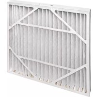
Use of respirator mask and gloves is recommended. If unit has been exposed to potentially dangerous con- taminants, clean thoroughly and disinfect before re- use. As Needed (Exterior items) Inspect filter. Replace if accumulation of dust and debris is visible. NOTICE: Replace used filters only with a new Dri-Eaz filter part no. F590 (24-pack). Other filter types do not provide adequate filtration or airflow. Each filter is in- dividually wrapped to protect filtration effectiveness. Remove the wrapper before installing the filter into the dehumidifier. To maintain appearance, wipe interior and exterior sur- faces with a damp cloth. Inspect reactivation air outlet ducting for cracks, splits or breaks. Replace as needed with suitable heat-resistant ducting. As Needed (Interior items) See Fig. D. NOTICE: Electric shock hazard. Unplug unit before re- moving side panels. NOTICE: The unit is fitted with sensitive electronic sen- sors. Protect the sensors and their lead wires from dam- age and do not expose them to water or cleaning solution. The following tools and supplies are needed to complete the maintenance procedures described in this manual:
- 3 mm Allen wrench and/or bit and cordless drill
- Vacuum cleaner with soft brush tool and/or a high pressure air nozzle Remove side panel. Remove the screws from the react out / air inlet panel. IMPORTANT: The inlet temp/RH sensor cable is attached to the interior of the panel and must be detached before setting the panel aside. To remove the cable, first unclip the plug and then slide the cable down and out of the cable tie. Once the cable is free of the panel, set the panel aside. Fig. D: Interior views Blower Storage compart- ment. React out/air in panel. Remove this panel only for routine inte- rior inspection and cleaning. IMPORTANT! Temp/RH Sensor cable is attached to inside of panel! Unclip and slide out of cable tie before setting panel aside. Detach sensor cable be- fore setting side panel aside. Be sure to rein- stall cable when replac- ing panel. Desiccant rotor React air outlet Belt tensioner (see detail be- low) Belt tensioner. Lift arm upward to release belt.49-109J F533 7 Legend Brands, Inc. Inspect and clean blower Check that the impeller rotates freely. Vacuum or wipe clean all surfaces. Inspect and clean desiccant rotor Ensure that rotor is clear of dust and debris. Vacuum or use pressurized air to remove dust from rotor. Inspect rotor belt. Check cracks or excessive wear. Contact your local distributor for replacement instructions. Vacuum interior to remove dust and debris. Wipe interior surfaces with clean, dry cloth. Do not apply water or cleaning solutions of any kind. Take care not to damage electronic sensors and wires. Reattach side panel. Reattach sensor cable inside panel. Thread the cable up through the zip tie and then plug in the cable. Now install screws, finger tight only, starting at the top and working down. Once all screws are properly started, then use a hand tool to tighten the screws snugly. Do not overtighten. Do not use a power tool to tighten screws.
The Control Panel will display the following messages when the Pump Purge Button is pressed. C O N T R O L P A N E L M E S S A G E E X P L A N A T I O N PLEASE WAIT CALCULATING Unit is calculating water removal. PERFORMANCE
Displays calculated water removal in units indicated per day. SYSTEM MESSAGES The Control Panel will display the following messages based on system performance and environmental conditions. User action, if any is required, is indicated in the third column. C O N T R O L P A N E L M E S S A G E E X P L A N A T I O N U S E R A C T I O N INITIALIZING Unit is powering up. None FIRMWARE VERSION XXX Indicates control board firmware version number. None F533-XX Model number. None OFF/ON Unit has finished powering up and is operating. None PLEASE WAIT WARMING UP Fan will not operate until unit reaches proper operating temperature, approximately 10 seconds.. None
First line: indicates total operating hours. Second line: Toggles between inlet temperature and in- let RH every 2 seconds. None HUMIDISTAT
First line: indicates unit is in humidistat mode Second line: Toggles between inlet temperature and in- let RH every 2 seconds. None PLEASE WAIT COOLING Fan will operate until unit cools down. Approx 30 sec- onds. None XXXXX POWER FAILURE> Indicates power has been interrupted during operation. Press the > key to reset CLEAN FILTER > XXXXX Prompt to clean or change filter. Change or clean filter. Press the > key to reset CLEAN ROTOR > XXXXX Prompt to clean rotor. Clean rotor. Press the > key to reset49-109J F533 8 Legend Brands, Inc. ERROR MESSAGES If the control system detects an error, it will produce an error (“ER”) message. If this occurs, first unplug the unit and then plug it back in. This will usually reset the electronics, and the unit will begin operating normally. If the error message reap- pears, refer to the explanations and solutions shown below. If these solutions do not fix the problem, contact your local authorized service center. NOTE: The message “POWER FAILURE” is not a system error. When this message is displayed, it indicates that power to unit was interrupted and then restored. To clear the message, press the MENU SELECTION key. C O N T R O L P A N E L M E S S A G E E X P L A N A T I O N A N D S O L U T I O N
CENTER Indicates a serious internal problem. The electronic control panel may require replace- ment. Contact service. Air Inlet temperature set point for cycling air conditioner to control temperature. Check AC power for low voltage.
CENTER Control panel error. The electronic control panel may require replacement. If error per- sists, contact service. ER3 CHECK ROTOR MOTOR React Temp minus Inlet Temp difference too high indicates rotor stopping – belt or drive motor issue. Check belt tension, belt failure, rotor cleats, and motor operation. ER4 CHECK AIRFLOW Heater amps too low indicates fan issue and/or inlet airflow restriction. Clear any ob- structions from inlet, clean inlet filter and/or check fan operation. ER5 REACT SENSOR CONNECT
ER5 PROCESS SENSOR CONNECT Temp sensor is open, missing, or shorted. Check that temp sensors are installed cor- rectly on control panel. If error persists, contact service. ER6 SENSOR
Inlet Temp/RH sensor is open, missing, or shorted. Check that inlet temp/RH sensor is installed correctly on control panel and inlet shroud. If error persists, contact service. ER7 CONTACT SERVICE CENTER Current sensor failure. If error persists, contact service. ER8 INVALID MODEL SETTING Incorrect or unsupported DIP switch settings. Contact Dri-Eaz service department for correct DIP switch settings.
ALL BUTTONS Key is stuck or has been held down too long. Contact service, ER10 WIRELESS
Wireless board has failed, Board is missing, shorted or has fallen off the control panel. Reinstall wireless board to clear error. Contact service.49-109J F533 9 Legend Brands, Inc. TROUBLESHOOTING F A U L T C A U S E S O L U T I O N Separate circuit in- dicator light does not illuminate Unit not plugged into two sepa- rate circuits. Incorrect wiring in the building. Plug unit into two separate circuits rated for at least 15 amps each. Locate a second 15 amp circuit in the structure. Circuit breaker trips after a few minutes of operation. Reactivation outlet not ducted. Ducting is kinked or blocked. Excessively long ducting. The Reactivation Out must always be ducted out of the area being ducted. Straighten all ducting as much as possible; remove any blockages. React ducting length should not exceed 20 ft. (6 m). Unit does not oper- ate Unit not switched on. No power to machine. Switch unit on. Check power cord connections at wall outlet and in top compartment of unit. Check supply circuit breakers. Unit operating, but room not dry Not enough time to dry. Poor air movement in room. Excessive moist air infiltration. Allow more time for drying. Increase evaporation with air movers. Seal off area to reduce infiltration. Unit removes too little water Room air is dry. Inlet air temperature is too warm. Inlet air temperature is too damp. Filter is clogged. Confirm humidity level with hygrometer. Decrease temperature of intake air. Decrease humidity of intake air. Check filter. Clean or replace as necessary. If the problem you are experiencing is not listed here, call your local distributor or contact our Service Department toll-free at 800-932-3030 for further assistance.
Amps (at 80°F/60%RH) Circuit 1: 10.7 Circuit 2: 10.8 Process air 395 CFM Reactivation air 65 CFM Water removal (at 80°F/60%RH) 118 pints/day | 55.8 L per/day Weight 95 lbs. | 43.1 kg Dimensions (H × W × D)
33.13 × 21.14 × 20.25 in.
(With handle upright = 42. 250 in.)
84.15 × 53.7 × 51.4 cm
(With handle upright = 107.3 cm.) Air filter F590 (24 pk) Safety ETL listed to CSA dehumidifier standards
WARNING: This product may expose you to
chemicals, including lead and phthalates, known to the State of California to cause cancer, birth defects, or other reproductive harm. For more information, go to P65Warnings.ca.gov PARTS INCLUDED
- Reactivation Out duct ring adapter
- Reactivation Out heat-resistant ducting, 20 ft. × 6 in.
- Air inlet duct ring adapter (optional, installation requi- red)
- Process air outlet layflat duct adaptor kit (optional, installation required)