LGR 6000Li - Air purifier Dri Eaz - Free user manual and instructions
Find the device manual for free LGR 6000Li Dri Eaz in PDF.
User questions about LGR 6000Li Dri Eaz
0 question about this device. Answer the ones you know or ask your own.
Ask a new question about this device
Download the instructions for your Air purifier in PDF format for free! Find your manual LGR 6000Li - Dri Eaz and take your electronic device back in hand. On this page are published all the documents necessary for the use of your device. LGR 6000Li by Dri Eaz.
USER MANUAL LGR 6000Li Dri Eaz
15180 Josh Wilson Road, Burlington, WA 98233
Phone: 800-932-3030 Fax: 360-757-7950 www.LegendBrandsRestoration.com
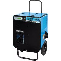
The Dri-Eaz® LGR 6000Li dehumidifier reduces humidity in enclosed environments by removing water vapor from the air. The 6000Li is rugged, durable and highly portable, making it ideal for water damage restoration, structural drying, construction, and other applications requiring temporary, high-performance dehumidification.
Patents: http://www.LBpatents.com
SAVE THESE INSTRUCTIONS

WARNING


SAFETY INSTRUCTIONS
WARNING! Do not alter or modify your dehumidifier in any way. Use only replacement parts authorized by Legend Brands, Inc., Modifications or use of unapproved parts could create a hazard and will void your warranty. Contact your authorized distributor for assistance.
WARNING! Electric shock hazard, rotating fan, hot surface hazards. Unplug unit before opening cover for cleaning or servicing. Unit must be grounded.
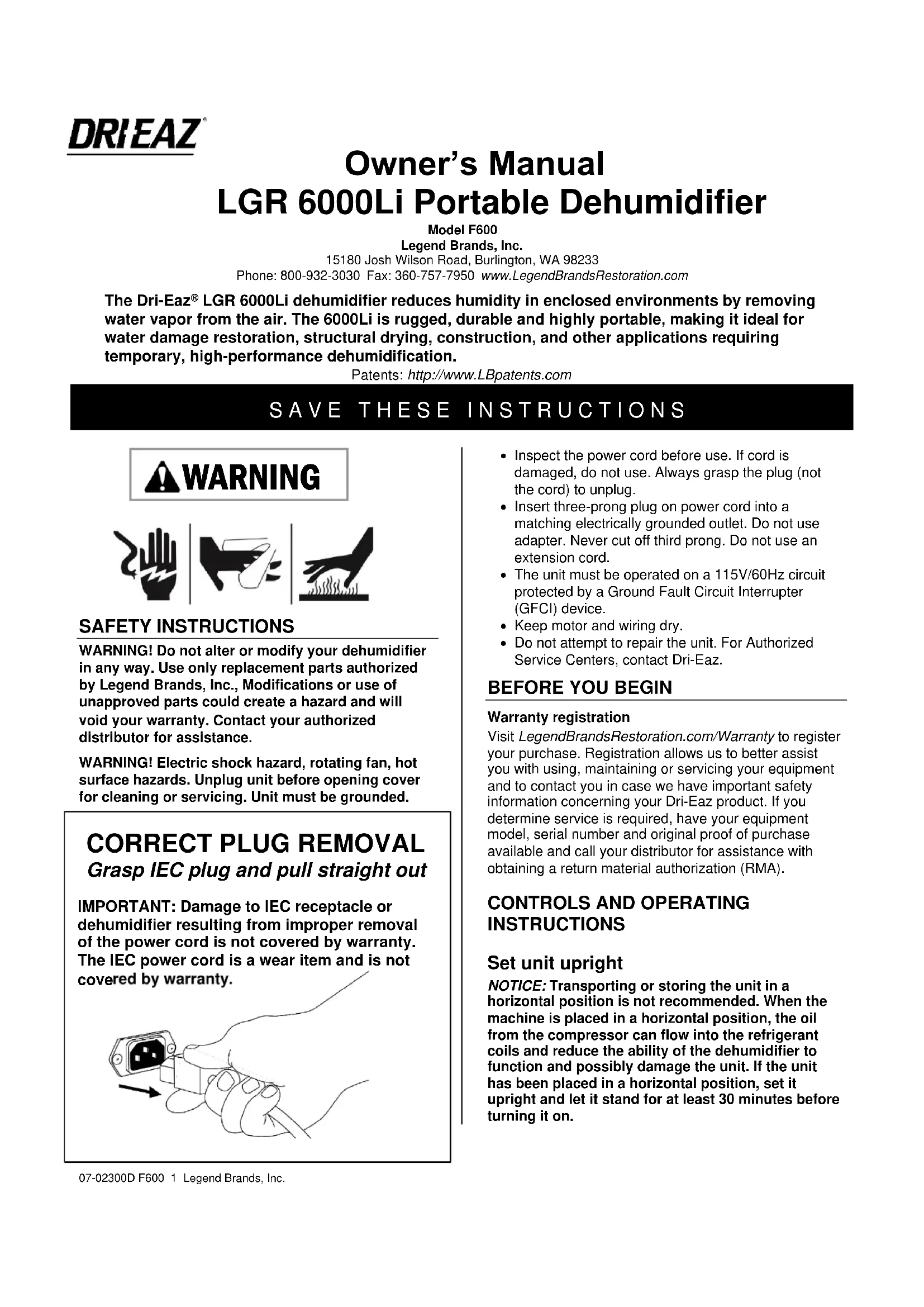
CORRECT PLUG REMOVAL
Grasp IEC plug and pull straight out
IMPORTANT: Damage to IEC receptacle or dehumidifier resulting from improper removal of the power cord is not covered by warranty. The IEC power cord is a wear item and is not covered by warranty.
natural_image
Hand holding an electrical plug with a black socket, showing a cable or wire connection (no text or symbols present)- Inspect the power cord before use. If cord is damaged, do not use. Always grasp the plug (not the cord) to unplug.
- Insert three-prong plug on power cord into a matching electrically grounded outlet. Do not use adapter. Never cut off third prong. Do not use an extension cord.
- The unit must be operated on a 115V/60Hz circuit protected by a Ground Fault Circuit Interrupter (GFCI) device.
- Keep motor and wiring dry.
- Do not attempt to repair the unit. For Authorized Service Centers, contact Dri-Eaz.
BEFORE YOU BEGIN
Warranty registration
Visit LegendBrandsRestoration.com/Warranty to register your purchase. Registration allows us to better assist you with using, maintaining or servicing your equipment and to contact you in case we have important safety information concerning your Dri-Eaz product. If you determine service is required, have your equipment model, serial number and original proof of purchase available and call your distributor for assistance with obtaining a return material authorization (RMA).
CONTROLS AND OPERATING INSTRUCTIONS
Set unit upright
NOTICE: Transporting or storing the unit in a horizontal position is not recommended. When the machine is placed in a horizontal position, the oil from the compressor can flow into the refrigerant coils and reduce the ability of the dehumidifier to function and possibly damage the unit. If the unit has been placed in a horizontal position, set it upright and let it stand for at least 30 minutes before turning it on.
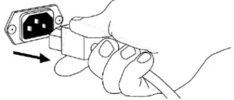
FIG A: PARTS IDENTIFICATION
FRONT
text_image
Power cord and drain hose storage. Humid air inlet. Air filter. Front panel. Remove to access the pump and coils for cleaning. See Fig. B.REAR
text_image
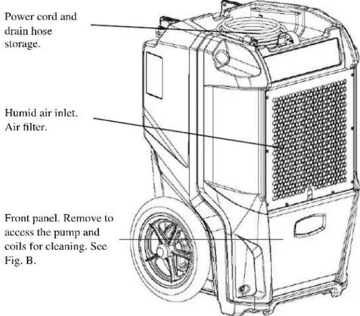
Integrated handle. Use the red lever to lock handle upright for use or down for loading or storage. Control panel. Power cord socket. Drain hose quick-connect. Model serial number label Process (dehumidified) air outlet.Positioning a Dehumidifier
For best results, operate your dehumidifier in an enclosed area. Close all doors and windows to maximize the unit's water removal efficiency. Place your dehumidifier away from obstructions, and keep it away from anything that could obstruct airflow into and out of the unit.
Extend handle
Release the handle by rotating red locking lever outward, then lift handle up into place. Rotate red lever back into locked position to secure handle in operating position.
NOTICE: Do not use the extended handle to lift the unit off the ground horizontally. Do not use the extended handle as an attachment point to strap the unit in a vehicle for transport. These uses will place undue strain on the handle attachment points in the housing.
Set up drain hose
This unit automatically pumps out water on a regular basis. This dehumidifier is equipped with a quick-connect fitting for attachment to the provided drain hose located in the tray on top of the unit. Unwrap the entire hose and place the open end in a sink, drain, bucket or outdoors – anywhere that water can drain out safely. If you use a bucket or other container for water collection, check it regularly to prevent overflows.
NOTICE: Uncoil and straighten the entire drain hose. Do not leave any part of the hose coiled on the unit and do not place the end of the hose higher than 20 ft. (6 m) above the bottom of the unit. Also check for kinks or other obstructions that might restrict the flow of water. A kink or blockage will cause the unit to turn off produce an ER9 error code. See "Error Messages," below, for more information.
Plug in electrical cord
The dehumidifier should be plugged into a GFCI-protected 115 volt outlet rated for at least 15 amps. Remove the cord from the storage tray and uncoil it. Always plug the cord firmly into the unit first, and then plug the other end into a suitable electrical outlet.
Startup display and normal display modes
When unit is first plugged into AC power, the control panel display will briefly cycle through a series of readouts. This is part of the unit's self-diagnosis procedure and no user intervention is required.
Turn the unit on
The control panel has a display and a touchpad with four keys. Press the ON/OFF to turn the unit on. The unit will now go through a compressor delay countdown (up to 60 seconds in duration) and a self-diagnostics process, then switch to normal display mode.
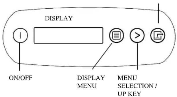
CONTROL PANEL
PURGE PUMP
text_image
DISPLAY ON/OFF DISPLAY MENU MENU SELECTION / UP KEYON/OFF
DISPLAY MENU
MENU SELECTION / UP KEY PURGE PUMP
Press and release to turn unit on or off.
Press to select next item in menu.
Menu item will show in display.
Press to toggle or select values in menu displayed.
Press and release to start purge.
Display will count down seconds remaining until purge is complete.
UNIT ON XXXX HRS INLET XXX°C / INLET 00%
The first line of the display shows the total number of hours the unit has been in operation. This value may be reset to zero to track job hours (see "Job Hours Reset" below). The second line of the display alternates between inlet temperature and inlet humidity.
User Settings Menu
A number of settings may be changed by the user. System information can also be displayed. These items are accessed by pressing DISPLAY MENU. Each press of the key will display the next parameter. When you reach the parameter you wish to adjust, press MENU SELECTION to increase the value. Press DISPLAY MENU again to accept the setting and re-start the display cycle.
Note that only menu items followed by a greater-than symbol ( > ) may be adjusted.
Error messages
If the onboard diagnostics discover a problem, the unit will display an error message. See "Error Messages," below, for an explanation of each message.
Control Panel Guide
ON/OFF. Press to turn the unit on or off. When the machine is turned on, the display normally reads PLEASE WAIT COMP. DELAY and performs a numeral countdown from a maximum of 60 seconds to 0. This delay allows time for refrigerant pressures to equalize for easier starting. Once the unit completes the compressor
delay, the display shows UNIT ON XXXX HRS and cycles between INLET XXX°C and INLET XX%. NOTE: If no compressor delay countdown is displayed, a delay is not necessary and the machine will begin operation immediately.
DISPLAY MENU. Press to cycle through the display of additional dehumidifier conditions and User Settings. To return to the main menu, press the ON/OFF key once.
MENU SELECTION. Press to change the values of the "User Defined" settings. The MENU SELECTION key acts as the UP key for adjusting the setpoint for Humidistat mode operation. See User Settings Menu (next page) for details.
PURGE. Press to empty water from the condensate pump reservoir. The display will read PUMP PURGING with a numeral countdown.
NOTE: During normal operation, the pump purges automatically.
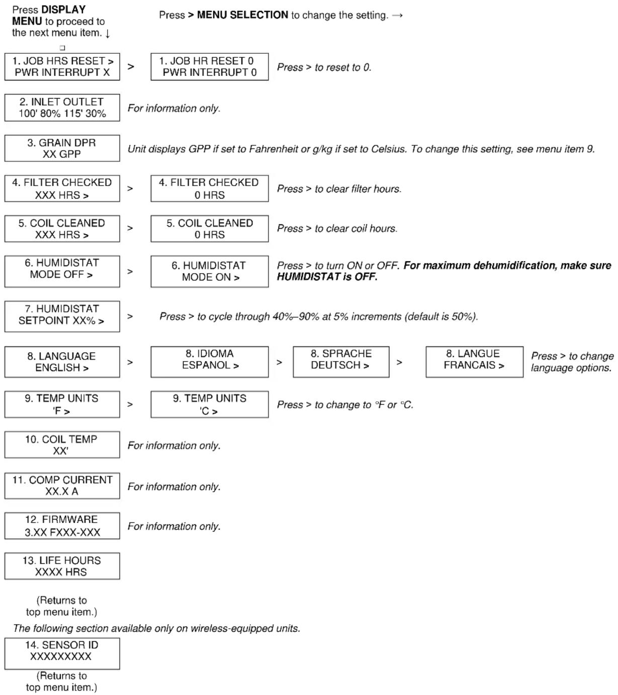
USER SETTINGS
Only menu items followed by a greater-than symbol (>) can be adjusted. If no keys are selected for 5 minutes on screens: INLET OUTLET, GRAIN DPR (INLET-OUTLET for 230V models), the display will return to normal display mode. In all the other menu items, the display with return to the normal display mode after 20 seconds. Items without the symbol (>) are for information only and cannot be changed or reset. See “System Messages” below for additional system status messages.
text_image
Press DISPLAY MENU to proceed to the next menu item. ↓ 1. JOB HRS RESET > PWR INTERRUPT X > 1. JOB HR RESET 0 PWR INTERRUPT 0 Press > to reset to 0. 2. INLET OUTLET 100' 80% 115' 30% For information only. 3. GRAIN DPR XX GPP Unit displays GPP if set to Fahrenheit or g/kg if set to Celsius. To change this setting, see menu item 9. 4. FILTER CHECKED XXX HRS > > 4. FILTER CHECKED 0 HRS Press > to clear filter hours. 5. COIL CLEANED XXX HRS > > 5. COIL CLEANED 0 HRS Press > to clear coil hours. 6. HUMIDISTAT MODE OFF > > 6. HUMIDISTAT MODE ON > Press > to turn ON or OFF. For maximum dehumidification, make sure HUMIDISTAT is OFF. 7. HUMIDISTAT SETPOINT XX% > > Press > to cycle through 40%-90% at 5% increments (default is 50%). 8. LANGUAGE ENGLISH > > 8. IDIOMA ESPANOL > > 8. SPRACHE DEUTSCH > > 8. LANGUE FRANCAIS > Press > to change language options. 9. TEMP UNITS 'F > > 9. TEMP UNITS 'C > Press > to change to °F or °C. 10. COIL TEMP XX' For information only. 11. COMP CURRENT XX.X A For information only. 12. FIRMWARE 3.XX FXXX-XXX For information only. 13. LIFE HOURS XXXX HRS (Returns to top menu item.) The following section available only on wireless-equipped units. 14. SENSOR ID XXXXXXXXX (Returns to top menu item.)AT THE END OF THE JOB
To reduce the possibility of drips when moving the unit, follow these additional steps to ensure that all water is removed from the unit.
NOTICE: The unit will complete the defrost cycle even if the unit is turned off but still plugged in. If the unit is unplugged during the defrost cycle, excessive water may accumulate in the unit and may drip out when you move the unit.
NOTICE: To ensure the condensate tank empties completely while purging, make sure the unit is placed upright on a horizontal surface.
- Do not turn unit off or move it until it has returned to normal operating mode. To confirm unit status, review the control panel. The control panel will display one of the following messages:
Defrost in progress:
--- DEFROST XX
Display mode when unit is in defrost mode. XX indicates the seconds remaining on the defrost cycle.
Shutdown sequence:
WAIT FOR DEFROST XX
Display mode when unit in defrost and unit is powered down (shut off by user). Unit will complete the defrost cycle to remove any built-up ice then purge the pump. XX indicates the seconds remaining on the defrost cycle.
Drying sequence:
WAIT FOR UNIT DRYING XXX
Display mode when unit not in defrost and unit is powered down (shut off by user). Unit will complete the 5 minute drying cycle then purge the pump. XX indicates the seconds remaining on the drying cycle.
Normal display:
UNIT ON XXXX HRS INLET XXX°F / XX%
The unit has completed a defrost and drying cycle and has returned to normal mode. You may now proceed to step 2.
- Gently rock the machine to ensure any water remaining on interior surfaces falls into the sump area.
- Press the PURGE key. When the purge cycle is complete, turn the unit off.
- Remove the external drain hose, drain it carefully, coil it and return it to the storage tray on the top of the unit.
TRANSPORTATION AND STORAGE
IMPORTANT: Before moving, transporting or storing, purge unit and stow hose and power cord as described in the “At the End of the Job” section above.
NOTICE: Handle the unit carefully. Do not drop, throw or place the unit where it could fall. Rough treatment can damage the dehumidifier and may create a hazardous condition or void the warranty.
- Do not expose the control panel to moisture, snow or rain.
- Store and transport securely to avoid any damaging impact to internal parts.
- Secure during transport to prevent sliding and possible injury to vehicle occupants.
- Do not transport or store the unit on its front, sides or back. This will help to prevent any remaining moisture from escaping from the unit or flowing into areas outside the sump.
MAINTENANCE SCHEDULE
WARNING! ELECTRIC SHOCK HAZARD. Unplug the dehumidifier before performing any maintenance.
WARNING: Risk of dust and contaminants exposure. Use of respirator mask and gloves is recommended. If unit has been exposed to potentially dangerous contaminants, clean thoroughly and sanitize before reuse.
NOTICE: The unit is fitted with sensitive electronic sensors. Protect the sensors and their lead wires from damage and do not expose them to water or cleaning solution.
The following tools and supplies are needed to complete the maintenance procedures described in this manual:
Philips screwdriver
T-20 Torx bit
10 mm nutdriver or socket and ratchet
Cleaning cloths
HEPA vacuum cleaner with soft brush nozzle and crevice tool.
Recommended
Cordless drill, small knife, small-jaw pliers, coil cleaning solution, rotomolded housing cleaning solution.
Before each use
Inspect the electrical cord for damage. Look for fraying, cuts, etc. Replace the cord if you find any damage.
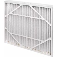
Inspect filter. Replace if accumulation of dust and debris is visible.
NOTICE: Replace used filters only with a new Dri-Eaz filter part no. F579 (24-pack). Other filter types do not provide adequate filtration or airflow. Each filter is individually wrapped to protect filtration effectiveness. Remove the wrapper before installing the filter into the dehumidifier.
Monthly
Inspect coils. Clean when dust accumulation is visible. In normal use, dust can accumulate and can restrict airflow, reducing performance and causing the unit to overheat.
To maintain appearance, wipe interior and exterior surfaces with a damp cloth. For deep cleaning and a
lasting, protective shine, use an automotive interior treatment product.
As Needed
Clean Pump Check Valve and Basin. If the unit displays the message "ER9 PUMP BLOCKED PUMP & HOSE", the pump check valve and pump basin may need to be cleaned. This requires removal of the front housing.
Clean coils. Inspect the horizontal evaporator (cold) coil with the front cover removed. If excessive dust and debris is present, vacuum thoroughly and/or clean with alkaline (non-acidic) coil cleaner.
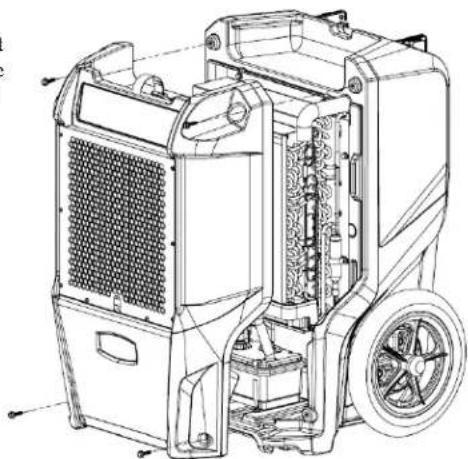
Fig. B: Disassembly for Cleaning
Remove the 4 screws from front housing, and slide off to access coils and pump for service.
natural_image
Technical line drawing of a mechanical device with internal components and mounting holes (no text or symbols)SYSTEM MESSAGES
The Control Panel will display the following messages based on system performance and environmental conditions. User action, if any is required, is indicated in the third column.
| CONTROL PANELMESSAGE | EXPLANATION | USER ACTION |
| INITIALIZING | Unit is powering up. | None |
| FIRMWARE VERSIONXXX | Indicates control board firmware version number. | None |
| FXXX-XXX | Model number. | None |
| OFF | Unit has finished powering up and is operating. | None |
| PLEASE WAITCOMP. DELAY XX | 60s delay before compressor turns on. Allows system pressure to equalize. | None |
| UNIT ON XXXX HRSINLET XXX°F / XX% | First line: indicates total operating hours.Second line: Toggles between inlet temperature and inlet RH every 2 seconds. | None |
| HUMIDISTATINLET XXX°F / XX% | First line: indicates unit is in humidistat modeSecond line: Toggles between inlet temperature and inlet RH every 2 seconds. | None |
| LOW TEMPINLET XXX°F / XX% | Unit shuts off if inlet temp below 45°F/7°C. Turns back on when inlet reaches 50°F/10°C. | None |
| ---PUMP PURGING XX | Displays when the Pump Purge button is pressed.Shows time remaining in seconds. | None |
| HI TEMP CYCLEREMAINING XX MIN | Unit overload limit reached. Cool-down initiated. | None |
| ---DEFROST XXXX | Unit is defrosting, with countdown in seconds. | None |
| WAIT FORDEFROST XXX | Unit turned off when coil is cold or already in a defrost cycle. Proceeds to finish cycle or initiate one to clear the coils of ice before storage. | None |
| WAIT FORUNIT DRYING XXX | Occurs when unit is turned off and coil is not frozen.Clears the coils of water before storage. | None |
| CHECK FILTER >OFF | Prompt to check filter. | Check filter. Press the > key to reset |
| CLEAN COILS >OFF | Prompt to clean coils and interior. | Clean coils. Press the > key to reset |
ERROR MESSAGES
If the control system detects an error, it will produce an error ("ER") message. If this occurs, first unplug the unit and then plug it back in. This will usually reset the electronics, and the unit will begin operating normally. If the error message reappears, refer to the explanations and solutions shown below. If these solutions do not fix the problem, contact your local authorized service center.
| CONTROL PANELMESSAGE | EXPLANATION AND SOLUTION |
| ER4 DEFROSTSENSOR CONNECT-or-ER4 OUTLETSENSOR CONNECT | Temp sensor is open, missing, or shorted. Check that temp sensors are installed correctly on control panel. If error persists, contact service. |
| ER5 SENSORCONNECTION ON BD | Inlet Temp/RH sensor is open, missing, or shorted. Check that inlet temp/RH sensor is installed correctly on control panel and inlet shroud. If error persists, contact service. |
| ER6 CONTACTSERVICE CENTER | Current sensor failure. If error persists, contact service. |
| ER7 INVALIDMODEL SETTING | Incorrect or unsupported DIP switch settings. Contact Dri-Eaz service department for correct DIP switch settings. |
| ER8 BUTTON STUCKALL BUTTONS | Key is stuck or has been held down too long. Contact service. |
| ER9 PUMP BLOCKEDPUMP & HOSE | Check for obstructions. Is the hose kinked under the unit or pinched shut by a wheel? Check the pump for blockage and service if needed. |
TROUBLESHOOTING
| FAULT | CAUSE | SOLUTION |
| Water drips out when moving unit | Unit was unplugged before purging was complete. | Purge unit before moving. See “At the End of the Job.” |
| Unit does not operate | Unit not switched on.No power to machine. | Switch unit on.Plug in unit; check power cord connection at wall outlet and at base of unit. |
| Unit operating, but room not dry | Not enough time to dry.Poor air movement in room.Excessive moist air infiltration. | Make sure “Humidistat” is OFF.Allow more time for drying.Increase air movement with air movers.Seal off area to reduce infiltration. |
| Unit collects too little water | Room air is dry.Room temperature is too low.Filter is full.Coils are clogged. | Make sure “Humidistat” is OFF.Confirm humidity level with hygrometer.Increase room temperature.Check filter. Replace as necessary.Check coils. Clean as necessary. |
| If the problem you are experiencing is not listed here, call your local distributor or contact our Service Department at 800-932-3030 for further assistance. | ||
SPECIFICATIONS
| Model | LGR 6000Li (F600) |
| Water removal AHAM (80°F/60% RH) | 100 pts. | 47.3 L / day |
| Water removal saturation (90°F/90% RH) | 204 pts. | 96.5 L / day |
| Process air (max.) | 320 CFM |
| Dimensions (H × D × W) | 32.1 × 19.8 × 20.0 in.81.5 × 50.3 × 50.8 cm |
| Weight | 103 lbs. | 46.7 kg |
| Amps | 6.6A |
| Volts | 115V |
| Frequency | 60Hz |
| Power | 759W |
| Operating range | 33°F–100°F | 1°C–38°C |
| Noise level (avg.) | 53 dB |
| Drain hose | 40 ft. | 12.2 m |
| Power cord | 25 ft. | 7.6 m |
| Construction | Rotomolded shell |
| Safety | ETL certified CSA 22.2 no. 92 |
| Specifications are subject to change without notice. Some values may be approximate.*Fan speed varies automatically for optimized performance. | |
Order replacement air filters from your local distributor. Part no. F579 (24 pack).
Warranty information is available at www.LegendBrandsRestoration.com.
Be sure to visit LegendBrandsRestoration.com/Warranty and register your purchase. Your registration will help us provide you with updated product information as needed.
For proper disposal, this unit should be taken to a recycler licensed to process refrigeration equipment.
WARNING: This product and other substances that may become airborne from its use contain chemicals, including lead and phthalates, known to the State of California to cause cancer, birth defects, or other reproductive harm. For more information, go to P65Warnings.ca.gov
15180 Josh Wilson Road, Burlington, WA 98233
Teléfono: 800-932-3030 Fax: 360-757-7950 www.LegendBrandsRestoration.com
natural_image
Three black-and-white icons representing hand gestures and firecrackers (no text or symbols)text_image
Technical diagram of a portable air purifier with labeled components and partsPARTE POSTERIOR
natural_image
Technical line drawing of a mechanical device with internal components and mounting brackets (no text or symbols)15180 Josh Wilson Road, Burlington, WA 98233
Téléphone : 800-932-3030 Fax : 360-757-7950 www.LegendBrandsRestoration.com