PHD 200 - Air purifier Dri Eaz - Free user manual and instructions
Find the device manual for free PHD 200 Dri Eaz in PDF.
User questions about PHD 200 Dri Eaz
0 question about this device. Answer the ones you know or ask your own.
Ask a new question about this device
Download the instructions for your Air purifier in PDF format for free! Find your manual PHD 200 - Dri Eaz and take your electronic device back in hand. On this page are published all the documents necessary for the use of your device. PHD 200 by Dri Eaz.
USER MANUAL PHD 200 Dri Eaz
Owner's Manual PHD 200 Dehumidifier
Model #103806 (F515)
LEGEND BRANDS, INC.
15180 Josh Wilson Road, Burlington, WA 98233
Phone: 800-932-3030 Fax: 360-757-7950 CrawlspaceDry.com
The Legend Brands® PHD 200 Dehumidifier reduces humidity in enclosed environments by removing water vapor from the air. The PHD 200 is ideal for crawlspace drying, humidity control and other applications requiring high-performance dehumidification. (Not intended for professional water damage restoration.)
Patents: LBpatents.com
READ AND UNDERSTAND BEFORE OPERATING
WARNING
natural_image
Three black-and-white icons representing hand gestures and foot positions (no text or symbols)SAFETY INSTRUCTIONS
WARNING! Do not alter or modify your unit in any way. Use only replacement parts authorized by Legend Brands, Inc. Modifications or use of unapproved parts could create a hazard and will void your warranty. Contact your authorized distributor for assistance.
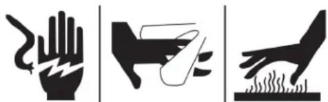
CORRECT PLUG REMOVAL
Grasp IEC plug and pull straight out
IMPORTANT: Damage to IEC receptacle or dehumidifier resulting from improper removal of the power cord is not covered by warranty. The IEC power cord is a wear item and is not covered by warranty.
natural_image
Hand inserting a plug into an outlet (no text or symbols visible)WARNING! Electric shock hazard, rotating fan, hot surface hazards. Unplug unit before opening cover for cleaning or servicing. Unit must be grounded.
- Inspect the power cord before use. If cord is damaged, do not use. Always grasp the plug (not the cord) to unplug.
- Insert three-prong plug on power cord into a matching electrically grounded outlet. Do not use adapter. Never cut off third prong. Do not use an extension cord.
- The unit must be operated on a 115V/60Hz circuit protected by a Ground Fault Circuit Interrupter (GFCI) device.
- Keep motor and wiring dry.
- Do not attempt to repair the unit. For Authorized Service Centers, contact Legend Brands.
NOTICE: Do not use in environments where corrosive chemicals are present, such as chlorine.
BEFORE YOU BEGIN
Warranty registration
Visit warranty.LegendBrandsRestoration.com to register your purchase. Registration allows us to better assist you with using, maintaining or servicing your equipment and to contact you in case we have important safety information concerning your Legend Brands product. If you determine service is required, have your equipment model, serial number and original proof of purchase available and call your distributor for assistance with obtaining a return material authorization (RMA).
INTRODUCTION
The PHD 200 Dehumidifier reduces humidity in enclosed structural environments by removing water vapor from the air. With proper use, the PHD 200 can help to dry out damp structural materials, insulation, and contents, and maintain a healthy level of humidity. Using the PHD 200 may also prevent secondary damage caused by high humidity.
How the PHD 200 works
The PHD 200 refrigerant dehumidifier uses a fan to draw moist air in and condenses it into water that collects in a tray and is automatically pumped out through a drain hose.
The PHD 200 is preset to automatically maintain a 50% RH level. To change this setting, see “Humidistat Mode” below. Note: Unit automatically shuts off below 40% RH.
CONTROLS AND OPERATING INSTRUCTIONS
Set unit upright
NOTICE: Always store, transport, and use the unit in a horizontal position. If the unit is ever placed in a vertical position, return it to the horizontal position and let it stand for at least 30 minutes before turning it on.
Positioning a Dehumidifier
For best results, operate your dehumidifiers in an enclosed area. Place your dehumidifier away from obstructions, and keep it away from anything that could block airflow into and out of the unit. For more information about creating an optimum drying environment, contact Legend Brands at 800-932-3030.
TIP: Before installing in a crawlspace or other difficult to access location, plug in the unit and run it for approximately half an hour to ensure proper operation.
Set up drain hose
The PHD 200 condensate pump connects to a plastic drain hose equipped with a quick-connect fitting for quick attachment to the unit. To set up the hose, unwrap the entire hose and place the unattached end in a sink, drain, bucket or outdoors – anywhere that water can drain out safely. Connect the other end of the hose to the PHD 200. If you use a bucket or other container for water collection, check it regularly to prevent overflows.
NOTICE: Uncoil and straighten the entire drain hose. Do not leave any part of the hose coiled and do not place the end of the hose higher than 3 ft. (1 m) above the bottom of the unit. Also check for kinks or other obstructions that might restrict the flow of water. Obstructions may cause a water backup and result in overflows.
Plug in electrical cord
The PHD 200 should be plugged into a GFCI-protected 115 volt outlet rated for at least 15 amps. Always plug the cord firmly into the unit first, and then plug the other end into a suitable outlet.
Startup display and normal display modes
When unit is first plugged in to AC power, the control panel display will briefly cycle through a series of
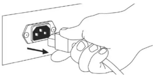
Fig. A: Parts Identification
text_image
Air inlet Control panel Air outlet Power socket Temp/RH sensor Remove/Insert air filter here. Condensate drain quick- connectreadouts. This is part of the unit's self-diagnosis procedure and no user intervention is required.
HOW TO USE THE CONTROL PANEL
The i-Series Controller provides comprehensive dehumidifier controls and detailed real-time data about the drying environment as well as job hours, self-diagnosis messages, maintenance reminders and operating status.
For detailed information and additional instructions, please visit the i-Series Controller page at Controller.LegendBrandsRestoration.com
Home Screen Views
Unit OFF
Unit must be plugged in.
Top display bar:
Job hours, current time

Press MENU to access settings and configuration controls

Press PURGE to pump out condensate tank

Press ON/OFF to turn unit on.
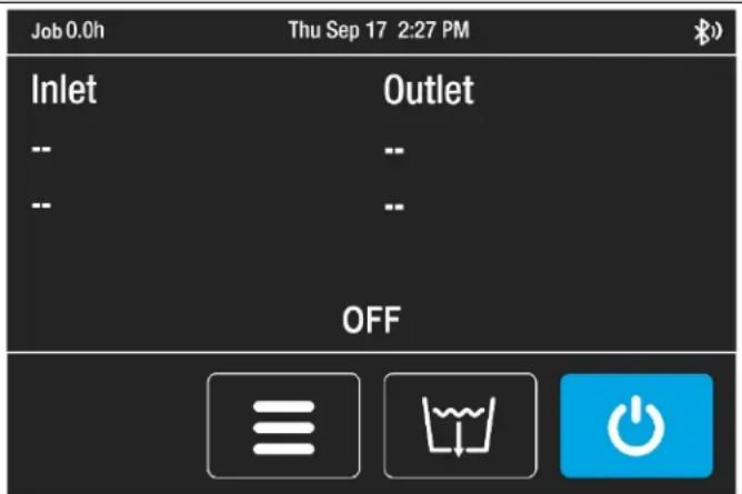
text_image
Job 0.0h Thu Sep 17 2:27 PM Inlet Outlet -- -- -- -- OFFUnit ON
Press ON/OFF key to switch unit on.
Top display bar:
Job hours, current time
Information display:
Inlet/Outlet temp, %RH and GPP
Current GPP removal
Bottom menu bar:

Quick-Reference Inlet GPP.
1: < 60 GPP; 2: 60–90 GPP; 3: > 90 GPP

Press MENU to access settings and configuration controls
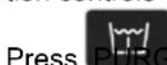
Press ON/OFF to turn unit off.
text_image
Job 0.0h Thu Sep 17 2:27 PM Inlet Outlet 80.0°F 60% 107.1°F 48% 91 GPP 67 GPP Δ24 GPPFor detailed control panel instructions, please visit the i-Series Controller product page at Controller.LegendBrandsRestoration.com
If the control system detects a problem, it will display an "Alert" symbol in the upper right corner of the screen. Press ON/OFF to view the message and OK to clear the message. NOTE: In the case of an error, the unit will not operate until the problem is resolved. Refer to the explanations and solutions shown below. If these solutions do not fix the problem, contact your local authorized service center for further assistance.
| CONTROL PANELMESSAGE | EXPLANATION AND SOLUTION |
| ER4 ErrorDefrost Thermistor Connect-or-ER4 ErrorOutlet Thermistor Connect | Temp sensor is open, missing, or shorted. Check that temp sensors are in-stalled correctly on control panel. If error persists, contact service. |
| ER5 ErrorInlet RH1 Temp/RH Sensor | Inlet Temp/RH sensor is open, missing, or shorted. Check that inlet temp/RH sensor is installed correctly on control panel and inlet shroud. If error persists, contact service. |
| ER5 ErrorInlet RH1 Temp/RH Sensor | Inlet Temp/RH sensor is open, missing, or shorted. Check that inlet temp/RH sensor is installed correctly on control panel and inlet shroud. If error persists, contact service. |
| ER6 ErrorCurrent Sensor Failure | Current sensor failure. If error persists, contact service. |
| ER9 ErrorPump Blocked | Check for obstructions in drain hose. Check the pump. |
| W1Low BATTERY | Replace coin cell battery (3V, CR2032) on control panel. |
| W2BLE ErrorW3Flash ResetW4WDT Reset | Cycle power to dehumidifier. If warning persists, contact service. |
BEFORE MOVING THE UNIT
To reduce the possibility of drips when moving the unit, follow these additional steps to ensure that all water is removed from the unit.
NOTICE: To ensure all water is removed from the dehumidifier, the unit will complete the defrost cycle even if the unit is turned off. If the unit is unplugged during the defrost cycle, excessive water may accumulate in the unit and may drip out when you move the unit.
NOTICE: To ensure the condensate tank empties completely while purging, make sure the unit is placed up-right on a horizontal surface.
- If the unit is in a defrost cycle, wait until the unit has returned to normal operating mode before proceeding.
- Gently rock the machine to ensure any water remaining on interior surfaces falls into the sump area.
- Press the PURGE key. When the purge cycle is complete, turn the unit off.
- Remove the external drain hose, drain it carefully, coil it and secure it with one of the straps provided on the side of the unit.
- Remove the power cord, coil it neatly, and secure it with one of the straps provided.
TRANSPORTATION AND STORAGE
NOTICE: Always remove power cord before moving, transporting, or storing the unit.
NOTICE: Handle the unit carefully. Do not drop, throw, or place the unit where it could fall. Rough treatment can damage this equipment and may create a hazardous condition or void warranty.
- Do not expose the control panel to moisture, snow or rain.
- Protect from freezing.
- Store and transport securely to avoid any damaging impact to internal parts.
- Secure during transport to prevent sliding and possible injury to vehicle occupants.
MAINTENANCE SCHEDULE
WARNING! ELECTRIC SHOCK HAZARD. Unplug unit before cleaning or servicing.
WARNING: Risk of dust and contaminants exposure. Use of respirator mask and gloves is recommended. If unit has been exposed to potentially dangerous contaminants, clean thoroughly and sanitize before reuse.
NOTICE: The unit is fitted with sensitive electronic sensors. Protect the sensors and their lead wires from damage and do not expose them to water or cleaning solution.
The following tools and supplies are needed to complete the maintenance procedures described in this manual:
Philips screwdriver
10 mm wrench
6 mm hex bit
14 in. nut driver
Cleaning cloths
HEPA vacuum cleaner with soft brush nozzle and crevice nozzle.
Recommended
Cordless drill, small knife, small-jaw pliers, coil cleaning solution, rotomolded housing cleaning solution.
Before each use
Inspect the electrical cord for damage. Look for fraying, cuts, etc. Replace the cord if you find any damage.
Inspect filter. The PHD 200 filter should be replaced when the accumulation of dust is visible.
Monthly
Clean pump check valve and basin. In normal use, dust can accumulate and can restrict airflow, reducing performance and causing the unit to overheat. Clean when dust accumulation is visible. Remove grills and cover as shown in Fig. B. Use a vacuum cleaner with a brush tool and a soft cloth to remove any debris. Take care not to damage any interior components.
To maintain appearance, wipe interior and exterior surfaces with a damp cloth. For deep cleaning and a lasting, protective shine, use an automotive interior cleaner.
As Needed
Clean pump check valve and basin. Remove grills and cover as shown in Fig. B. Remove screws from pump base and lift out pump. Wipe out pump basin with a damp cloth. Unthread barbed fitting with check valve and rinse fitting and check valve with clean water. Reinstall barbed fitting into pump. Do not overtighten. Reinstall pump on base. Reinstall cover and grills.
Clean coils. With the cover removed, inspect both coils. If excessive dust and debris is present, vacuum thoroughly and/or clean with coil cleaner.
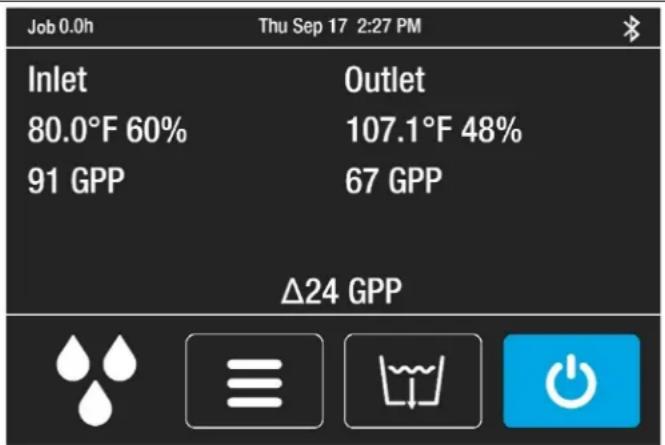
Fig. B: Disassembly for Cleaning
Remove the 4 screws from housing and 2 top screws each from inlet and outlet grills and lift off cover.
natural_image
Technical line drawing of an internal combustion engine assembly with fan and cooling unit (no text or labels)TROUBLESHOOTING
| FAULT CAUSE SOLUTION | ||
| Water drips out when moving unit | Unit was unplugged before purging was complete. | Purge unit before moving. See “Before Moving the Unit,” p. 4. |
| Unit does not operate | Unit not switched on.No power to machine. | Switch unit on.Plug in unit; check power cord connection at wall outlet and at base of unit. |
| Unit operating, but room not dry | Not enough time to dry.Poor air movement in room.Excessive moist air infiltration. | Allow more time for drying.Increase air movement with air movers.Seal off area to reduce infiltration. |
| Unit collects too little water | Room air is dry.Room temperature is too low.Air filter is full.Heat exchange block and/or coils are clogged. | Confirm humidity level with hygrometer.Increase room temperature.Check filter. Clean or replace as necessary.Check heat exchange block and coils. Clean as necessary. |
| If the problem you are experiencing is not listed here, call your local distributor. | ||
SPECIFICATIONS
| Name | PHD 200 DehumidifierModel #103806 (F515) |
| Dimensions (W × H × D) | 12.5 × 17.6 × 21.5 in.31.8 × 44.7 × 54.6 cm |
| Weight (w/ cord & hose) | 65 lbs. | 29.5 kg |
| Amps | 6.2 amps at 80°F/60% RH |
| Power | 115V / 60Hz |
| Air movement | 180 CFM | 305 CMH |
| Water removal | 74 pts/day | 35 L/dayat 80°F/60% RH (AHAM)120 pts/day | 57 L/dayat 90°F/90% RH |
| Operating temperature range | 45°F–100°F | 7°C–38°C |
| Specifications are subject to change without notice. Some values may be approximate. | |
PARTS INCLUDED
20 ft. (6 m) of drain hose with quick-connect fitting.
6 ft. (1.8 m) detachable power cord.
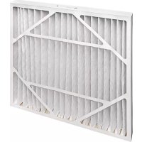
1 disposable air filter. Reorder 3-pack #116689 (F527)
3-pack
OPTIONAL
Duct Attachment Kit #106996 (F530)
Hanging Kit #106773 (F526)
FOR PARTS AND SERVICE CALL YOUR LOCAL DISTRIBUTOR or Legend Brands at 800-932-3030.
LegendBrandsRestoration.com
Visit warranty.LegendBrandsRestoration.com and register your purchase to ensure you receive any important product releases.

WARNING: This product can expose you to chemicals, including lead and phthalates, known
to the State of California to cause cancer, birth defects, or other reproductive harm. For more information, go to P65Warnings.ca.gov
15180 Josh Wilson Road, Burlington, WA 98233
natural_image
Three black-and-white icons representing hand gestures and foot positions (no text or symbols)natural_image
Illustration of a hand inserting an electrical plug into a cable (no text or symbols)natural_image
Technical line drawing of an electronic device with internal components and fan assembly (no text or labels)15180 Josh Wilson Road, Burlington, WA 98233
Téléphone : 800-932-3030 Fax : 360-757-7950 CrawlspaceDry.com