
ZONE X 1208 - Processor LD Systems - Free user manual and instructions
Find the device manual for free ZONE X 1208 LD Systems in PDF.
| Brand | LD Systems |
| Model | ZONE X 1208 |
| Product type | DSP audio matrix for fixed installations |
| Audio inputs | 12 balanced mic/line inputs (3-pin terminal block, pitch 3.81 mm) + 1 audio input on remote control bus |
| Audio outputs | 8 balanced line outputs (3-pin terminal block, pitch 3.81 mm) |
| Logic inputs (GPI) | 8 GPI ports (activation by grounding, 3-pin terminal block) |
| Logic outputs (GPO) | 8 GPO ports (LED mode 3 mA or sink 300 mA, 3-pin terminal block) |
| Phantom power | +48 VDC / 500 mA (selectable per channel) |
| Connectors | Audio inputs/outputs: 3-pin terminal block (pitch 3.81 mm); Ethernet RJ45, Micro-USB B, remote control bus output RJ45; Dante option: primary + secondary Ethernet input RJ45 |
| DSP | Analog Devices dual-core SHARC+ processor + ARM Cortex A5, 40-bit floating point |
| A/D - D/A converter | 32-bit |
| Sampling frequency | 48 kHz |
| System latency | 4.3 ms |
| Frequency response | 15 Hz – 22 kHz (+/-0.15 dB) |
| Signal-to-noise ratio | > 117 dB (at +20 dBu, gain 0 dB, A-weighted) |
| Total harmonic distortion (THD+N) | < 0.003 % (line input/output, +13 dBu, 20 Hz-20 kHz, gain 0 dB) |
| Power supply | 90 – 240 V~, 50/60 Hz (switching) |
| Power consumption | 23 W (standby), 60 W (max.) |
| Fuse | T2.5 AL / 250 V |
| Dimensions (W × H × D) | 483 × 44.5 × 315 mm (including terminal blocks); required rack depth: 350 mm |
| Weight | 3.8 kg |
| Operating temperature | 0 °C to +40 °C (max. 60% RH) |
| Cooling | Passive convection |
| Control software | Xilica Designer (Windows 7+ / macOS 10.8+); iOS/Android apps |
| Dante extension | Optional: 64×64 audio-over-IP card (model D) |
Frequently Asked Questions - ZONE X 1208 LD Systems
User questions about ZONE X 1208 LD Systems
0 question about this device. Answer the ones you know or ask your own.
Ask a new question about this device
Download the instructions for your Processor in PDF format for free! Find your manual ZONE X 1208 - LD Systems and take your electronic device back in hand. On this page are published all the documents necessary for the use of your device. ZONE X 1208 by LD Systems.
USER MANUAL ZONE X 1208 LD Systems
SAFETY INFORMATION 3
FEATURES
PACKAGING CONTENT 5
CONNECTIONS, CONTROLS AND DISPLAY ELEMENTS 5
CONNECTING DEVICES 6
XILICA DESIGNER SOFTWARE 8
STARTING THE SOFTWARE 10
NETWORK VIEW 10
FIRMWARE UPGRADE 11
FIRMWARE UPGRADE PROCEDURE 11
PROJECT VIEW 14
DESIGN
ONLINE MODE 18
GPI/D-CONNECTION EXAMPLES 24
TECHNICAL DATA 25
MANUFACTURER'S DECLARATIONS 27
DEUTSCH
We have designed this product to operate reliably over many years. LD Systems stands for this with its name and many years of experience as a manufacturer of high-quality audio products. Please read this User's Manual carefully, so that you can begin making optimum use of your LD Systems product quickly.
You can find more information about LD-SYSTEMS at our Internet site WWW.LD-SYSTEMS.COM
SAFETY INFORMATION
- Please read these instructions carefully.
- Keep all information and instructions in a safe place.
- Follow the instructions.
- Observe all safety warnings. Never remove safety warnings or other information from the equipment.
- Use the equipment only in the intended manner and for the intended purpose.
- Use only sufficiently stable and compatible stands and/or mounts (for fixed installations). Make certain that wall mounts are properly installed and secured. Make certain that the equipment is installed securely and cannot fall down.
- During installation, observe the applicable safety regulations for your country.
- Never install and operate the equipment near radiators, heat registers, ovens or other sources of heat. Make certain that the equipment is always installed so that is cooled sufficiently and cannot overheat.
- Never place sources of ignition, e.g., burning candles, on the equipment.
- Ventilation slits must not be blocked.
- Do not use this equipment in the immediate vicinity of water (does not apply to special outdoor equipment - in this case, observe the special instructions noted below. Do not expose this equipment to flammable materials, fluids or gases. Avoid direct sunlight!
- Make certain that dripping or splashed water cannot enter the equipment. Do not place containers filled with liquids, such as vases or drinking vessels, on the equipment.
- Make certain that objects cannot fall into the device.
- Use this equipment only with the accessories recommended and intended by the manufacturer.
- Do not open or modify this equipment.
- After connecting the equipment, check all cables in order to prevent damage or accidents, e.g., due to tripping hazards.
- During transport, make certain that the equipment cannot fall down and possibly cause property damage and personal injuries.
- If your equipment is no longer functioning properly, if fluids or objects have gotten inside the equipment or if it has been damaged in anot her way, switch it off immediately and unplug it from the mains outlet (if it is a powered device). This equipment may only be repaired by authorized, qualified personnel.
- Clean the equipment using a dry cloth.
- Comply with all applicable disposal laws in your country. During disposal of packaging, please separate plastic and paper/cardboard.
- Plastic bags must be kept out of reach of children.
- Please note that changes or modifications not expressly approved by the party responsible for compliance could void the user's authority to operate the equipment.
FOR EQUIPMENT THAT Connects TO THE POWER MAINS
- CAUTION: If the power cord of the device is equipped with an earthing contact, then it must be connected to an outlet with a protective ground. Never deactivate the protective ground of a power cord.
- If the equipment has been exposed to strong fluctuations in temperature (for example, after transport), do not switch it on immediately. Moisture and condensation could damage the equipment. Do not switch on the equipment until it has reached room temperature.
- Before connecting the equipment to the power outlet, first verify that the mains voltage and frequency match the values specified on the equipment. If the equipment has a voltage selection switch, connect the equipment to the power outlet only if the equipment values and the mains power values match. If the included power cord or power adapter does not fit in your wall outlet, contact your electrician.
- Do not step on the power cord. Make certain that the power cable does not become kinked, especially at the mains outlet and/or power adapter and the equipment connector.
- When connecting the equipment, make certain that the power cord or power adapter is always freely accessible. Always disconnect the equipment from the power supply if the equipment is not in use or if you want to clean the equipment. Always unplug the power cord and power adapter from the power outlet at the plug or adapter and not by pulling on the cord. Never touch the power cord and power adapter with wet hands.
- Whenever possible, avoid switching the equipment on and off in quick succession because otherwise this can shorten the useful life of the equipment.
- 10RANTIN: Replace fuses only with fuses of the same type and rating. If a fuse blows repeatedly, please contact an authorised service centre.
- To disconnect the equipment from the power mains completely, unplug the power cord or power adapter from the power outlet.
- If your device is equipped with a volex power connector, the mating volex equipment connector must be unlocked before it can be removed. However, this also means that the equipment can slide and fall down if the power cable is pulled, which can lead to personal injuries and/or other damage. For this reason, always be careful when laying cables.
- Unplug the power cord and power adapter from the power outlet if there is a risk of a lightning strike or before extended periods of disuse.
- The appliance is not to be used by persons (including children) with reduced physical, sensory or mental capabilities, or lack of experience and knowledge.
- Children must be instructed not to play with the device.
- If the power cord of the device is damaged, do not use the device. The power cord must be replaced by an adequate cable or assembly from an authorized service center.

CAUTION: To reduce the risk of electric shock, do not remove cover (or back). There are no user serviceable parts inside. Maintenance and repairs should be exclusively carried out by qualified service personnel.
The warning triangle with lightning symbol indicates dangerous uninsulated voltage inside the unit, which may cause an electrical shock.

The warning triangle with exclamation mark indicates important operating and maintenance instructions.
Warning! This symbol indicates a hot surface. Certain parts of the housing can become hot during operation. After use, wait for a cool-down period of at least 10 minutes before handling or transporting the device.

Warning! This device is designed for use below 2000 metres in altitude.

Warning! This product is not intended for use in tropical climates.
CAUTION! HIGH VOLUMES IN AUDIO PRODUCTS!
This device is meant for professional use. Therefore, commercial use of this equipment is subject to the respectively applicable national accident prevention rules and regulations. As a manufacturer, Adam Hall is obligated to notify you formally about the existence of potential health risks. Hearing damage due to high volume and prolonged exposure: When in use, this product is capable of producing high sound-pressure levels (SPL) that can lead to irreversible hearing damage in performers, employees, and audience members. For this reason, avoid prolonged exposure to volumes in excess of 90 dB.
NOTE: This equipment has been tested and found to comply with the limits for a Class B digital device, pursuant to Part 15 of the FCC Rules. These limits are designed to provide reasonable protection against harmful interference in a residential installation. This equipment generates uses and can radiate radio frequency energy and, if not installed and used in accordance with the instructions, may cause harmful interference to radio communications. However, there is no guarantee that interference will not occur in a particular installation. If this equipment does cause harmful interference to radio or television reception, which can be determined by turning the equipment off and on, the user is encouraged to try to correct the interference by one or more of the following measures:
- Reorient or relocate the receiving antenna.
- Increase the separation between the equipment and receiver.
- Connect the equipment into an outlet on a circuit different from that to which the receiver is connected.
- Consult the dealer or an experienced radio/TV technician for help.
FEATURES
Hybrid architecture DSP processor
- DSP templates available for different installation requirements
- 40-bit floating point DSP engine with analog devices dual core SHARC+ and ARM Cortex A5 processor
- New generation Linux operating system
- Premium grade microphone preamps and high-performance 32 bit AD/DA converters
- 12 balanced mic/line inputs with 48V phantom power selection per input
- 8 balanced outputs
- 8 GPI and 8 GPO logic ports
- 6-pole terminal block connectors (pitch 3.81mm ) for all audio and control inputs/outputs
- REMOTE bus for integration with wall panels and paging microphones from LD Systems
- Clean and intuitive front panel design
- Ethernet interface for remote control via the universal control software Xilica Designer
- Remote control apps available in both iOS and Android, for custom user panels
- Integrated event scheduler
- Optional 64x64 Dante expansion (audio over IP connectivity)
- 19" rack device, 1 RU
PACKAGING CONTENT
- LD ZoneX hardware
- Power cable
- User manual
CONNECTIONS, CONTROLS AND DISPLAY ELEMENTS

FRONT
1 GLOBAL STATUS LEDs
POWER = device is powered on
NETWORK = network connection established
REMOTE = LD Systems remote devices connected
(paging microphones, control panels, etc)
2 INPUT 6 OUTPUT LEDs
White = Signal present
Red = Signal overdriven


BACK
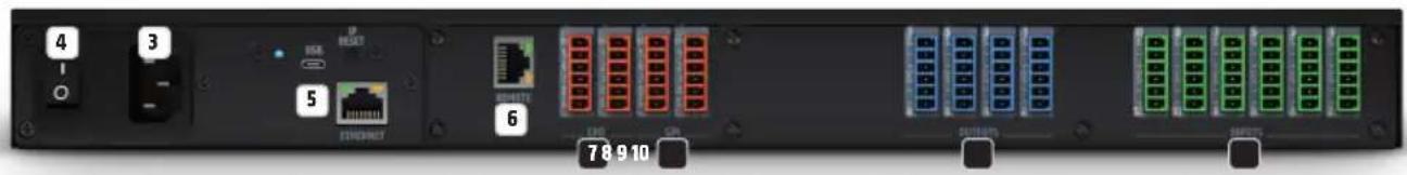
3 POWER CONNECTOR AND FUSE HOLDER
IEC power connector with fuse holder. The packaging content includes a suitable power cable.
CAUTION: Only replace the fuse with another of the same type and with the same ratings. See information on the housing. If the fuse repeatedly blows, please contact an authorised service centre.
4 ON/OFF SWITCH
Rocker switch to turn the device on and off.
ETHERNET-USB-RESET
Communication expansion card with Ethernet connector, or Ethernet + Dante (64 x 64 I/O) on "D" model, for communication between the ZoneX processor and the host computer, Micro USB recovery port for firmware recovery and IP reset button.
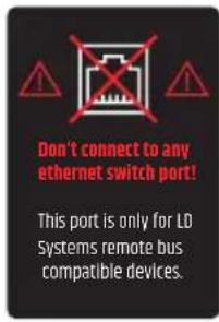
6 REMOTE
LD Systems remote bus for the integration with future control panels and paging microphones from LD Systems. Please note that this connector only supports LD Systems remote bus-compatible devices and not Ethernet switch ports!
GPO
8 GPO outputs (logic ports) with two selectable modes per output: LED (3 mA) or sink (300 mA). 3-pole terminal blocks (pitch 3.81 mm). Please also note the connection examples in this user manual (see GPI/0 - CONNECTION EXAMPLES)
8GPI
8 GPI inputs (logic ports), with short to ground activation. 3-pole terminal blocks (pitch 3.81mm ). Please also note the connection examples in this user manual (see GPI/0 - CONNECTION EXAMPLES)
9 OUTPUTS
8 balanced audio outputs. 3-pole terminal blocks (pitch 3.81mm
10 INPUTS
12 balanced audio mic/line inputs with switchable 48V phantom power per channel. 3-pole terminal blocks (pitch 3.81 mm).
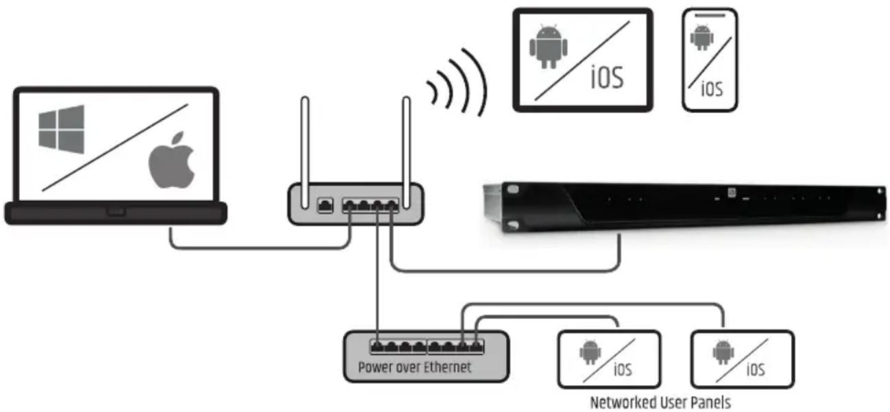
CONNECTING DEVICES
LD Systems ZoneX DSP processor and other control units run on a network-based infrastructure and are configured and controlled via a computer with the xilica Designer software.
PREREQUISITES FOR OPERATION
- Computer
Network interface (router, PoE switch)
A router is required for the IP address assignment and quick and easy connection to your computer and connected control units. A PoE switch is required for control units without local power supply.
- Ethernet cable. All wired connections use a standard RJ45 Ethernet cable (Cat 5e or better).
A NETWORK CONNECTION BETWEEN HOST COMPUTER AND ZONEX PROCESSOR CAN BE CREATED AS FOLLOWS:
A. ROUTER WITH ACTIVATED DHCP SERVER (RECOMMENDED)
When using a router with an enabled DHCP server, the ZoneX processor automatically acquires the IP address during start-up, as soon as the connection exists. It is recommended to use a router and PoE switch if further control units/controllers from other manufacturers are connected to the network. This combination provides a DHCP server and also facilitates the power supply for the connected devices. We recommend using Linksys routers and Netgear switches.
Note: Routers/switches with activated DHCP server should generally be switched on first. And all Ethernet cables should be connected to the hardware before the devices are switched on. This will allow for a correct IP address assignment.
- First, turn on the router/swi tch.
- Then connect the host computer to a DHCP enabled router via an Ethernet cable.
- Connect the router to the ZoneX processor via an Ethernet cable.
- Connect the ZoneX processor to the mains and switch it on.
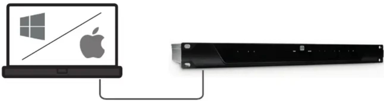
B. NON-DHCP-BASED DIRECT CONNECTION OR INDIRECT CONNECTION VIA ETHERNET SWITCH
If the processor is directly connected to a computer or indirectly via a switch and no DHCP server is available, the connection cannot be established automatically.
Therefore, non-DHCP-based connections must be configured manually. Further details can be found in the xilica Designer help file or in the LD Systems ZoneX FAQ.
XILICA DESIGNER SOFTWARE
The xilica Designer software not only enables a detailed configuration of the Zonex processor, but also offers access to the configuration of third-party remote control units, facilitates the management of optional Dante network devices and provides universal third-party device control integration.
MAC OS X INSTALLATION
System requirements:
Mac OS X 10.8 or higher
- 1 GHz processor or higher
- 500 MB free hard disk space
- 1GB graphics card
- 4GB RAM
- Download the latest version of Xilica Designer software to your computer from the LD Systems website (www.Id-systems.com).
- Open the downloaded.zip file.
- Then open the file xilicaDesigner.mpgk.
- An installation window now appears. Follow the individual steps.
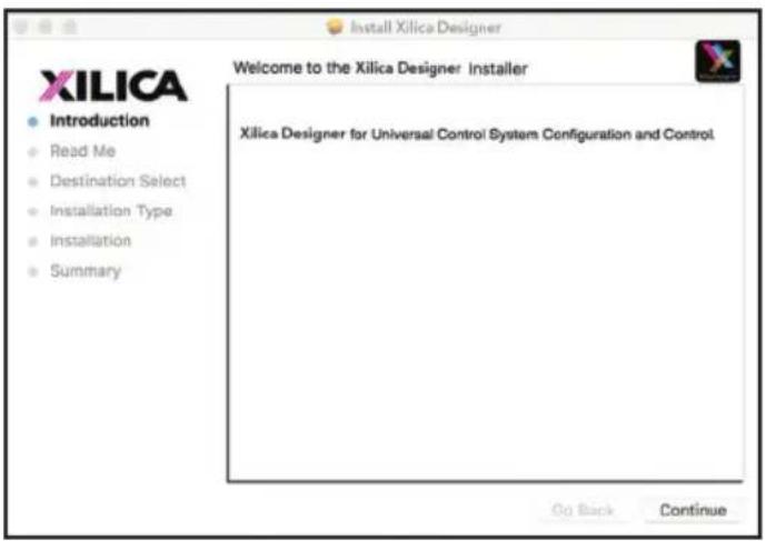
- If the installation process is successful, the installation window displays the message: "The installation was successful".
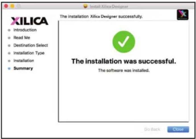
- The Xilinx Designer software is now installed.
WINDOWS INSTALLATION
System requirements:
- Windows 7 or higher
- 1 GHz processor or higher
- 500 MB free hard disk space
- 1GB graphics card
-
4GB RAM
-
Download the latest version of Xilica Designer software to your computer from the LD Systems website (www.Id-systems.com).
- Open the downloaded.zip file.
- Then open the file XilicalDesigner.exe.
- An installation window nor appears. Click "Install" to continue.
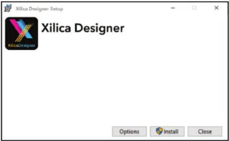
- Wait until the installation process is complete. This may take a few minutes.
- If the installation process is successful, Windows asks you for permission to allow firewall access. We recommend setting up the system so that communication for Xilica Designer is authorized on private networks such as home or business networks. Public networks can be included if required.
Select the desired options via the control panel and then click on "Allow Access" to complete the configuration.
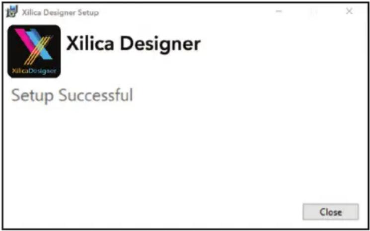
- The xilica Designer software is now installed.
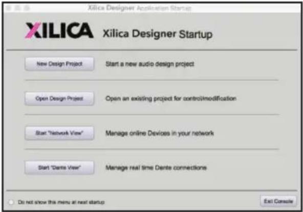
STARTING THE SOFTWARE
Find the xilica Designer software on your desktop or in the application folder. Double-click the software to start it. You can now create a new design project or open a design project, start the network view, or start the Dante view.
NETWORK VIEW
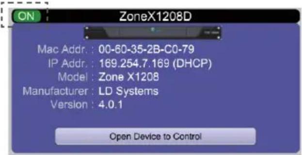
The network view displays all processors and control units on the network. Here you can find device information such as connection status, computer IP address, device IP address, Mac address, device name, manufacturer and firmware version.
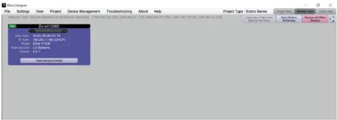
The connected processor(s) should be visible in network view. There is a connection status indicator in the top left corner of each device block.
Green: The device is connected and ready for operation.
Yellow: The device is connected and online but is not ready for operation. Move the cursor over the network indicator, and a pop-up window will display a message with information about the detected problem. (The message usually says that no device design is loaded).
Red: The device is not connected and is offline. There is no communication between Xilica Designer software and the device. Please check all cables and connections and make sure that the device is switched on. If the processor is performing a firmware upgrade or restarting, there may be a temporary interruption.
From time to time, you may see an exclamation mark (!). This means that a firmware upgrade is available. This does not normally require immediate intervention, but the project file does not contain updated models since the earlier firmware is not supported. Further details can be found in the Xilinx Designer help file or in the LD Systems ZoneX FAQ.
FIRMWARE UPGRADE
Please note that the use of an old software version with new firmware or the use of new software with old firmware works in principle but the range of functions may be limited or the functionality may not be optimal in all cases.
We recommend always using the latest versions of software and firmware.
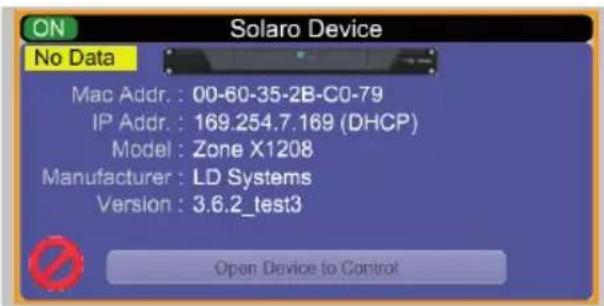
Before you start, check the software and firmware versions.
To check the device's firmware version, ensure that your device is switched on and online. The network view marks devices available for a firmware upgrade with a yellow triangle using an exclamation mark. In addition, the device's firmware version is also listed in the device block for the respective device.
The current software version is displayed when you click on About in the menu in the top bar.
FIRMWARE UPGRADE PROCEDURE
Save the device's design file on your computer as all programmed data will be deleted from the device during the upgrade. When the firmware upgrade is complete, the design file can be reloaded on the device.
- The device must be online and ready for operation to perform a firmware upgrade.
The newest firmware version for the corresponding Zone X model can be downloaded from the LD Systems website (www.Id-systems.com).
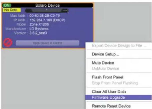
- Right-click in network view on a device block and select "Firmware Upgrade".
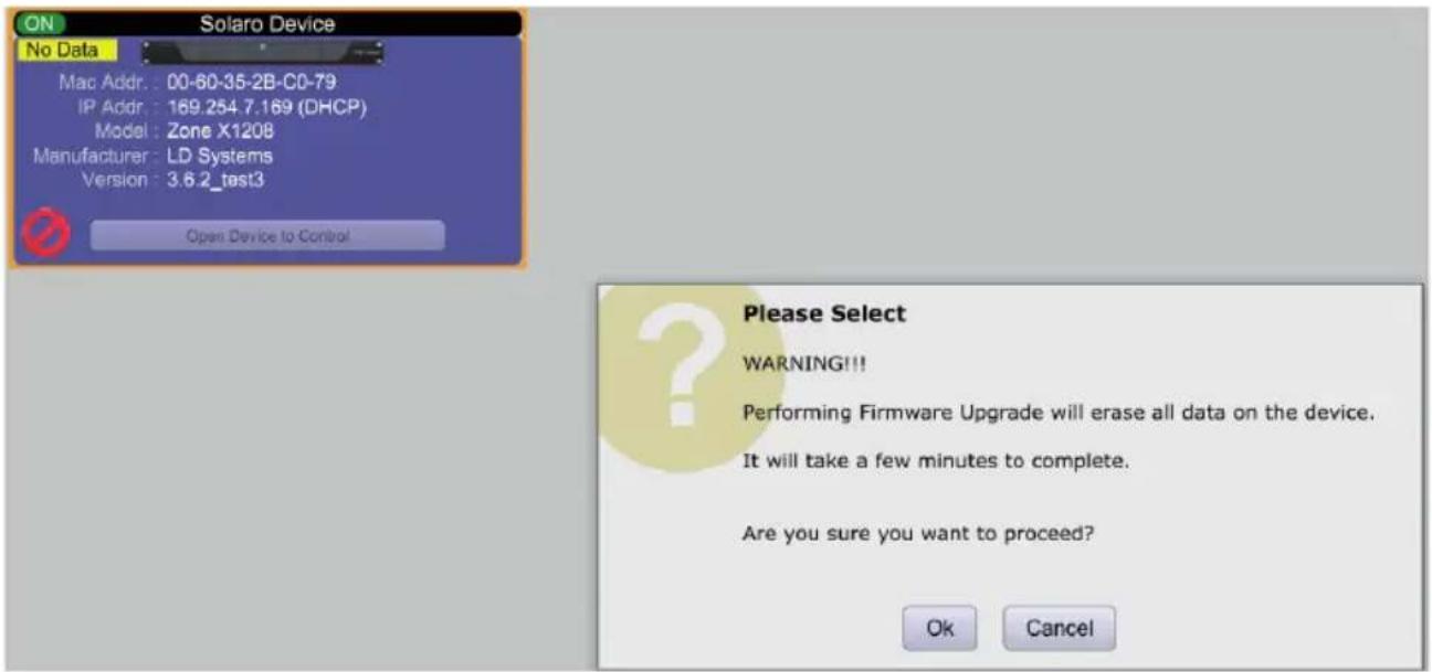
A warning then appears that the firmware upgrade will delete all data from your device. Confirm with "OK" to continue.
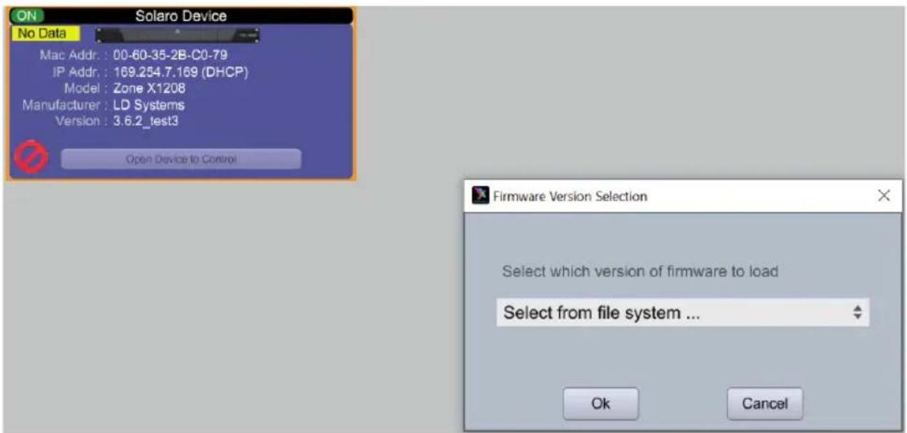
A dropdown menu now appears from which you can select the desired firmware file from a file system or a firmware version previously downloaded via the "Device Firmware Manager" (in the "Device Management" menu). Confirm with "ok" and find the folder where you saved the new firmware file. Select the file and click "Open".
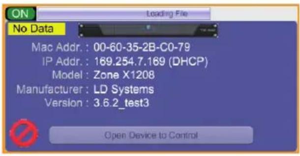
A status bar in the device window shows the progress of the firmware upgrade.
DO NOT SWITCH THE DEVICE OFF OR DISCONNECT IT FROM THE COMPUTER. If the device is switched off or disconnected from the computer during the firmware upgrade, this may result in a complete corruption of the processor. In this case, a "USB Firmware Recovery" must be performed.
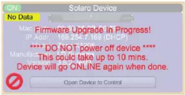
As soon as the firmware file is successfully downloaded to the device, it automatically restarts and the internal data is updated. This may take a few minutes. During this time, the network indicator is RED and the device is offline.
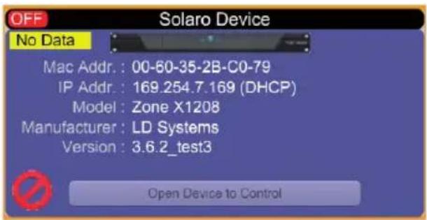
When the firmware upgrade is complete, the green "ON" indication reappears.
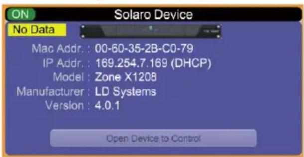
NOTE: The yellow area with the message "No Data" means that no design has been loaded to the device.
PROJECT VIEW
There are two ways to create a new project:
AUTO CONFIGURATION
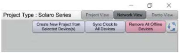
If your device is listed in network view, select it and click in the top right on Create New Project from Selected Device(s). This automatically takes you to the project view and enables you to select a design template.
EMPTY PROJECT
The second option is to create a new project via File > New Project.
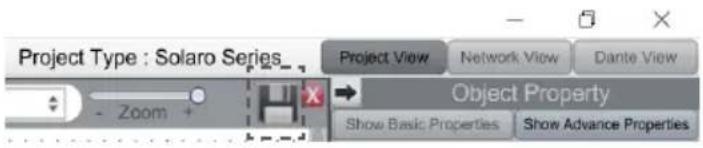
If you start with an empty project, Xilica Designer asks which DSP series you want to use. ZoneX is based on the Solaro DSP series, so choose Solaro Series.
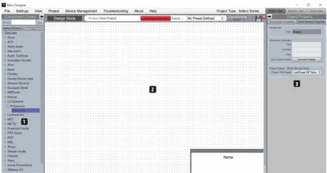
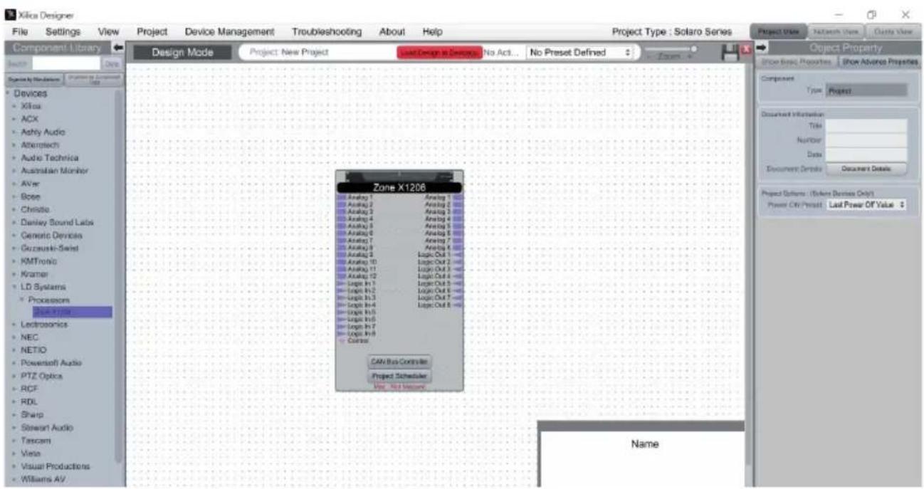
1. "COMPONENT LIBRARY" MENU
This menu provides a list of devices and design modules for use in your project. Find the ZoneX processor in LD Systems > Processors.
2.WORK AREA
The work area is used to create and configure devices.
3. "OBJECT PROPERTY" MENU
This menu lets you configure the object features for the corresponding design.
DESIGN
For demonstration purposes, in this case only one DSP hardware block will be used, however a design can also include several DSP hardware objects. A project design can be created offline (without connected hardware) and loaded on your device later.
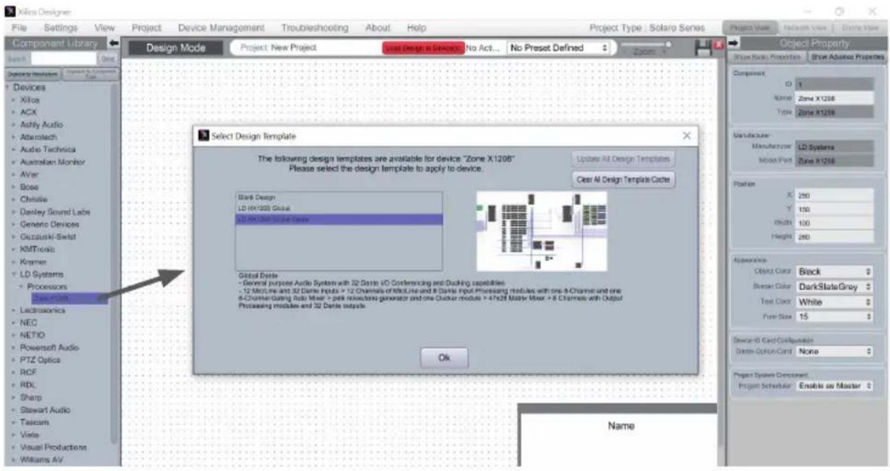
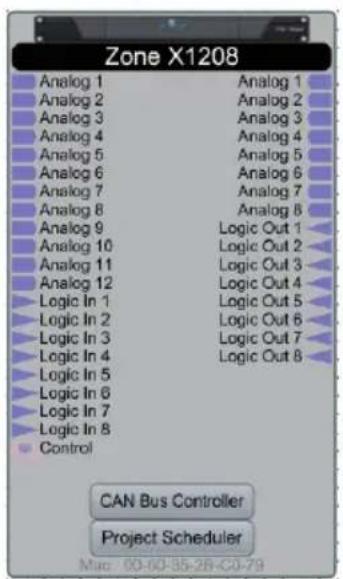
- Drag and drop the desired DSP module, Zonex1208 in this case, from the "Component Library" into the work area.
-
A selection window appears with all design templates (Select Design Template). Select one of the templates offered and you'll see a brief description and overview of its key features. Select a suitable template for your project, and confirm with ok. Detailed descriptions of the different templates can be found in the FAQ on LD Systems ZoneX.
-
The ZoneX processor is configured accordingly.
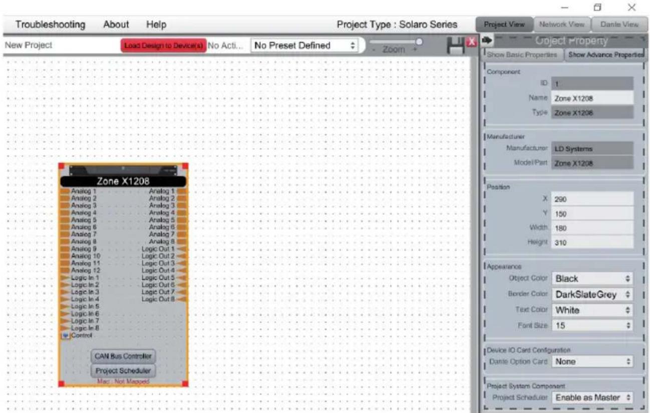
- Select the ZoneX module to highlight it. You can now adjust the device features in the "Object Property" menu on the right. Note: The object features depend on the device and vary depending on the selected object.
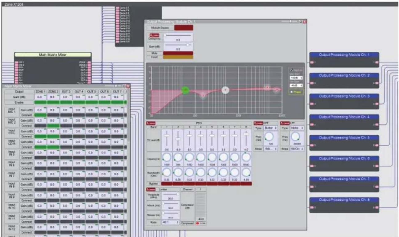
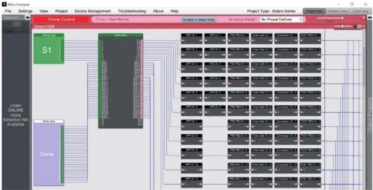
- Double-click on the Zonex module to open the schematic design overview. The "Global Dante" template is selected in this example. The window size can be changed by dragging on the corner of the window.
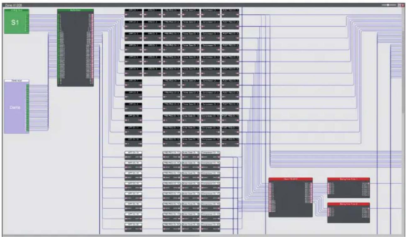
- All DSP modules can be processed offline. Double-click on the desire module to open it. You can then adjust the settings for the DSP module to your project's requirements.
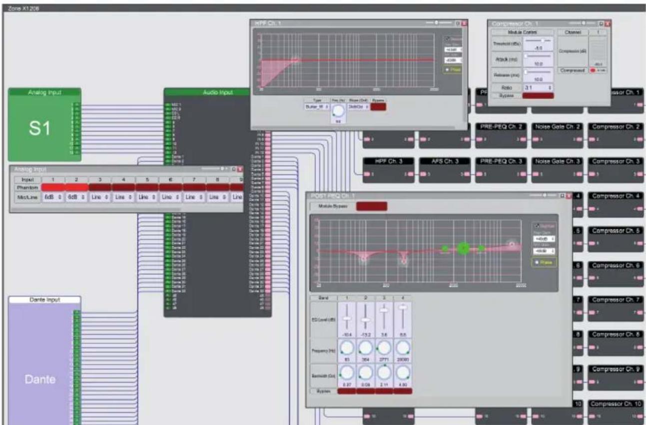
In this example, the phantom power has been activated and the gain values adjusted in the first two channels of the input settings. In addition, we have renamed the first four channels in the audio input modules and processed input channel 1.
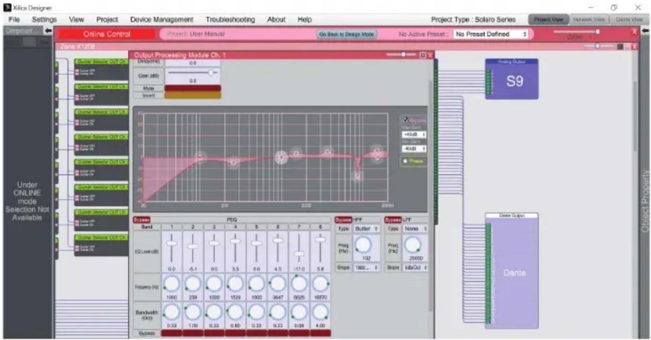
- Now double-click on the main matrix mixer module to route the input signals to the corresponding outputs. These can also be processed with an output processing module.
- If you have changed the settings offline, save your project in the desired location by clicking on File > Save As. If you have changed an existing project file, save this using File > Save. You get the same effect by clicking on the "Save" symbol in the top right of the work area.
It is a good idea to save backups of project files externally.
The file extension (naming extension) for saved project files is .pjxml.
ONLINE MODE
If you select online mode, the design file is loaded on the connected device(s) and you can make changes in real time.
In this case, all devices must be connected and online (green "ON" indicator in network view).
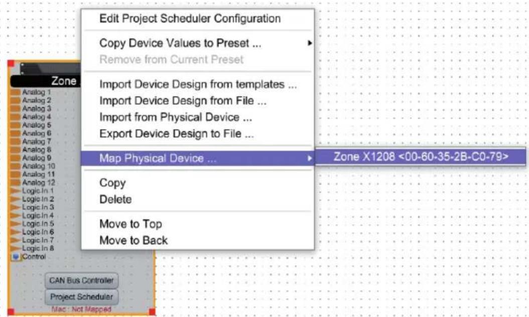
To switch to online mode, the device module must be assigned to the physical hardware.
- Select the device module you want to assign from the project view.
- Right-click on the device module and select Map to Physical Device.
- The recognised devices are now listed with their Mac addresses. If several identical devices are connected to the network, they can be identified by their Mac addresses. Network view shows the Mac addresses for the individual devices.
It is very important that the name of the device block in the design file precisely matches the unit in the network view, otherwise the design cannot be loaded on the corresponding hardware.
If everything is mapped, the color of the module changes to solid green and the Mac address of the device is shown under device module.
- Now click Load Design to Device(s), at the top of the work area.
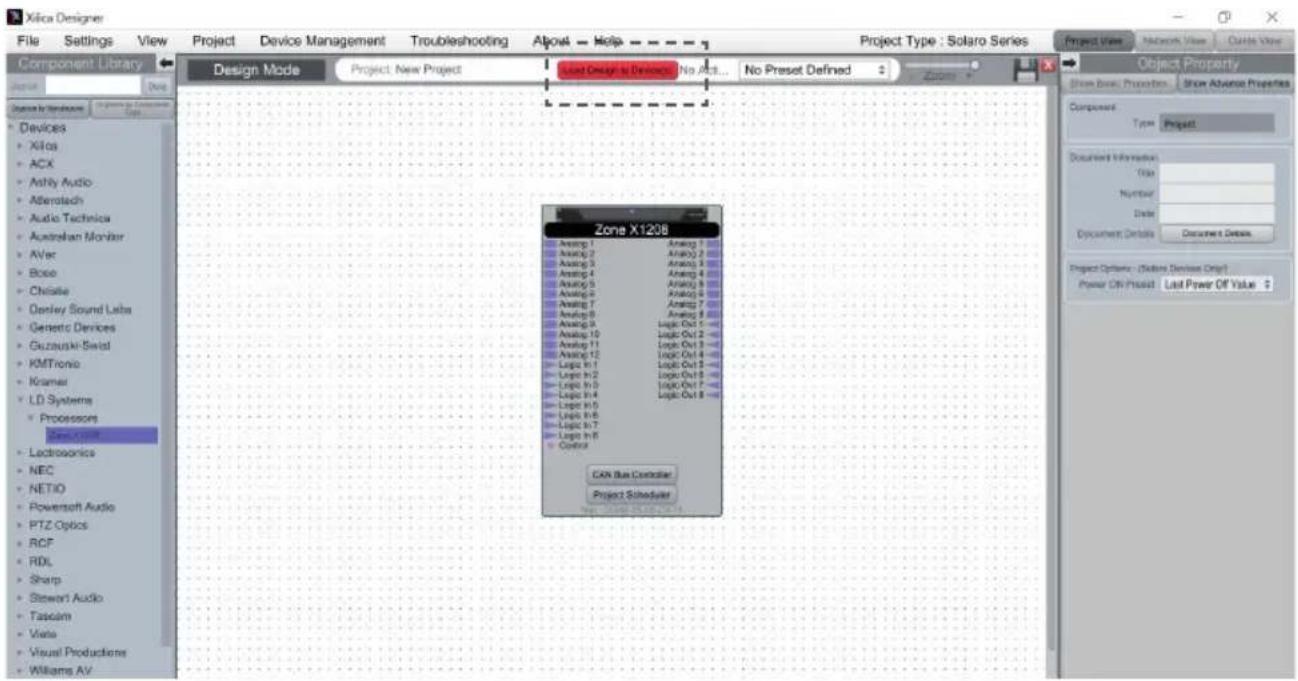
- A window appears in which you can check the devices onto which you want to load your design. Confirm with Ok.
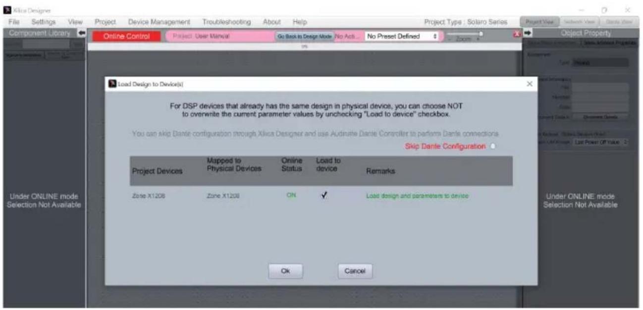
Switching to online mode may take a few minutes. Do not interrupt the process! The process progress is shown in percent in a status bar at the top of the window.
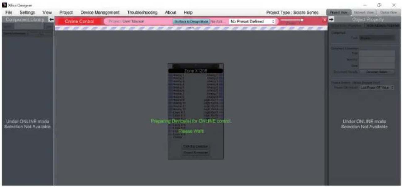
As soon as the work area appears in a solid green, you are in online mode and the design menu is no longer available.
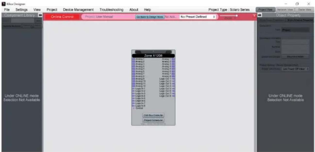
- If you want to change the settings in real time, you can either double-click on the DSP module in project view or on the device block in project view and you will then see the schematic representation of the corresponding device.
- Double-click on the desired DSP module or a I/O block to change settings in real time.
You can return to design mode at any time via the button Go Back to Design Mode at the top of the work area.
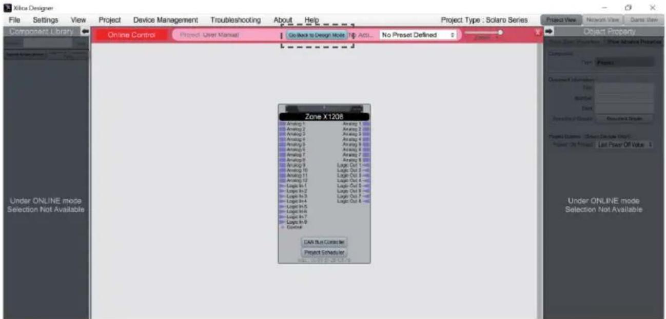
You will be asked if you want to copy the changes made online into the project design.
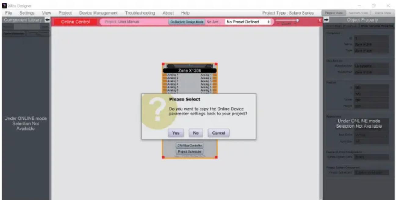
Confirm with Yes to save the online settings to the project.
Click No to return to the previous design file.
After transferring online settings to a project, the option File > Save overwrites the original project file.
Select File > Save As to create and save a new project file.
It is a good idea to save backup copies of project files externally.
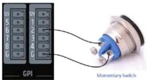
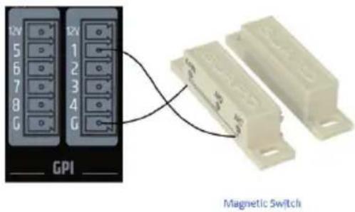
GPI/O - CONNECTION EXAMPLES
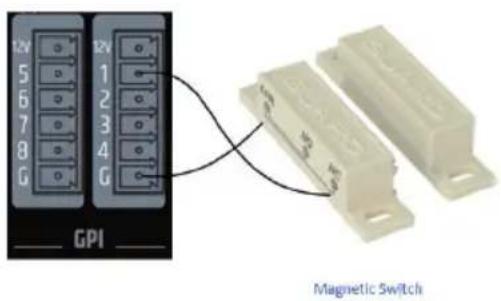
8 LOGIC INPUTS (BINARY INPUTS, GPI)
Activation via ground connection (G)

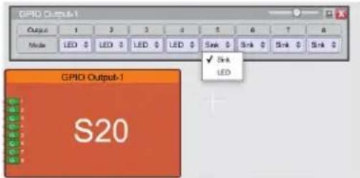
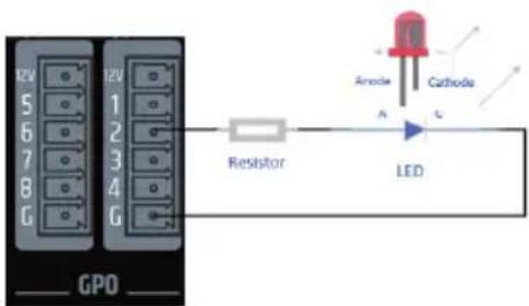
8 LOGIC OUTPUTS (BINARY OUTPUTS, GPO)
2outout modes available:
LED (3 mA)
- Sink to Ground (300 mA)
Connection example:
Each GPI offers two switching states (via software)
- This means two different presets can be driven Open and close the contacts
TECHNICAL DATA
| Item number LDZONEX1208 / 0 | |
| Product type DSP audio matrix for fixed installation | |
| General data | |
| Audio inputs 12 balanced mic/line inputs + 1 remote bus audio input | |
| Audio outputs 8 balanced line outputs | |
| Logic inputs 8 GPI - activation via ground connection. | |
| Logic outputs 8 GPO - modes: LED (3 mA) or sink (300 mA), per output selectable | |
| Remote bus Yes | |
| Connectors Inputs/outputs: 3-pole terminal block, pitch 3.81 mm; micro USB B service connector, remote IN RJ45, Ethernet RJ45 Zone1208D: Dante Primary and Secondary RJ45 | |
| LEDS Front: "POWER", "NETWORK", "REMOTE", inputs 1 - 12 and outputs 1 - 8: White signal LED, red clip LED | |
| Front panel controls No | |
| Rear panel controls Mains ON/OFF, "IP RESET" | |
| Expansion slots for Ethernet (ZONEX1208) or Ethernet + Dante (ZONEX1208D) cards | |
| Cooling Passive convection cooling | |
| Power supply Wide-range switch mode power supply | |
| Power supply connector 3-pole power supply socket (IEC) | |
| Operating voltage 90 - 240 V AC; 50/60 Hz | |
| Mains fuse T2.5 A L / 250 V | |
| Mains OFF-ON inrush current 21 A | |
| Power consumption, idle mode | 23 W |
| Max. Power consumption | 60 W |
| Operating temperature | 0 °C ... +40 °C (max. 60 percent relative humidity) |
| Width | 19" rack (483 mm) |
| Height | 1 HE (44.5 mm) |
| Depth | 315 mm (with terminal blocks) |
| Weight | 3.8 kg |
| Rack distance to the next device (height) | 1 HE |
| Rack depth (required) | 350 mm |
| Performance specifications | |
| Nominal input sensitivity | -22 dBu (sine wave, 1 kHz, max. gain) |
| Nominal input clipping | +20 dBu (Sine wave, 1 kHz) |
| Harmonic distortion (THD+N) | <0.003 percent (Line IN - OUT, +13 dBu signal, 20 Hz - 20 kHz, gain 0 dB) |
| Intermodulation distortion (IMD), SMPTE: | <0.01 percent (-10 dB under clip), analyzer bandwidth 90 kHz |
| Frequency response | 15 Hz - 22 kHz (+/-0.15 dB) |
| Input impedance | Line: 4 kohm (balanced) |
| Item number LDZONEX1208 /D |
| Signal-to-noise ratio >117 dB @ +20 dBu, gain 0 dB, 20 kHz bandwidth, A-weighted |
| Dynamic range (AES17) 112 dB |
| Channel crosstalk 120 dB @ 100 Hz, 120 dB @ 1 kHz, 105 dB @ 10 kHz |
| Common mode rejection, >60 dB (1 kHz) CMRR IEC |
| Max. Gain 42 dB |
| Digital specifications |
| DSP 40-bit floating point processing, Analog Devices dual core SHARC+ processor |
| System latency 4.3 ms |
| Resolution AD/DA converter 32 Bit |
| Sampling rate AD/DA converter 48 kHz |
| Remote bus specifications, measured between REM In and REM Out |
| Nominal input sensitivity 20 dBu |
| Nominal input clipping 20 dBu |
| Harmonic distortion (THD+N) <0.006% (+18 dBu, 20 Hz - 20 kHz) |
| Frequency response 20 Hz - 20 kHz (0.1 dB) |
| Input impedance 50 kohm (balanced) |
| Signal-to-noise ratio >105 dB (+20 dBu, 20 kHz bandwidth, A-weighted) |
| Common mode rejection, >65 dB @ 1 kHz CMRR IEC |
| Gain 0 dB |
| Phantom power +48 V DC / 500 mA |
| Protection Resettable fuse (internal) |
MANUFACTURER'S DECLARATIONS
MANUFACTURER'S WARRANTY & LIMITATIONS OF LIABILITY
You can find our current warranty conditions and limitations of liability at: https://cdn-shop.adamhall.com/media/pdf/MANUFACTURERS-DECLARATIONS_LD_SYSTEMS.pdf To request warranty service for a product, please contact Adam Hall GmbH, Adam-Hall-Str. 1, 61267 Neu Anspach / Email: Info@adamhall.com / +49 (0)6081 / 9419-0.

CORRECT DISPOSAL OF THIS PRODUCT
(valid in the European Union and other European countries with a differentiated waste collection system)
This symbol on the product, or on its documents indicates that the device may not be treated as household waste. This is to avoid environmental damage or personal injury due to uncontrolled waste disposal. Please dispose of this product separately from other waste and have it recycled to promote sustainable economic activity. Household users should contact either the retailer where they purchased this product, or their local government office, for details on where and how they can recycle this item in an environmentally friendly manner. Business users should contact their supplier and check the terms and conditions of the purchase contract. This product should not be mixed with other commercial waste for disposal.
FCC STATEMENT
- This device complies with Part 15 of the FCC Rules. Operation is subject to the following two conditions:
(1) This device may not cause harmful interference, and
(2) This device must accept any interference received, including interference that may cause undesired operation.
2. any changes or modifications not expressly approved by the party responsible for compliance could void the user's authority to operate the equipment.
NOTE: This equipment has been tested and found to comply with the limits for a Class B digital device, pursuant to Part 15 of the FCC Rules. These limits are designed to provide reasonable protection against harmful interference in a residential installation.
This equipment generates uses and can radiate radio frequency energy and, if not installed and used in accordance with the instructions, may cause harmful interference to radio communications. However, there is no guarantee that interference will not occur in a particular installation. If this equipment does cause harmful interference to radio or television reception, which can be determined by turning the equipment off and on, the user is encouraged to try to correct the interference by one or more of the following measures:
Reorient or relocate the receiving antenna.
Increase the separation between the equipment and receiver.
Connect the equipment into an outlet on a circuit different from that to which the receiver is connected.
Consult the dealer or an experienced radio/TV technician for help.
FCC RADIATION EXPOSURE STATEMENT
This equipment complies with FCC radiation exposure limits set forth for an uncontrolled environment. This equipment should be installed and operated with minimum distance 20cm between the radiator 6 your body
CE COMPLIANCE
Adam Hall GmbH states that this product meets the following guidelines (where applicable):
R&TTE (1999/5/EC) or RED (2014/53/EU) from June 2017
Low voltage directive (2014/35/EU)
EMV directive (2014/30/EU)
ROHS (2011/65/EU)
The complete declaration of conformity can be found at www.adamhall.com.
Furthermore, you may also direct your enquiry to info@adamhall.com.
EU DECLARATION OF CONFORMITY
Hereby, Adam Hall GmbH declares that this radio equipment type is in compliance with Directive 2014/53/EU.
The full text of the EU declaration of conformity is available at the following
internet address: www.adamhall.com/compliance/
Printing errors and mistakes, as well as technical or other changes are reserved!
DEUTSCH
2 INPUT 6 OUTPUT LEDs
Consummation max. 42 dB
(Valid in the European Union and other European countries with waste separation)
WARUNKI WSTEPNE FUNKCJONOWANIA
8 WEJSC LOGICZNYCH (WEJSCIA BINARNE, GPI)
Sterowanie masa (G)
8 WYJSc LOGICZNYCH (WYJSCIA BINARNE, GPO)
DEKLARACJA ZGODNOSCI WE
2 LED INGRESS O USCITA
8 INGRESSI LOGICI (INGRESSI BINARI, GPI)
- DEUTSCH
- SAFETY INFORMATION
- FOR EQUIPMENT THAT Connects TO THE POWER MAINS
- CAUTION! HIGH VOLUMES IN AUDIO PRODUCTS!
- FEATURES
- PACKAGING CONTENT
- CONNECTIONS, CONTROLS AND DISPLAY ELEMENTS
- GLOBAL STATUS LEDs
- INPUT 6 OUTPUT LEDs
- POWER CONNECTOR AND FUSE HOLDER
- ON/OFF SWITCH
- ETHERNET-USB-RESET
- REMOTE
- GPO
- 8GPI
- OUTPUTS
- INPUTS
- CONNECTING DEVICES
- PREREQUISITES FOR OPERATION
- A NETWORK CONNECTION BETWEEN HOST COMPUTER AND ZONEX PROCESSOR CAN BE CREATED AS FOLLOWS:
- ROUTER WITH ACTIVATED DHCP SERVER (RECOMMENDED)
- NON-DHCP-BASED DIRECT CONNECTION OR INDIRECT CONNECTION VIA ETHERNET SWITCH
- XILICA DESIGNER SOFTWARE
- MAC OS X INSTALLATION
- WINDOWS INSTALLATION
- STARTING THE SOFTWARE
- NETWORK VIEW
- FIRMWARE UPGRADE
- FIRMWARE UPGRADE PROCEDURE
- PROJECT VIEW
- AUTO CONFIGURATION
- EMPTY PROJECT
- "COMPONENT LIBRARY" MENU
- 2.WORK AREA
- "OBJECT PROPERTY" MENU
- DESIGN
- ONLINE MODE
- GPI/O - CONNECTION EXAMPLES
- LOGIC INPUTS (BINARY INPUTS, GPI)
- LOGIC OUTPUTS (BINARY OUTPUTS, GPO)
- TECHNICAL DATA
- MANUFACTURER'S DECLARATIONS
- MANUFACTURER'S WARRANTY & LIMITATIONS OF LIABILITY
- CORRECT DISPOSAL OF THIS PRODUCT
- FCC STATEMENT
- FCC RADIATION EXPOSURE STATEMENT
- CE COMPLIANCE
- EU DECLARATION OF CONFORMITY
- WARUNKI WSTEPNE FUNKCJONOWANIA
- WYJSc LOGICZNYCH (WYJSCIA BINARNE, GPO)
- DEKLARACJA ZGODNOSCI WE
- LED INGRESS O USCITA
Brand : LD Systems
Model : ZONE X 1208
Category : Processor