16256 - Dashcam Eufab - Free user manual and instructions
Find the device manual for free 16256 Eufab in PDF.
User questions about 16256 Eufab
0 question about this device. Answer the ones you know or ask your own.
Ask a new question about this device
Download the instructions for your Dashcam in PDF format for free! Find your manual 16256 - Eufab and take your electronic device back in hand. On this page are published all the documents necessary for the use of your device. 16256 by Eufab.
USER MANUAL 16256 Eufab
natural_image
Black-and-white photo of a remote control device with a monitor and wrist strap (no text or symbols visible)EAL GmbH
SELV (Safety Extra Low Voltage)
natural_image
Pure diagram of curved lines with a numbered label (4) and number 1, no text or symbols present.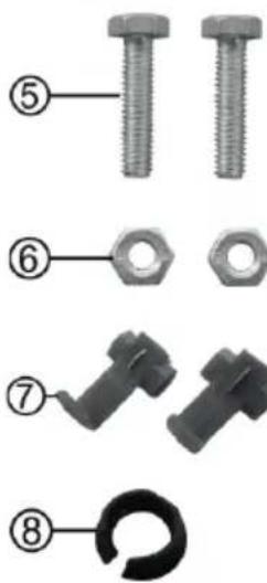
text_image
Diagram showing eight labeled parts of a bolt and nut assembly, including threaded and threaded fasteners with numbered callouts.text_image
Diagram showing three types of electronic devices with numbered labels: a connector, a cable, and a plug.6.2 Montage

natural_image
3D model of a camera assembly with labeled component (Bild 2: Montage Kamera), no other text or symbols visible.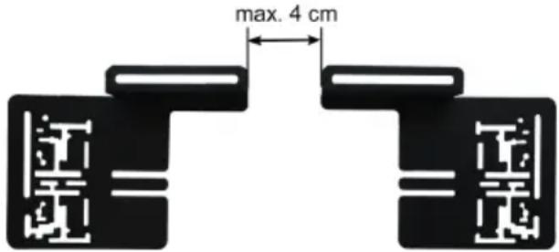
text_image
max. 4 cmnatural_image
Close-up of a black plastic component with a curved arrow indicating rotation (no text or symbols)
natural_image
Close-up of a black plastic mechanical component with a circular base and handle (no visible text or symbols)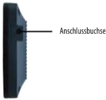
GB Cordless rear view camera system, 4.3 display
Item no. 16256
Contents
- Proper use of the product 9
- Scope of delivery 9
- Specifications 10
- Safety precautions 10
- Symbol explanation 10
- Operating instructions 11
6.1 Overview 11
6.2 Installation 11
6.2.1 Checking the installation location for suitability 11
6.2.2 Removing the rear number plate: ____ 11
6.2.3 Pass through for the camber cable 11
6.2.4 Mounting the camera 12
6.2.5 Connecting the camera 12
6.2.6 Mounting the monitor 13
6.2.7 Functionality test 13
6.3 Monitor settings 13
6.4 Replacing the fuse 14
6.5 Troubleshooting 14 - Maintenance and Care, Storage 14
- Notes regarding environmental protection 14
- Contact information 15

WARNING
Please read the operating instructions carefully prior to use and observe all safety instructions! Non-compliance can lead to personal injuries, damage to the device or your property!
Store the original packaging, the receipt and these instructions so that they may be consulted at a later date! When passing on the product, please include these operating instructions as well.
Please check the contents of the package for integrity and completeness prior to use!
1. Proper use of the product
The rear view camera system is intended exclusively for improving the visibility during brief reverse driving and parking with a vehicle.
The rear view camera system does not release you from the due diligence of looking around and carefully proceeding when driving in reverse.
This device is not designed to be used by children or persons with limited mental abilities or without experience and/or lack of required specialist knowledge. Keep children away from the device.
The device is not designated for commercial use.
Use according to the intended purpose also includes the observance of all information in these operating instructions, particularly the observance of the safety notes. Any other utilisation is considered to be contrary to the intended purpose and may lead to material damage or personal injuries. EAL GmbH assumes no liability for damage resulting from improper use.
2. Scope of delivery
- Monitor
- Transmitter
- Monitor holder
- Camera
- 12 V vehicle connection
- Mounting material
3. Specifications
Monitor:
Size / resolution: 4.3", 10.9 cm / 480 x 271 pixels
Dimensions: 123 x 77 x 21 [mm]
Technology: LCD colour display
Operating voltage: 12 V DC
Camera:
Resolution: 640 x 480 pixels
Colour sensor: CMOS
Viewing angle: 110°
Night vision function: 6 IR LEDs (switch on automatically at night)
Operating voltage: 12 V DC
Transmitter:
Transmitting frequency: 2.4 GHz
Range: approx. 10 m
Operating voltage: 12 V DC
Temperature range: - 10 °C to + 50 °C
4. Safety precautions

- The warning triangle indicates all instructions which are important for safety. Always follow these otherwise you could injure yourself or damage the device.
• Children may not play with the device. - Cleaning and user maintenance may not be carried out by children without supervision.
- Do not treat packaging material carelessly. This may become a dangerous plaything for a child!
- Only use this product for its designated purpose!
- Do not manipulate or disassemble the device!
- For your own safety, only use accessories and spare parts that are stated in these instructions or that are recommended by the manufacturer!
- If you are unsure with the installation, operation or function of the rear view camera system, ask for advise from qualified technical personnel.
- Do not put the rear view camera system in operation if there is damage or malfunctions on the device or on the cables.
- Ensure good ventilation for the monitor and transmitter, never cover these components with covers or other objects.
- Do not lengthen the cables. Do not use any cable other than the supplied cable or other accessories.
- To disconnect the power supply, always pull on the plug itself, never on the cable.
- Protect the monitor from penetration of liquids. Position the monitor in the vehicle so that it is protected from condensation. Never operate the device with damp or wet hands.
- With extreme temperatures or quick fluctuations in temperature the system could possibly not function properly.
- The monitor screen can appear overexposed when there is strong sunlight directly on the camera lens.
5. Symbol explanation

Complies with EC directives
Lackenzeichanitel products may not be disposed of in the household waste

Read the operating instructions

SELV (Safety Extra Low Voltage) (Protection class III)

ECE test mark
6. Operating instructions
6.1 Overview
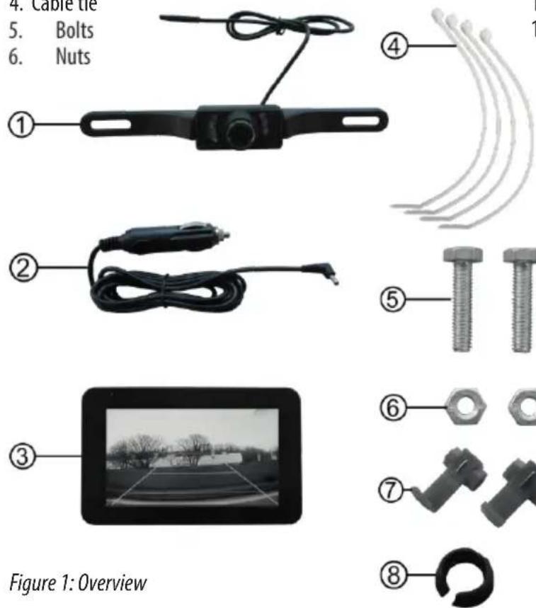
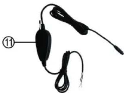
- Camera with IR LEDs and connection cable
- Monitor connection cable for 12 V vehicle socket
- Monitor
- Cable tie
- Bolts
-
Nuts
-
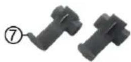
Clamp connectors
-
Gasket
-
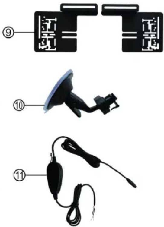
Camera holder
-
Monitor holder
-
Transmitter with connection cable
text_image
4. Cable tie 5. Bolts 6. Nuts ① ② ③ ④ ⑤ ⑥ ⑦ ⑧ Figure 1: Overview
text_image
Diagram showing three types of electronic devices with numbered labels: a connector, a connector plug, and a cable.6.2 Installation

These instructions are only valid as an example due to the various vehicle types and cannot be directly used for every vehicle.
6.2.1 Checking the installation location for suitability
Before you start with the installation, check whether the location chosen is suitable for installation of the rear view camera. Therefore hold both camera holders (item 9 in the overview), as precisely as possible over the rear license plate. The number plate and the number plate lighting must not be covered by the camera. The camera and the holder must not block the boot during closing. The camera can be mounted over or under the number plate. The camera must be mounted so that the cable connection is located above.
6.2.2 Removing the rear number plate
First remove the rear number plate and, if present, also the number plate holder of your vehicle.
6.2.3 Pass through for the camber cable
If there is no opening behind the number plate that can be used for passing through the camera cable, you must drill a 10 mm diameter hole to lay the cable in the interior. In this case first remove the interior lining of the boot.

Check whether there are cables, wires or other components located at the position selected, which could be damaged by the drilling.
When the hole for the cable to pass through has been drilled, protect the bare areas of the sheet metal with rust protection paint or other suitable paint.
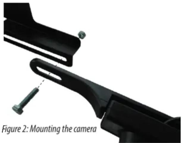
6.2.4 Mounting the camera
Connect the camera to the camera holders, item 9 in the overview, refer to Figure 2. For this use the bolts, item 5 in the overview and the nuts, item 6 in the overview. Do not tighten the bolts yet. Place the number plate or the number plate holder on the camera holders. Align the camera holders so that the fastening holes of the number plate or the number plate holder can be used. During this both number plate holders must be no further apart than 4 cm, Figure 3.
Now tighten the bolts.
The gasket, item 8 in the overview, has a collar on one side. This collar must later lie on the outside of the vehicle metal. Now insert the camera cable through the gasket from the collar side. Now insert the camera cable with the gasket through the hole behind the number plate. Set the number plate or the number plate carrier on the camera holders and mount this combination back on your vehicle.
natural_image
3D mechanical assembly diagram showing a camera mounting mechanism with no visible text or symbols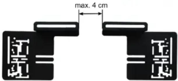
text_image
max. 4 cmFigure 3: Camera holders spacing
6.2.5 Connecting the camera
Select a suitable installation location for the transmitter, item 11 in the overview. Here it is possibly necessary to remove parts of the lining in the boot or in the passenger compartment of the vehicle. The installation location must not be too far removed from the camera and the rear light, pay attention to the cable lengths. In addition the transmitter must be placed as close as possible to the receiver (monitor), without metallic components, body metal, ribs and reinforcements being able to negatively influence the radio transmission. Fasten the transmitter, e.g. with cable ties. Lay the cable so that it cannot be bent, pinched or stretched.

Caution: For the next step, working on the electrical system of the vehicle, it is necessary to unclamp the battery. This could cause, for example, the radio code, data of the on-board computer or other settings to be lost. To do this, read the user's manual of your vehicle or ask the vehicle manufacturer.
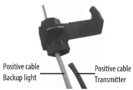
Disconnect the battery. Look for the positive and negative cable for the backup light. Connect the red positive cable of the transmitter with the aid of the clamp connector. Item 7 in the overview, with the positive cable of the backup light. Connect the black negative cable of the transmitter to the negative cable of the backup light. Proceed as shown in Figures 4 to 6.
text_image
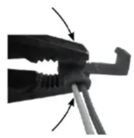
Positive cable Backup light Positive cable TransmitterFigure 4: Inserting the cable Figure 5: Pressing in the small contact plates
natural_image
Close-up of a mechanical clamp or tool with arrows indicating motion direction (no text or symbols visible)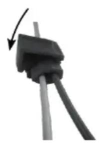
natural_image
Close-up of a black electrical plug with a curved arrow indicating rotation (no text or symbols)Figure 6: Closing the safety clamp

If you are unsure during the electrical installation, ask a specialist workshop for advice. There is a risk of personal injury and property damage.
6.2.6 Mounting the monitor
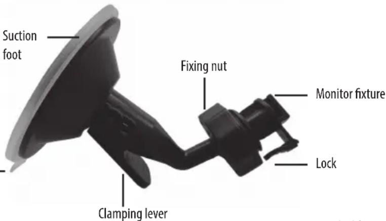
Insert the monitor fixture of the monitor holder, position 10 in the overview, see Figure 7, in the recess on the back of the monitor. Slide the monitor completely on the fixture, until the lock engages. Insert the angle plug of the monitor connection cable, item 2 in the overview, in the connection socket of the monitor, Figure 8.
Tab
text_image
Suction foot Fixing nut Monitor fixture Lock Clamping leverFigure 7: Monitor holder
Fasten the monitor with the holder on the windscreen of your vehicle, as shown in Figures 9 and 10.
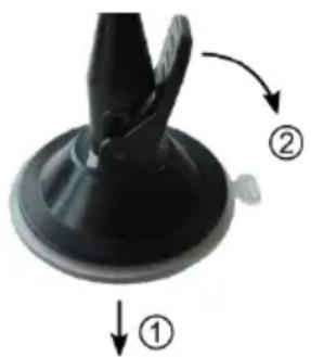
natural_image
Close-up of a black plastic mechanical component with labeled parts (① and ②), no text or symbols present.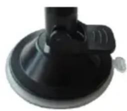
natural_image
Close-up of a black plastic mechanical component with a handle and base (no visible text or symbols)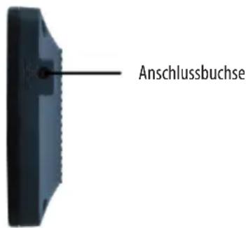
6.2.7 Functionality test
Plug the camera cable and the cable of the transmitter together. Switch on the ignition of your vehicle. Insert the plug of the monitor cable into the 12V socket of your vehicle. If the installation has been correctly done, a blue indicator light in the left top of the frame of the monitor lights up. Now engage reverse gear. If the transmitter and camera are connected correctly the monitor displays an image. If no image can be seen, proceed according to the fault table in Section 6.5 and correct the fault.
If you have not detected any fault, turn off the ignition and disconnect the plug of the monitor cable. Lay and fasten the cable. Replace all the lining parts in the boot and in the passenger compartment.
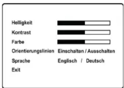
6.3 Monitor settings
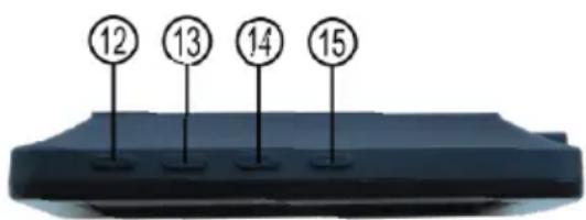
There are four buttons on the top of the monitor. Figure 11.
12 ON/OFF button
13 + button
14 Menu button
15 - button
To turn the monitor on and off press button 12. The screen menu is activated by pressing the menu button 14. Continuing to press the menu button further switches from menu point to menu point. The settings for each menu point can be made with the + and - buttons.
To leave the screen menu, select „EXIT“ by continuing to press the menu key and then press the + or - button.
text_image
12 13 14 15Figure 11: Monitor operation
Turn the knurled screw at the tip of the 12 V connector of the monitor cable anti-clockwise until it is released from the connector and it can be removed. The fuse is exposed and can be removed from the connector. Replace the fuse with another of the same strength and screw the knurled screw back into the connector.
Fuse: 6.0 x 30 mm, F, 1 A, 250 V
6.5 Troubleshooting
| The ignition of the vehicle and the monitor are turned on, reverse gear is engaged, but the display remains dark. The blue indicator light is not lit up | The plug of the monitor cable is not plugged into the 12 V vehicle socket. | Insert the plug of the monitor cable into the 12 V vehicle socket |
| The fuse in the plug of the monitor cable triggered and must be replaced | Replace the fuse in the plug of the monitor cable | |
| The fuse for the 12 V vehicle socket triggered and must be replaced. | Replace the fuse in the fuse box of the vehicle | |
| The ignition of the vehicle and the monitor are turned on, reverse gear is engaged, the blue indicator light is lit up but the display does not show an image. | No radio connection could be made between the camera and the monitor. The cable of the camera and the transmitter are not correctly connected or they came apart. | Check the correct connection of the cable to the camera, transmitter and backup light. |
| The image on the monitor malfunctions. | The signal between the camera and the monitor has interference from other radio sources (e.g. cellphone, transmitter for garage door opener). | Switch off the radio transmission sources or get away from these radio sources. |
| The radio connection between the camera and monitor is not strong enough to transmit the signals without interference. | Change the position of the transmitter so that the distance to the monitor is smaller and no metallic obstacles negatively influence the transmission. | |
| The monitor does not display a clear image. | The camera lens is dirty. Carefully clean the lens. | |
| Strong light is falling directly on the lens of the camera. | As soon as the strong incidence of light is gone, the image quality is again ok. |
7. Maintenance and Care, Storage
Before cleaning unplug the connection cable from the monitor. Clean the housing of the monitor with a soft, dry cloth. Do not use any abrasive or solvent-based cleaning agents. Never allow liquids to ingress into the housing.
When not in use store the rear view camera system in a dry location. Do not expose the camera system to any strong temperature fluctuations. The resulting condensation can damage the system.
8. Notes regarding environmental protection
Do not dispose of electrical devices with the household waste! Electrical and electronic scrap must be collected separately and disposed of in an environmentally responsible manner for recycling. Please contact your community or city administration regarding disposal options for electrical and electronic scrap.
9. Contact information
EAL GmbH
natural_image
Pure diagram of curved lines with a numbered label (4) and number 1, no text or symbols present.natural_image
Pure electrical circuit lines without any symbols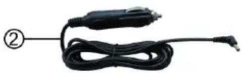
natural_image
Coiled black automotive electrical plug with terminal connector, labeled with number ② (no text or symbols on the plug itself)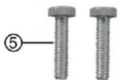
natural_image
Close-up of two metallic hexagonal bolts with a numbered label (5) pointing to one bolt (no text or symbols on the bolts themselves)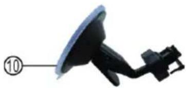
natural_image
Close-up of a black satellite dish antenna with attached cable (no text or symbols visible)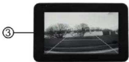
natural_image
Black-and-white photo of a rural road with trees and buildings, no visible text or symbols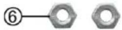
natural_image
Black electronic device with attached cable and connector, labeled with number 11 (no text or symbols on the device itself)natural_image
Close-up of a black plastic component with two curved arrows indicating motion or assembly (no text or symbols)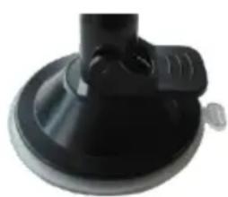
natural_image
Close-up of a black plastic mechanical component with a circular base and protruding knob (no text or symbols visible)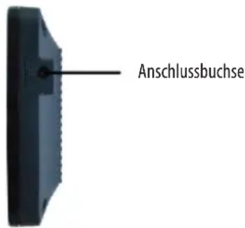
natural_image
Diagram of curved lines with a numbered label (4) pointing to one end, no text or symbols present.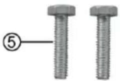
natural_image
Two metallic screw-like components with hexagonal end caps, labeled with number 5 (no text or symbols on the parts themselves)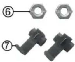
natural_image
Two mechanical components with hexagonal nuts, labeled ⑥ and ⑦ (no text or symbols on parts)
text_image
Diagram showing three types of electronic devices with numbered labels: a connector, a connector plug, and a cable.6.2 Montage

natural_image
Close-up of a mechanical clamp or tool with directional arrows indicating movement (no text or symbols visible)natural_image
Close-up of a black electrical plug with a curved arrow indicating rotation (no text or symbols)natural_image
Close-up of a black plastic mechanical component with labeled parts (① and ②), no readable text or symbols beyond labels.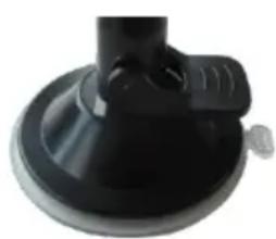
natural_image
Close-up of a black plastic mechanical component with a circular base and protruding knob (no text or symbols visible)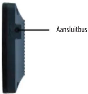
Zekering: 6,0 x 30 mm, snel, 1 A, 250 V
6.5 Foutopsporing
text_image
Diagram showing three labeled components of a device with numbered labels (⑨, ⑩, ⑪) and corresponding parts.6.2 Montaggio

natural_image
Close-up of a black plastic component with a curved handle and base, labeled with arrows ① and ② (no text or symbols on the object itself)
natural_image
Close-up of a black plastic mechanical component with a circular base and handle (no visible text or symbols)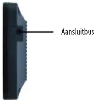
Fusibile: 6,0 x 30 mm, F, 1 A, 250 V
6.5 Ricerca errori