
OTW420B - Television LG - Free user manual and instructions
Find the device manual for free OTW420B LG in PDF.
| Product type | TV wall mount |
| Brand | LG |
| Model | OTW420B |
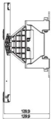
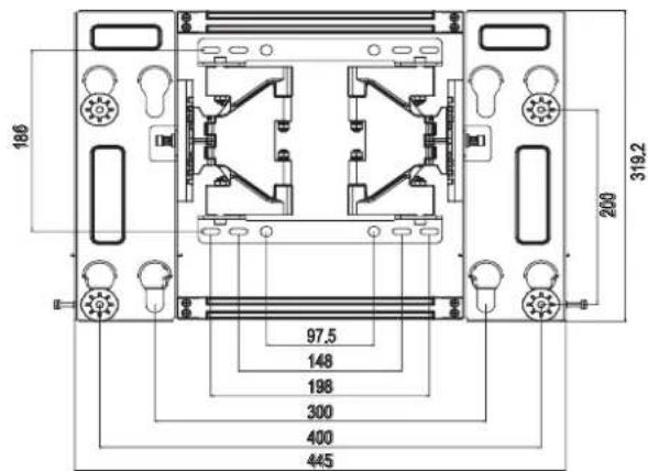
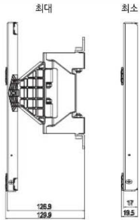
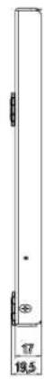
| Dimensions (W x H x D) | 445 x 319.2 x 17 mm |
| Weight | 2.7 kg |
| VESA Compatibility | 400 x 200 mm and 300 x 200 mm |
| Maximum load (tension) | 32 kg |
| Material | Steel |
| Included components | 6 anchor bolts, 6 fixing screws, 4 spacer guides A, 4 spacer guides B, 4 spacer guides C, 4 fixing screws for guides A (M6 x L35), 4 fixing screws for guides B (M6 x L18), 4 protective pads, installation manual |
| Mounting type | Wall mount, vertical only |
| Compatible wall materials | Concrete, lightweight concrete, stone, brick, hollow blocks (not plaster or MDF) |
| Adjustable tilt | Yes, via adjustment screw (tilt forward or backward) |
| Safety lock | Lower locking springs |
| Installation required | By a qualified installer (recommended) |
| Necessary tools | Drill with ∅8 mm bit (concrete), Phillips screwdriver, 8mm socket wrench, level |
Frequently Asked Questions - OTW420B LG
User questions about OTW420B LG
0 question about this device. Answer the ones you know or ask your own.
Ask a new question about this device
Download the instructions for your Television in PDF format for free! Find your manual OTW420B - LG and take your electronic device back in hand. On this page are published all the documents necessary for the use of your device. OTW420B by LG.
USER MANUAL OTW420B LG
Printing specification
| Drawn Approved | Checked | ||
| SignatureMMM/DD/YYYY | Bohyeon.yu Jongok.kimOct/14/2016 Oct/14/2016 | Mira.wooOct/14/2016 |
- Model Description
| :1 OTW420B LG MFL68484590 | :£ | Part number | : |
| :3 AL Accessory (1707-REV02) | :£ | (Revision number) |
- Printing Specification
| : 182 mm x 257 mm (B5) (W xH) | |
| 2. Printing colors | |
| : 1 Color (Black) | |
| : 1 Color (Black) | |
| 3. Stock (Paper) | |
| : Uncoated, wood-free paper 120 g/m2 | |
| : Uncoated, wood-free paper 80 g/m2 | |
| : Perfect binding | |
| : ENG/KOR/FRE/GER/ITA/JPN/POR_BR/RUS/SPA/TWN (10) | |
| : 100 | |
| NOTE | "This part contains Eco-hazardous substances (Pb, Cd, Hg, Cr6+, PBB, PBDE, etc.) within LG standard level,Details should be followed Eco-SCM management standard[LG(56)-A-2524].Especially, Part should be followed and controlled the following specification.(1) Eco-hazardous substances test report should be submitted when Part certification test and First Mass Production.(2) Especially, Don't use or contain lead(Pb) and cadmium(Cd) in ink. |
- Origin Notification
| :LGEAkintedGEKazakDERS | Printed in Korea | Printed in Mexico |
| :LGEAzintedGEBrazil:LGESY | Printed in Poland | Printed in China |
| :LGEPrintedGEEgypt:LGETH | Printed in Mexico | Printed in Thailand |
| :LGEIPrintedGENDIA :LGEVN | Printed in China | Printed in VietnamMade by LG Electronics (Only TW Suffix) |
| :LGEIPrintedGEAlonagGEWR | Printed in Russia | Printed in Poland |
| :LGEARnted in Algeria |
- Changes
| 10 | ||||
| 9 | ||||
| 8 | ||||
| 7 | ||||
| 6 | ||||
| 5 | ||||
| 4 | ||||
| 3 | ||||
| 2 | Jun/12/2017 | SunheeLee | EKLH500130 | [OTW420] 1. To add model name(55LJ54*, 55/65UJ62*)2. To arrange component's order in manual |
| 1 | NOV/23/2016 | Bohyeon.yu | EKLGB01539 | Changed the image about OLED65G7* (RMS: 5772) |
| Rev. Number | MMM/DD/YYYY | Signature | ECO Number | Change Contents |
Pagination sheet
Wall mounting bracket
Please read this manual carefully before operating your set and retain it for future reference.
OTW420B
COMPONENT
Wall mounting anchor 6 units
Wall mounting screw
6 units
Install manual

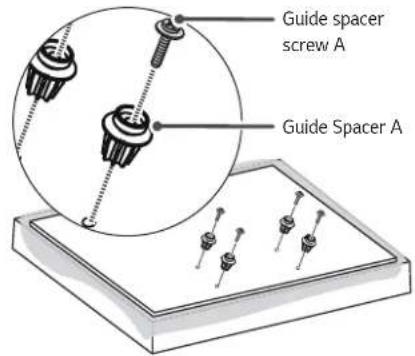
Guide spacer A 4 units

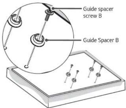
Guide spacer B 4 units

Guide spacer C 4 units
Guide spacer screw A
4 units
(M6 x L35)

Guide spacer screw B
4 units
(M6 x L18)

Set protection cushion
4 units

IMPORTANT SAFETY INSTRUCTIONS
- If you are a professional installer, please read this manual carefully before installing the product.
- If you are a professional installer, please give this manual to the user after installing the product and ensure that the user also reads the manual carefully and retains it for future reference.
After reading the manual, please keep it handy for future reference.

Warning
The product should be installed by a qualified professional specified by the retail store.
Product installation by non-qualified personnel is very dangerous and may cause personal injury.
When moving or replacing the product after installation, contact a qualified installer specified by the retail store.
Installation or movement of the product must be carried out by a skilled professional. If an unqualified person moves and installs the product, it may cause safety risks.
Be sure not to hang the power cable and signal cable on the back of TV when installing the wall-mounted TV.
Damaged cables may result in fire, electric shock, or damage to the product.
The product should be installed where its weight can be fully supported.
If the product is installed on a weak surface, the product may fall, causing injury.
Do not hang on this product, protect the product from severe impacts after the installation.
The product may fall and cause injury.

Caution
Follow the instructions in this manual to product properly.
If you do not follow these instructions, the product may be installed incorrectly and cause serious injury or the product may become damaged.
When installing the product, first check that the wall is strong enough. Use the anchors and screws provided.
If you use anchors and screws that are not specified by the manufacturer, they may not hold the weight of the product, causing safety issues.
Do not clean the product with a wet towel, and do not place a heater, or humidifier beneath it.
Moisture, steam or heat permeating into this product may result in fire, electric shock or product damage.
Make sure that the power cord is removed from the outlet before installing the product.
Otherwise, it may cause an electric shock or fire.
Be sure to use the accessory cable provided. Otherwise, friction between the product and the wall may cause damage to the connector. (Depending on model)
To install or adjust the height of the product, two or more people are needed.
If you try to install or move the product alone, it may fall and cause injury or the product may become damaged.
When drilling holes into the wall, make sure you use a drill and drill bit with the specified diameter. Ensure that you also follow the instructions regarding the depth of the holes.
Otherwise, the product may be installed incorrectly and cause safety issues.
Keep this product away from sprinklers, sensors, high-tension wires and power sources. Do not install it in a location where vibrations or impacts are likely to occur.
Wear safety gloves when installing the product. Do not use your bare hands.
Otherwise, it may cause personal injury.

BEFORE INSTALLATION
* Do not use the product for purposes other than mounting a display on the wall.
* When installing/using the wall mount, be cautious of product damage and avoid accidents.
* Install the wall mount according to the installation manual.
* If you have not fully read and understood the installation manual, do not install the product and contact the dealer to have a specialized installer install the product for you.
* Even if you are not a specialized installer, it is advantageous to have experience in mechanical or construction field in completely understanding this manual and installing the product.
* Mount the product only on a concrete wall. LG Electronics Inc. is not liable for any accidents caused by mounting the product on walls made of any other materials, including wood, plywood, and bricks.
* Install the product only on a vertical wall.
The manufacturer is not responsible for issue from installing the product on an angled wall or on the ceiling.
* Check that the accessories provided with the product are all included before installing. LG Electronics is not liable for any damage or loss of accessories after the package has been opened.
* Keep the included accessories out of reach of babies or children as it can cause safety issues including suffocation from swallowing the parts.
* Make sure screws are tight against the wall, but do not overtighten.
Applying excessive force to screws may damage to the wall, affect the product performance, or cause the product to become damaged.
* Be careful not to install a TV that exceeds the weight restrictions of the wall mount.
* Be careful with the tools used during installation to prevent accidents or damage.
Phillips head + driver (manual or motorized) / 8 mm socket wrench / Level / Drill / You may also need an ∅ 4 mm drill bit for steel or an ∅ 8 mm drill bit for concrete.

INSTALLATION
- The picture may differ from the actual product.
- Consult a professional installer prior to mounting the TV using a wall bracket.
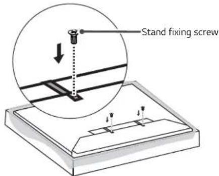
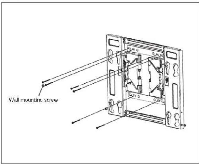
1 How to Attach the Brackets for the Product to the TV
- If the screws are not fully tightened when you fix the guide spacers, check the length of the screws again.
(Only OLED55/65C6*, OLED55/65E6*, 55/65UH95**, 55/65SJ95**, OLED55/65E7*)
(Only OLED55/65B6*, OLED55/65B7*)
(Only OLED65G6*, OLED65G7*) * Note: tighten the guide spacers after fixing the stand using the provided stand fixing screws.
1
2
(Only OLED55/65C7*) (Only 55LJ54*, 55/65UJ62*)
Work procedure
- Check to see if the display has screws installed into the mounting holes. If so, remove those.
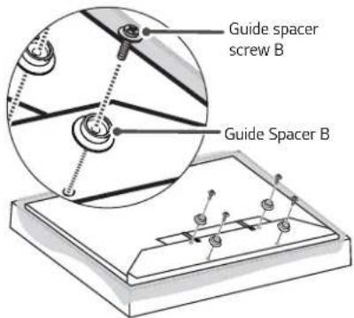
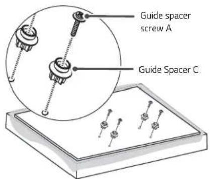
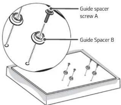
- Assemble the guide spacer and the guide spacer screw in order as shown in the picture.
- Place the TV on a table with the screen facing down. Make sure that you place it on a flat surface covered with a soft cloth or cushion to protect it from scratches.
- Secure the guide spacers to the TV with the screws. Assemble the guide spacer to the set by tightening the screw. Tighten the screw until the set, guide spacer and the screw are fully pressing against one another.
— Use the + driver (manual or motorized) when tightening the screw.
2
How to attach to masonry walls
Please follow the below direction.
— Check the material of the wall and the thickness of the finishing.
- Use the anchors for wall material of concrete, light concrete, strong natural stone, soft natural stone masonry brick and hallow block that do not crack.
- Do not mount the device on the walls made from plasterboard or medium density fiberboard (MDF). In this case, the anchor and screws must be inserted into the concrete behind the finish surface. If there is no concrete on the other side, then you must first install a separate hanger to securely install the anchors and screws.
- When installing the product on wall material not designated, install the product so that each location can withstand the pull out load of 70 kgf (686 N) and shear load of 100 kgf (980 N) or above.


natural_image
Pure mechanical component diagram without any text, numbers, or symbolsWall mounting screw

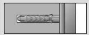

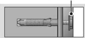

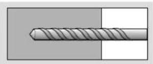
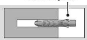
— Use the ∅ 8 mm drill bit for concrete and hammer (Impact) drill.
a. Use a drill bit ∅ 8 mm to drill a hole for the anchor location within a depth of 80 mm to 100 mm.
b. Clean the drilled hole.
c. Insert the sealed wall mounting anchor to the hole. (When inserting the anchor, use a hammer.)
d. Set the wall mount on the wall by aligning to the location of the hole. and, set the angle adjusting part to face upward.
e. Align the wall mounting screw to the hole and tighten it. Then, fasten the screws at torque of 45 kgf/cm to 60 kgf/cm.
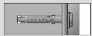
3 How to install the wall mounting bracket
→ After aligning the wall mounting bracket to the location to install, mark the part to screw on the wall and then remove the wall mounting bracket.
→ Refer to next picture to attach the wall mounting bracket.
→ Use a level to check whether the wall mounting bracket is level.
→ If the screw cannot be assembled in the designated location inevitably, it can be assembled by rearranging to the closest location. But, do not change 2 or more locations from the designated spot.
→ Assemble the wall mounting screw on 2 left and 2 right location on the top part and 1 left and 1 right location on the bottom part.
→ At this time, use a + driver (manual or motorized) or 8 mm wrench to tighten the screw so that the wall, wall mounting bracket and screw are completely pressed against one another.
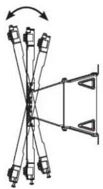
4 How to assemble the wall mounting bracket and display
- Always install the display with 2 or more people.
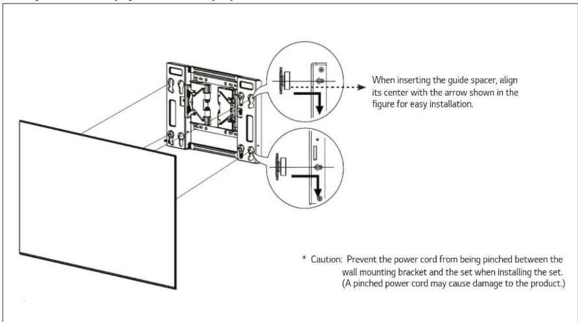
→ After attaching the guide spacers to the set, hang it on the wall mounting bracket in the direction of the arrows. Attach the lower part first, then attach the upper part by slightly lifting up the set.
— Make sure that the product is attached securely by pulling on the bottom of the set.
— When mounting the product that has a speaker, hold and lift up the product, not the speaker.
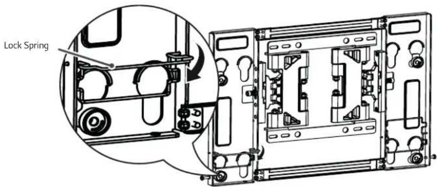
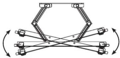
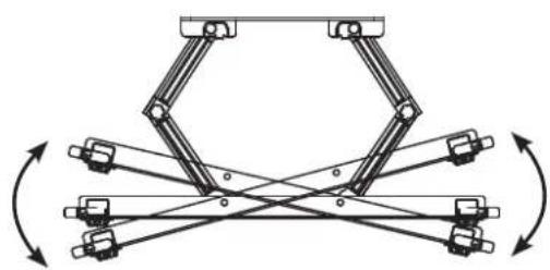
5 Setting the Lock Springs
— After securing the set to the bracket, pull down the lock springs at the bottom of the wall mounting bracket.
* Caution : If the wall mounting bracket is not attached securely, the set may fall off, resulting in damage or injury.
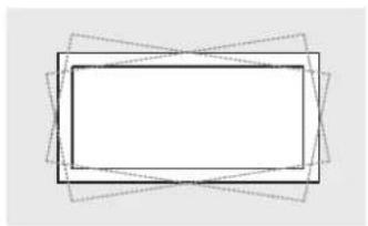
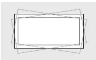
6 How to level the Display
- After installing the display, check to make sure it is level. (The product goes up or down according to the rotation direction of the screw.)
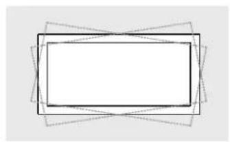
<400×200>
natural_image
Abstract geometric diagram with overlapping rectangles and dashed lines (no text or symbols)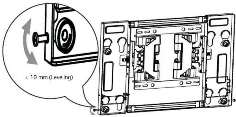
<300 x 200>
natural_image
Abstract geometric diagram with overlapping rectangles and dashed lines (no text or symbols)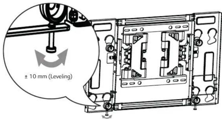
7 How to Organize Cables and Attach Protective Cushions
- Organize the cables as shown in the illustration. Please purchase a band for cable organization, or use the band that comes with the TV.
- Attach the protective cushions to minimize the impact between the wall and the TV in case they bump against each other when adjusting the angle. Attach them in the desired positions, as illustrated.
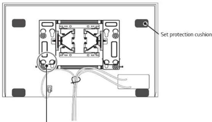
* Caution: Prevent the power cord and the cables from being pinched between the wall mounting bracket and the wall.

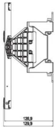
SPECIFICATIONS
natural_image
Diagram of a mechanical linkage system with multiple components and directional arrows (no text or labels)12 ± 2^ 15 ± 2^

natural_image
Mechanical linkage diagram showing multiple joints and linkages with rotational arrows (no text or labels)[Unit: mm]
MinimumMaximum
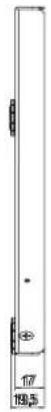
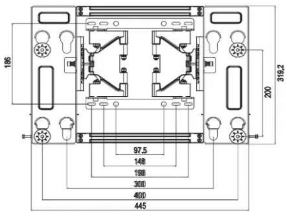
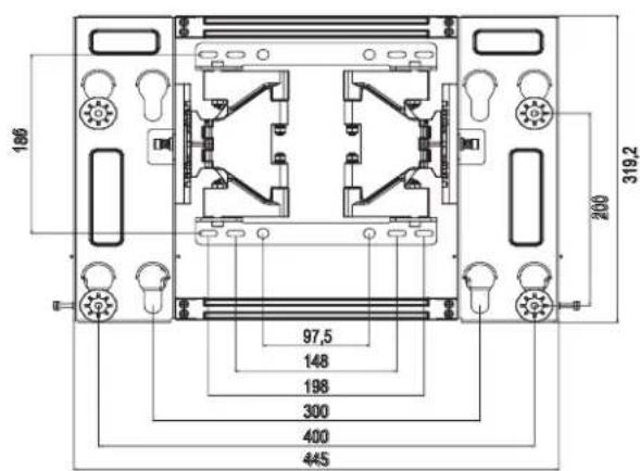
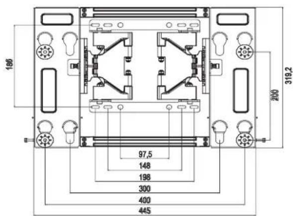
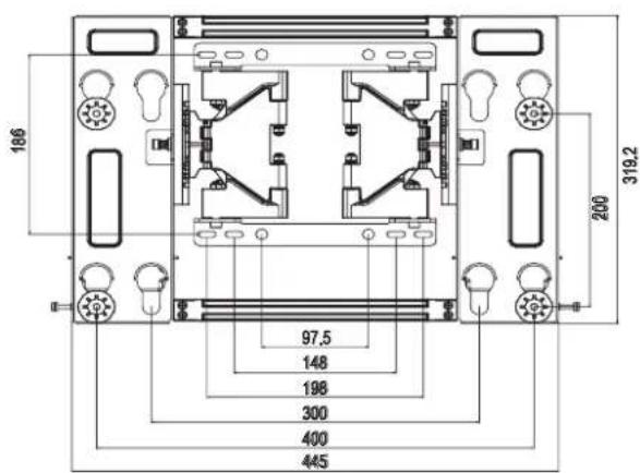
| Model name OTW420B | |
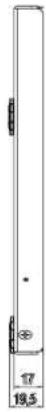
| Width (mm) 445 | |
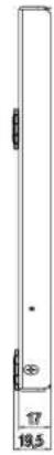
| Height (mm) 319.2 | |
| Depth (mm) 17 | |
| Product weight (kg) 2.7 | |
| Wall mounting bracket VESA specifications | 400 x 200300 x 200 |
| Max. tensile load (kg) 32 |

The model and serial number of the product is located on the back or one side of the product. Record it below should you ever need service.
MODEL
SERIAL
Supported Displays
(Please contact the retailers or refer to the TV owner's manual for applicable models.)
설치설명서
벽걸이 지지대
6 제품 수평 (기울기) 조정 방법
natural_image
Abstract geometric diagram with overlapping rectangles and dashed lines (no text or symbols)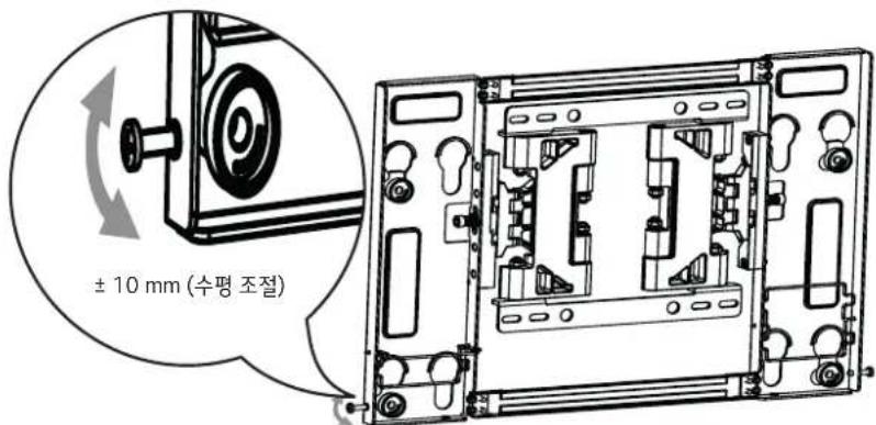
<300 x 200>
natural_image
Abstract geometric diagram with overlapping rectangles and dashed lines forming a star-like pattern (no text or symbols)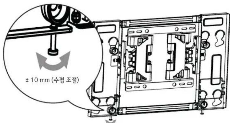
natural_image
Pure mechanical diagram showing a linkage mechanism with no text, numbers, or symbols12 ± 2^ 15 ± 2^
natural_image
Mechanical linkage diagram showing interlocking components with rotational arrows (no text or labels)[단위:mm]
natural_image
Technical line drawing of a mechanical device showing internal components and assembly (no text or symbols)6
natural_image
Simple geometric diagram with overlapping rectangles and dashed lines, no text or symbols present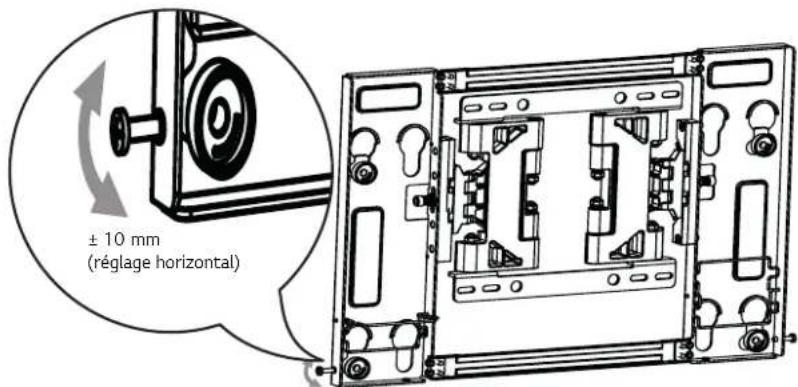
<300 x 200>
natural_image
Abstract geometric diagram with overlapping rectangles and dashed lines (no text or symbols)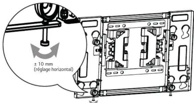
natural_image
Mechanical linkage diagram showing bidirectional motion between two robotic arms (no text or symbols)
Installationshandbuch
natural_image
Pure mechanical component diagram without any text, numbers, or symbolsnatural_image
Technical line drawing of a mechanical device with internal components and mounting brackets (no text or symbols)natural_image
Simple geometric diagram with overlapping rectangles and dashed lines, no text or symbols present.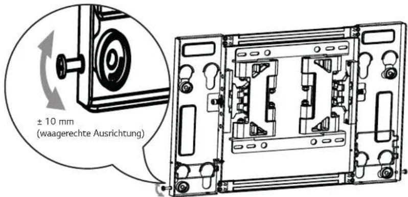
natural_image
Abstract geometric diagram with overlapping rectangles and diagonal lines (no text or symbols)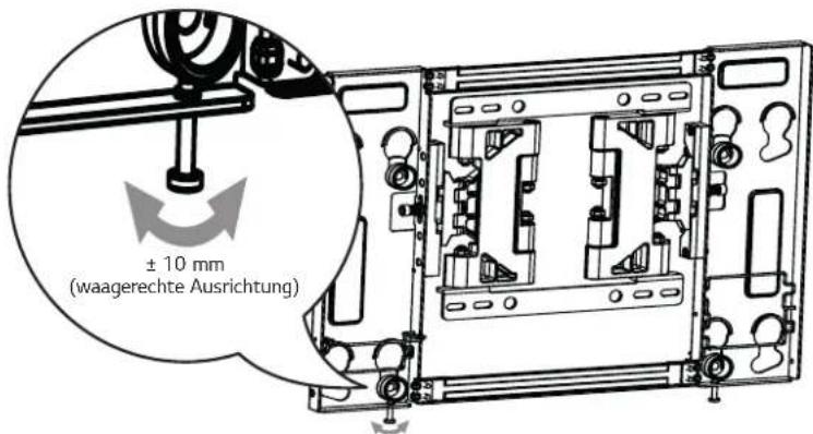
natural_image
Diagram of a mechanical linkage system with multiple components and a triangular frame (no text or symbols)12 ± 2^ 15 ± 2^

natural_image
Mechanical linkage diagram showing interlocking components with rotational arrows (no text or labels)[Einheit: mm]
MinimumMaximum

natural_image
Pure diagram of a mechanical component with no text, numbers, or symbolsnatural_image
Technical line drawing of a mechanical device with internal components and a magnified inset showing a rotating component (no text or symbols)natural_image
Simple geometric diagram with overlapping rectangles and diagonal lines (no text or symbols)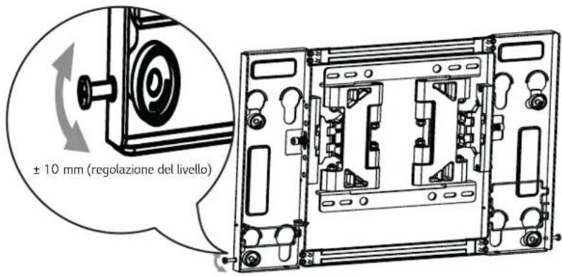
natural_image
Abstract geometric diagram with overlapping rectangles and dashed lines (no text or symbols)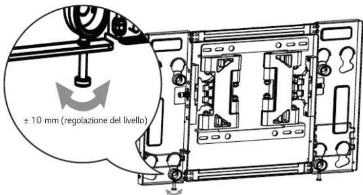
natural_image
Diagram of a mechanical linkage system with multiple arms and a central connector (no text or symbols)12 ± 2^ 15 ± 2^

natural_image
Mechanical linkage diagram showing interlocking components with rotational arrows (no text or labels)[Unità: mm]
MinimoMassimo

natural_image
Abstract geometric diagram with overlapping rectangles and dashed lines forming a cross (no text or symbols)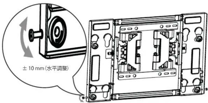
<300 x 200>
natural_image
Simple geometric diagram with overlapping rectangles and dashed lines, no text or symbols present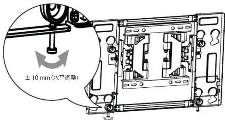
natural_image
Pure mechanical diagram showing intersecting rods and a triangular frame without any text or symbols12 ± 2^ 15 ± 2^

natural_image
Mechanical linkage diagram showing rotational motion with no text or symbols[单位:mm]
2 Como instalar as buchas e os parafusos
Siga as instruções
natural_image
Abstract geometric diagram with overlapping rectangles and lines (no text or symbols)
<300 x 200>
natural_image
Simple geometric diagram with overlapping rectangles and dashed lines, no text or symbols present.
natural_image
Diagram of a mechanical linkage system with multiple linkages and a triangular frame (no text or symbols)12 ± 2^ 15 ± 2^

natural_image
Mechanical linkage diagram showing interlocking components with rotational arrows (no text or labels)[Unidade: mm]
MínimoMáximo

natural_image
Technical line drawing of a computer case with internal components and a magnified inset showing a mechanical assembly (no text or symbols)natural_image
Abstract geometric diagram with overlapping rectangles and dashed lines forming a cross-like pattern (no text or symbols)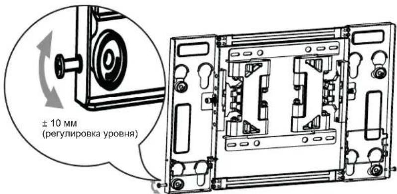
natural_image
Abstract geometric diagram with overlapping rectangles and dashed lines forming a cross-like pattern (no text or symbols)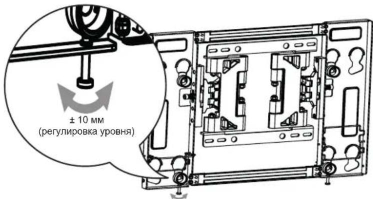
natural_image
Diagram of a mechanical linkage system with multiple linkages and a triangular frame (no text or symbols)12 ± 2^ 15 ± 2^

natural_image
Mechanical linkage diagram showing interlocking components with rotational arrows (no text or labels)natural_image
Abstract geometric diagram with overlapping rectangles and triangles (no text or symbols)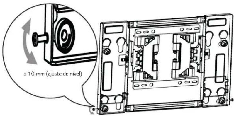
<300×200>
natural_image
Abstract geometric diagram with overlapping rectangles and dashed lines (no text or symbols)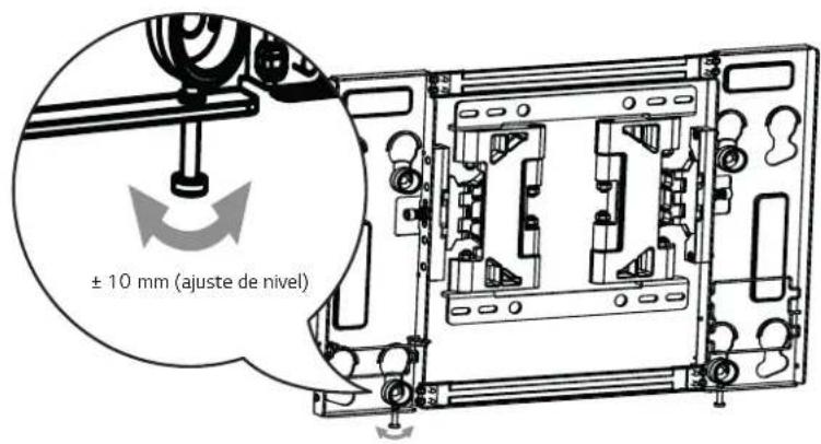
natural_image
Diagram of a mechanical linkage system with multiple linkages and a triangular frame (no text or symbols)12 ± 2^ 15 ± 2^

natural_image
Mechanical linkage diagram showing interlocking components with rotational arrows (no text or labels)[Unidad: mm]

Mínimo Máximo

natural_image
Abstract geometric diagram with overlapping rectangles and dashed lines (no text or symbols)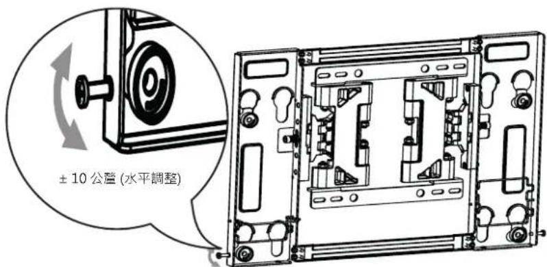
natural_image
Abstract geometric diagram with overlapping rectangles and dashed lines forming a star-like shape (no text or symbols)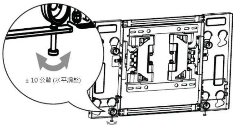
7 如何整理纜線及安裝防護軟墊
natural_image
Pure mechanical diagram showing intersecting rods and a triangular frame without any text or symbols12 ± 2^ 15 ± 2^
natural_image
Mechanical linkage diagram showing rotational motion with no text or symbols[單位:公釐]

最大
最小

- Printing specification
- Pagination sheet
- Wall mounting bracket
- COMPONENT
- IMPORTANT SAFETY INSTRUCTIONS
- Warning
- The product should be installed by a qualified professional specified by the retail store.
- When moving or replacing the product after installation, contact a qualified installer specified by the retail store.
- Be sure not to hang the power cable and signal cable on the back of TV when installing the wall-mounted TV.
- The product should be installed where its weight can be fully supported.
- Do not hang on this product, protect the product from severe impacts after the installation.
- Caution
- Follow the instructions in this manual to product properly.
- When installing the product, first check that the wall is strong enough. Use the anchors and screws provided.
- Do not clean the product with a wet towel, and do not place a heater, or humidifier beneath it.
- Make sure that the power cord is removed from the outlet before installing the product.
- To install or adjust the height of the product, two or more people are needed.
- When drilling holes into the wall, make sure you use a drill and drill bit with the specified diameter. Ensure that you also follow the instructions regarding the depth of the holes.
- Keep this product away from sprinklers, sensors, high-tension wires and power sources. Do not install it in a location where vibrations or impacts are likely to occur.
- Wear safety gloves when installing the product. Do not use your bare hands.
- BEFORE INSTALLATION
- INSTALLATION
- How to Attach the Brackets for the Product to the TV
- Work procedure
- 2
- How to attach to masonry walls
- Please follow the below direction.
- How to install the wall mounting bracket
- How to assemble the wall mounting bracket and display
- Setting the Lock Springs
- How to level the Display
- How to Organize Cables and Attach Protective Cushions
- 설치설명서
- 벽걸이 지지대
- 제품 수평 (기울기) 조정 방법
- 6
- Como instalar as buchas e os parafusos
- Siga as instruções
- 如何整理纜線及安裝防護軟墊
Brand : LG
Model : OTW420B
Category : Television