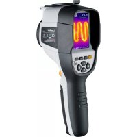
ThermoCamera Connect - Measuring equipment Laserliner - Free user manual and instructions
Find the device manual for free ThermoCamera Connect Laserliner in PDF.


| Product type | Infrared thermal camera |
| Brand | Laserliner |
| Model | ThermoCamera Connect |
| Dimensions (L x H x D) | 105 x 223 x 90 mm |
| Weight | 389 g (including battery pack) |
| Power supply | Li-ion battery 3.5 V – 4.2 V / 2000 mAh, charging via Micro USB 4.75 V – 5.50 V |
| Infrared sensor | Uncooled microbolometer, 220 x 160 pixels, 9 Hz, 8-14 μm |
| Measuring range | -20 °C to 350 °C |
| Accuracy | ±2 °C or ±2% of measured value |
| Thermal sensitivity | 0.07 °C @ 30 °C |
| Display | 3.2-inch TFT color display |
| Image modes | Infrared image, digital image, MIX image (3 blend levels) |
| Digital camera resolution | 640 x 480 pixels |
| Storage | Integrated SD card (more than 20,000 photos) |
| Wireless interface | WLAN IEEE 802.11 b/g/n, 2.4 GHz band, port 80, IP address 192.168.230.1 |
| Emissivity | Adjustable from 0.01 to 1.0 |
| Protection rating | IP54 |
| Working conditions | 0 °C to 45 °C, relative humidity 20-85% non-condensing |
| Battery life | Approximately 2 to 3 hours (depending on use) |
| Charging time | Approximately 3 to 4 hours |
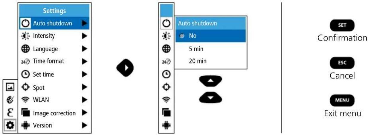
| Automatic shutdown | Adjustable: 5 minutes, 20 minutes, or off |
| Cleaning and maintenance | Clean with a slightly damp cloth, no solvents. Remove the battery before extended storage. Do not touch the lens. |
| Safety | Use only original accessories. Do not modify the device. Avoid strong electromagnetic fields. |
| General information | Compliant with RED directive 2014/53/EU and WEEE. Annual calibration recommended. |
Frequently Asked Questions - ThermoCamera Connect Laserliner
User questions about ThermoCamera Connect Laserliner
0 question about this device. Answer the ones you know or ask your own.
Ask a new question about this device
Download the instructions for your Measuring equipment in PDF format for free! Find your manual ThermoCamera Connect - Laserliner and take your electronic device back in hand. On this page are published all the documents necessary for the use of your device. ThermoCamera Connect by Laserliner.
USER MANUAL ThermoCamera Connect Laserliner
natural_image
Laser liner device with thermal imaging display showing temperature, humidity, and control buttons (no readable text or symbols beyond technical labels)
MIX-IMAGE
HOT SPOT / COLD SPOT MARKER
HOT SPOT / COLD SPOT MARKER

IR-SENSOR
220 x 160 px

9 FRAMES
PER SECOND

JPG
IMAGE
LI-ION BATTERY
COLOUR TFT

RECHARGE

CONNECT 192.168.230.1
Laserliner
DE
02
EN
14
NL
26
DA
38
FR
50
ES
IT
PL
FI
PT
SV
NO
TR
RU
UK
CS
ET
RO
BG
EL
!
natural_image
Technical illustration of a sewing machine with attached sensor and control panel (no text or symbols)4 Hauptmenü


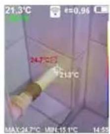

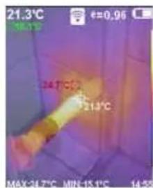

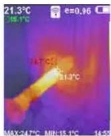


9 Aufnahme Bild
natural_image
Technical illustration of a laser cutting machine with no visible text or symbols on the device itself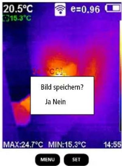
Completely read through the operating instructions, the „Warranty and Additional Information” booklet as well as the latest information under the internet link at the end of these instructions. Follow the instructions they contain. This document must be kept in a safe place and passed on together with the device.
Function / Application
The ThermoCamera Connect is used to visually display thermal patterns and enables non-contact measurement of surfaces by evaluating the radiation in the infrared wavelength range via the integrated non-chilled microbolometer. The imaging technology of the sensor provides a visual image of the temperatures surrounding the inspected object. The temperature differences can be visualised by colour-coding the individual temperatures in a thermogram with false colour display. Possible applications include locating overloads in electrical components, detecting overheating in mechanical components, pinpointing and analysing heating lines in walls and floors, assessing refrigerant and air conditioning systems and much more.
General safety instructions
- The device must only be used in accordance with its intended purpose and within the scope of the specifications.
- The measuring tools and accessories are not toys. Keep out of reach of children.
- Modifications or changes to the device are not permitted, this will otherwise invalidate the approval and safety specifications.
- Do not expose the device to mechanical stress, extreme temperatures, moisture or significant vibration.
- The device must no longer be used if one or more of its functions fail or the battery charge is weak.
- Use only genuine accessories. Use of inappropriate accessories will invalidate the warranty.
- The charging progress can be viewed by briefly pressing the ON/OFF button.
- The residual charge of batteries with a weak charge is shown in red.
- The battery can also be charged while using the device.
- Disconnect the power pack from the mains when the device is not in use.
- Never use extension cables in conjunction with the battery charger, or similar accessories not approved by the manufacturer, as this may result in a fire risk, the risk of an electric shock or injury to persons.
Safety instructions
Using electromagnetic radiation and RF wireless radiation
- Local operating restrictions – for example, in hospitals, aircraft, petrol stations or in the vicinity of people with pacemakers – may apply. Electronic devices can potentially cause hazards or interference or be subject to hazards or interference.
- The measuring accuracy may be affected when working close to high voltages or high electromagnetic alternating fields.
- The measuring device is equipped with a wireless interface.
– The measuring device complies with electromagnetic compatibility and wireless radiation regulations and limits in accordance with the RED 2014/53/EU. - Umarex GmbH & Co. KG hereby declares that the ThermoCamera Connect radio equipment complies with the essential requirements and other provisions of the European Radio Equipment Directive 2014/53/EU (RED). The EU Declaration of Conformity can be found in its entirety at the following address: http://laserliner.com/info?an=AGR
- This device complies with the CE limit values for radiation exposure as defined for uncontrolled environments. To avoid wireless radiation, this device should be used at a minimum distance of 20 cm from the body.
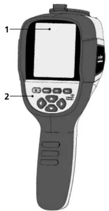
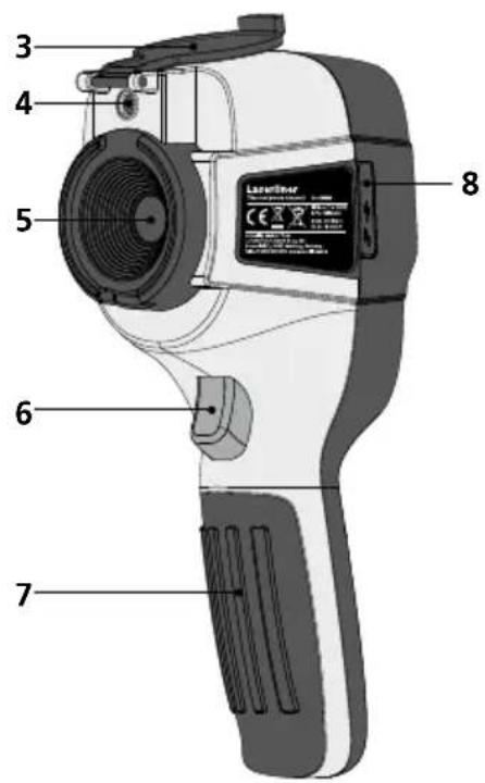
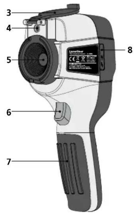
1 3,2" TFT colour display
2 Hot keys
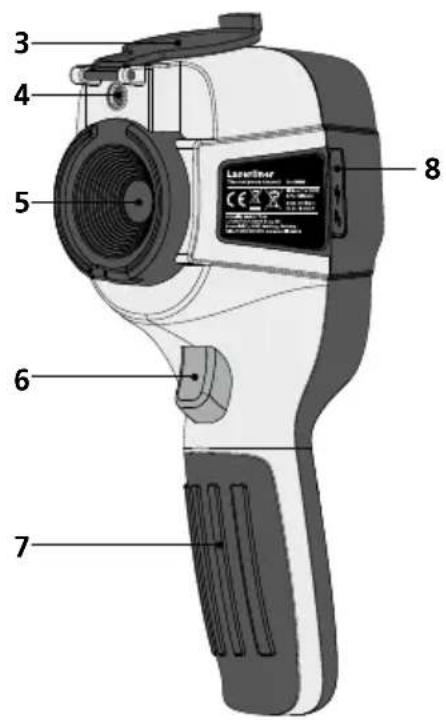
3 Lens cover
4 Camera
5 Infrared camera lens
6 Trigger: Capture
7 Battery compartment
8 Shaft
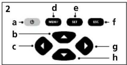
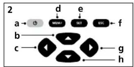
a ON/OFF
b Menu navigation
c Menu navigation / select digital image, overlay infrared / digital image and infrared image
d Open main menu / exit main menu (cancel) / save image
e Control menu
(confirmation) /
do not save image
flowchart
graph TD
    a --> b
    b --> c
    c --> d
    d --> e
    e --> f
    f --> g
    g --> h
f Control menu (cancel)
g Menu navigation / select digital image, overlay infrared / digital image and infrared image
h Menu navigation
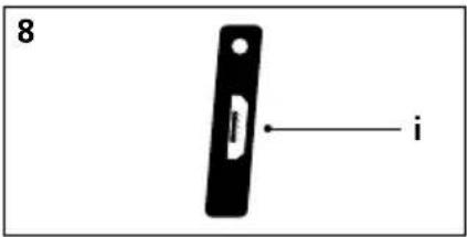
i Micro USB interface
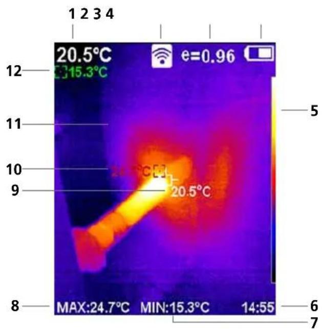
Standard measurement view
1 Temperature at centre of image
2 WLAN active
3 Set emissivity coefficient
4 Battery charge indicator
5 Color palette
6 Time
7 Min. temperature
8 Max. temperature
9 Temperature at centre of image
10 Max. temperature
11 Thermography image
12 Min. temperature
Laserliner
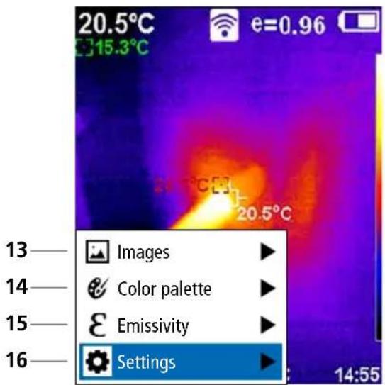
Main menu
13 Open media gallery
14 Change color palette
15 Set emissivity coefficient
16 Settings
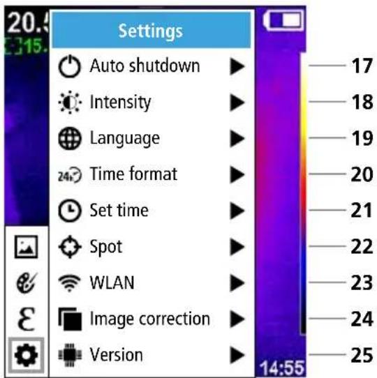
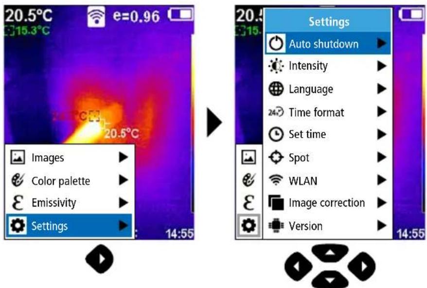
Main menu settings
17 Auto shutdown
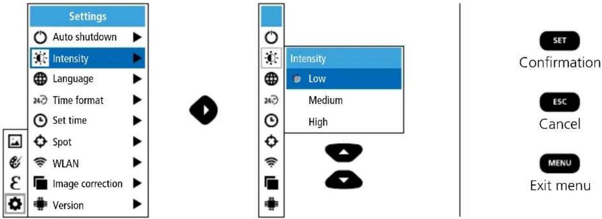
18 Display brightness
19 Menu language
20 Time format
21 Time settings
22 Spot (Measuring point)
23 WLAN connection ON/OFF
24 Image correction
25 Software version
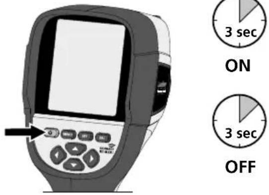
1 ON / OFF
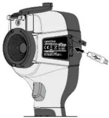
2 Charging the li-ion battery
To charge the Li-ion battery pack, plug the supplied USB cable into the charging socket „i“ and connect it to the USB 2.0 power supply unit.
Operation while charging is possible.
natural_image
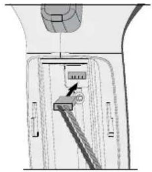
Technical line drawing of a mechanical device with labeled components (no readable text or symbols)3 Removing / inserting li-ion battery pack
Open battery compartment (7) and remove/insert the Li-ion battery pack. When inserting battery ensure correct polarity.
4 Main menu
General and measurement-specific settings can be made in the main menu. The menu is controlled with the four buttons (b, c, g, h).
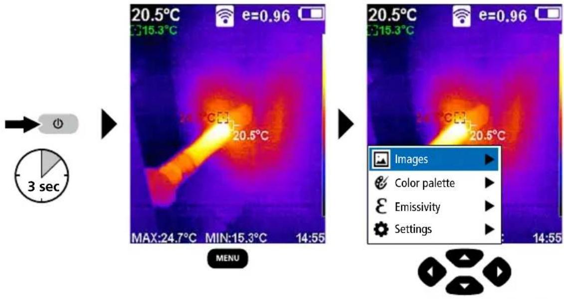
5.0 Settings
5.1 Settings: Auto shutdown
The device switches off automatically after a set period of inactivity.
5.2 Settings: Display brightness
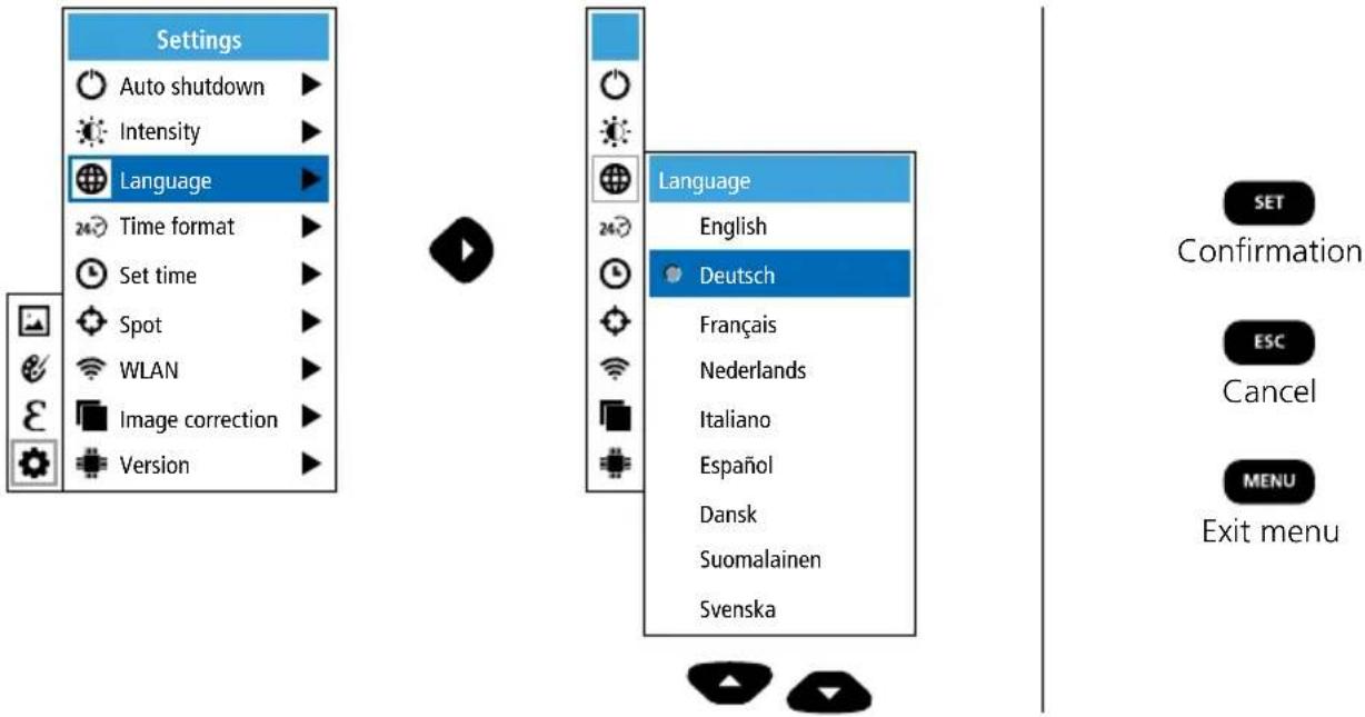
5.3 Settings: To set menu language EN / DE / FR / NL / IT / ES / DK / FI / SE
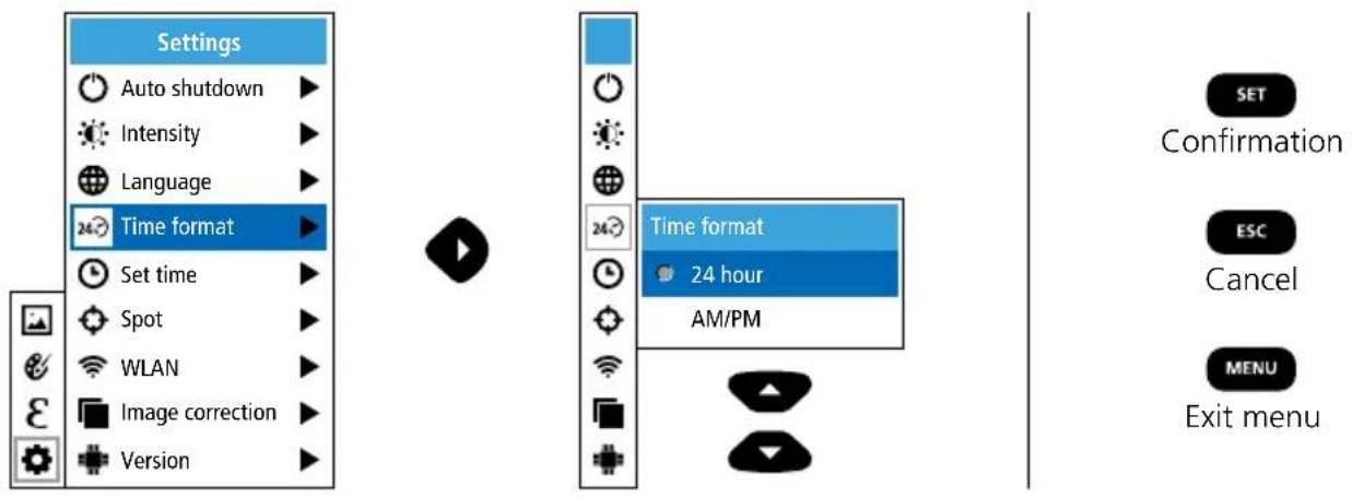
5.4 Settings: Time format
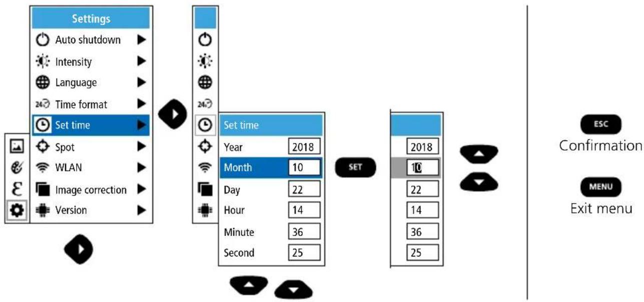
5.5 Settings: Set time
flowchart
graph LR
    A["Settings"] --> B["Auto shutdown"]
    A --> C["Intensity"]
    A --> D["Language"]
    A --> E["Time format"]
    A --> F["Set time"]
    F --> G["Spot"]
    F --> H["WLAN"]
    F --> I["Image correction"]
    F --> J["Version"]
    K["Set time"] --> L["Year 2018"]
    K --> M["Month 10"]
    K --> N["Day 22"]
    K --> O["Hour 14"]
    K --> P["Minute 36"]
    K --> Q["Second 25"]
    R["SET"] --> S["2018"]
    R --> T["10"]
    R --> U["22"]
    R --> V["14"]
    R --> W["36"]
    R --> X["25"]
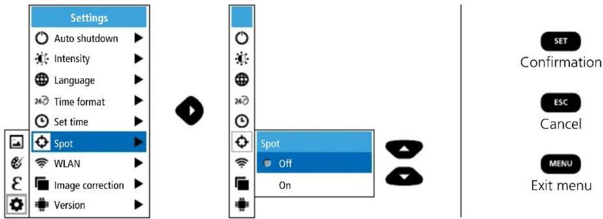
5.6 Settings: Spot (Measuring point)
The temperature is shown in the centre of the image as standard. Two spots can be added.
Max: highest temperature, Min: lowest temperature
5.7 Settings: WLAN connection
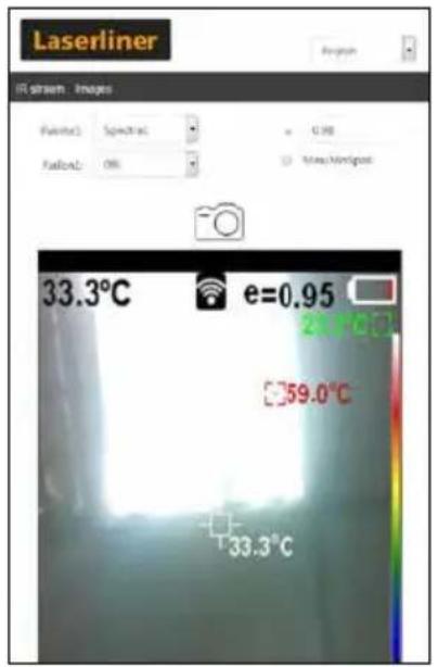
To evaluate the data, the ThermoCamera Connect can be connected via WLAN to a terminal device (desktop PC or mobile phone) with WLAN capabilities. For this purpose first select the required WLAN SSID on the device (MAC:MMMMMM). MMMMMM corresponds to the MAC address.
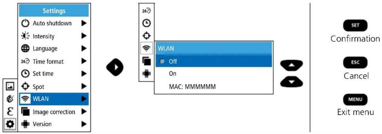
The connection with the corresponding SSID is then set up at the terminal device. With any modern browser the ThermoCamera Connect makes the data available under the IP-address 192.168.230.1 Port 80.
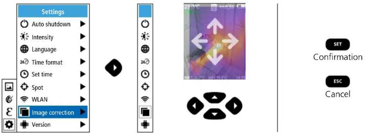
5.8 Settings: Image correction
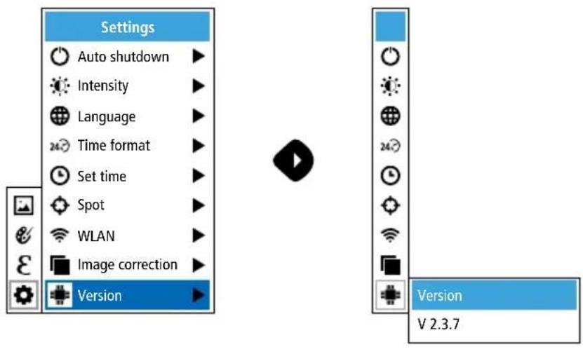
5.9 Settings: Version
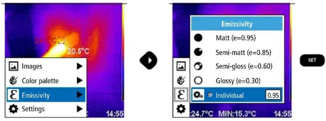
6.0 Emissivity
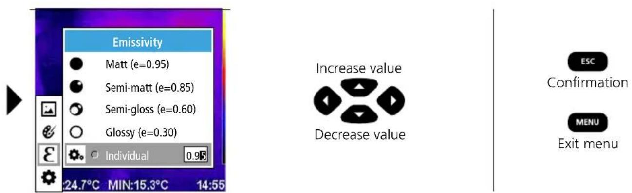
Before each use, check the settings for infrared measurement and adjust them to the respective measuring situation to ensure accurate measurements. Pay particular attention to the general parameters for the emissivity coefficient.
6.1 Emissivity: Emissivity coefficient
The level of infrared emissions given off by everything depends on the specific material and surface. This factor is determined by the emissivity coefficient (0.10 ... 1.0). For accurate measurements, it is absolutely essential that the emissivity coefficient is set first. The emissivity coefficient can either be custom set or selected based on the predefined emissivity coefficients from the material list.
Emissivity table (reference values with tolerances)
Metals
| Alloy A3003 | Iron | Steel | |||
| Oxidised | 0.20 | Oxidised | 0.75 | Alloy (8% nickel, 18% chromium) | 0.35 |
| Roughened | 0.20 | With rust | 0.60 | ||
| Aluminium | Iron, cast | Galvanised | 0.28 | ||
| Oxidised | 0.30 | Non-oxidised | 0.20 | Oxidised | 0.80 |
| Polished | 0.05 | Molten mass | 0.25 | Heavily oxidised | 0.88 |
| Brass | Iron, forged | Freshly rolled | 0.24 | ||
| Polished | 0.30 | Matt | 0.90 | Rough, flat surface | 0.96 |
| Oxidised | 0.50 | Lead | Rusty, red | 0.69 | |
| Chromium oxide 0.81 | Rough | 0.40 | Sheet, nickel plated | 0.11 | |
| Copper | Platinum | Sheet, rolled | 0.56 | ||
| Oxidised | 0.72 | Black | 0.90 | Stainless steel | 0.45 |
| Copperoxide | 0.78 | Steel | Zinc | ||
| Inconel | Cold rolled | 0.80 | Oxidised | 0.10 | |
| Oxidised | 0.83 | Ground plate | 0.50 | ||
| Electropolished | 0.15 | Polished plate | 0.10 |
Nonmetals
| Asbestos 0.93 | Gravel | 0.95 | PaperAll colours | 0.96 | |
| Asphalt 0.95 | Grit | 0.95 | |||
| Basalt 0.70 | Gypsum | 0.88 | PlasticTranslucentPE, P, PVC | 0.950.94 | |
| Brick, red 0.93 | Gypsum cardboard | 0.95 | |||
| Carborundum 0.90 | Heat sinkBlack, anodized | 0.98 | Quartz glass | 0.93 | |
| Cement 0.95 | Human skin | 0.98 | RubberHardSoft, grey | 0.940.89 | |
| Ceramics 0.95 | IceClearWith heavy frost | 0.970.98 | Sand | 0.95 | |
| ChinaBrilliant white With glaze | 0.730.92 | Laminate | 0.90 | Screed | 0.93 |
| Clay 0.95 | Lime | 0.35 | Snow | 0.80 | |
| CoalNon-oxidised | 0.85 | Lime malm brick | 0.95 | Soil | 0.94 |
| Concrete, plaster, mortar | 0.93 | Limestone | 0.98 | Tar | 0.82 |
| Cotton 0.77 | MarbleBlack, dull finishGreyish, polished | 0.940.93 | Tar paper 0.92 | ||
| Earthenware, matt 0.93 | Transformer paint | 0.94 | |||
| Fabric 0.95 | Masonry | 0.93 | Wallpaper, light-coloured | 0.89 | |
| Glass 0.90 | PaintBlack, mattHeat-resistantWhite | 0.970.920.90 | Water | 0.93 | |
| Glass wool 0.95 | WoodUntreatedBeech, planed | 0.880.94 | |||
| Graphite | 0.75 |
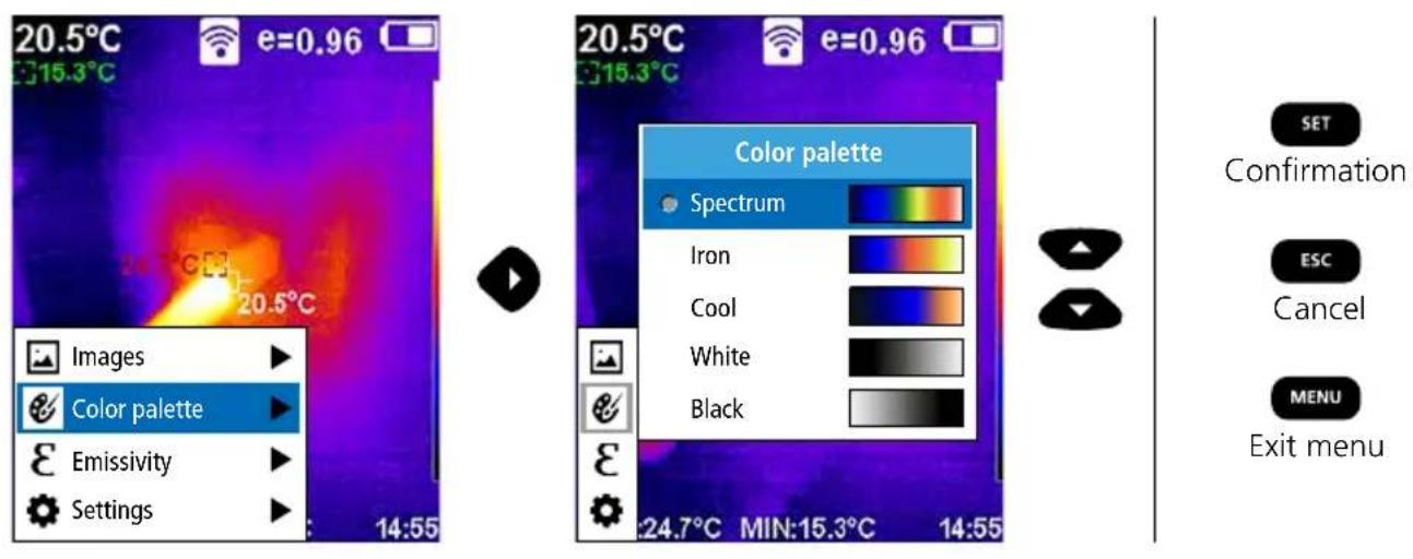
7 Colour ranges IR image
You can choose from several standard colour ranges to represent the measured infrared temperatures. Depending on the colour palette, the measured temperatures are adjusted within the current image section and displayed in the respective colour space. The bargraph for the respective minimum/maximum temperatures of the entire image serves as a reference for the corresponding temperature/colour mapping.
ThermoCamera Connect
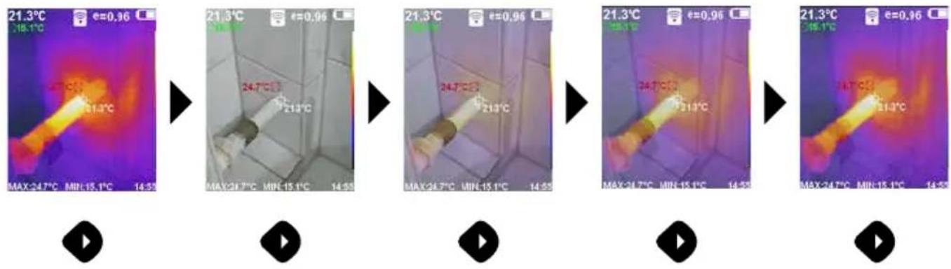
8 Image modes
There are 5 image modes to choose from.
A. IR image (IR)
B. Digital image (Visible)
C. Digital image with IR image overlay (MIX), level 1
D. Digital image with IR image overlay (MIX), level 2
E. Digital image with IR image overlay (MIX), level 3
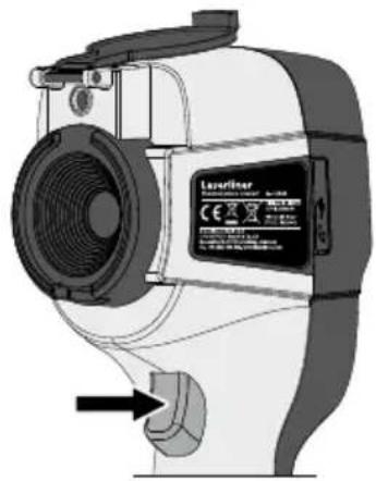
9 Capture image
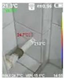
Using the „Trigger“ button (6), users can take images of any measurement situation for the subsequent documentation.
natural_image
Technical illustration of a laser cutting machine with no visible text or symbols on the device itself
10 Media gallery / to delete recording
All images recorded with the ThermoCamera Connect can be accessed in the media gallery.
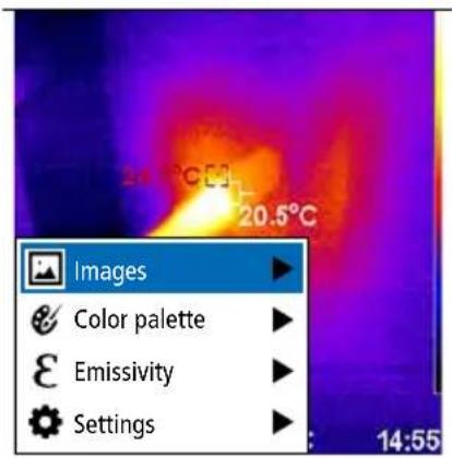

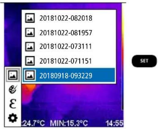
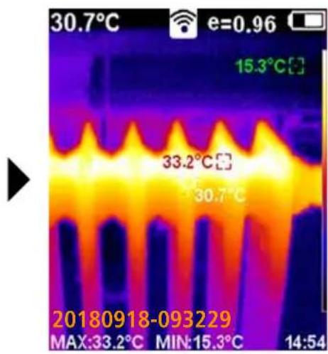


The image will be deleted immediately by pressing the MENU button. There are no safety prompts.
Information on maintenance and care
Clean all components with a damp cloth and do not use cleaning agents, scouring agents and solvents. Remove the battery pack before storing for longer periods. Store the device in a clean and dry place. Do not touch the lens.
Calibration
The meter needs to be calibrated and tested on a regular basis to ensure it produces accurate measurement results. We recommend carrying out calibration once a year.
EU directives and disposal
This device complies with all necessary standards for the free movement of goods within the EU.
This product is an electric device and must be collected separately for disposal according to the European Directive on waste electrical and electronic equipment. Further safety and supplementary notices at: http://laserliner.com/info?an=AGR

| IR sensor Resolution: 220 x 160 pixels, uncooled microbolometer, 9 Hz, 8-14 μm | ||
| IR optics High-quality IR-lens, | 27° x 35° (FOV), fixed focus, working area: 0.5 m ... 20 m | |
| Thermal sensitivity 0.07°C @ 30°C | ||
| Precision ± 2°C or ± 2% of measured value | ||
| Measurement range -20°C ... 350°C | ||
| Display 3,2" colour TFT | ||
| Image modes Infrared image, digital image, MIX image | ||
| Digital camera Resolution: 640 x 480 pixels | ||
| Format JPEG format | ||
| Memory function Integrated SD | memory (more than 20.000 images) | |
| Interface WLAN | ||
| Ports Micro USB charging | ||
| Emissivity coefficient 0.01 - 1.0 adjustable | ||
| Protection class IP54 | ||
| Operating conditions 0°C ... 45°C, max. humidity 20 ... 85% rH, no condensation, max. working altitude 2000 m above sea level | ||
| Storage conditions | -20°C ... 60°C, max. humidity 85% rH | |
| Radio module operating data | WLAN standard | IEEE 802.11 b/g/n |
| Frequency band | 2.400 - 2.4835 GHz (IEEE 802.11 b/g/n) | |
| Radio channels | Channel 9 | |
| Transmit power | 17 dBm max. | |
| Transmission rate | IEEE 802.11 b to 11 Mbps IEEE 802.11 g/n to 54 Mbps (at 15 ± 2 dBm) | |
| Safety | Open | |
| Local server mode | IP address 192.168.230.1; HTTP; no DHCP | |
| Port | 80 | |
| Automatic switch-off | Adjustable: 5 minutes / 20 minutes / no auto power off | |
| Power supply | Li-Ion pack battery 3.5V - 4.2V / 2000 mAh Micro USB 4.75V - 5.50V | |
| Charging time Approx. 3 - 4 h | ||
| Operating time | Approx. 2 - 3 h (depending on use) | |
| Dimensions (W x H x D) | 105 x 223 x 90 mm | |
| Weight | 389 g (incl. battery pack) | |
!
1 3,2" TFT-kleurendisplay
2 Directe toetsen
3 Lensbescherming
4 Camera
5 Infrarood-cameralens
6 Trigger: Opname
7 Accuvakje
8 Schacht
2 Li-ion-occupack opladen
natural_image
Technical line drawing of a handheld device with labeled components (no readable text or symbols)natural_image
Technical diagram of a mechanical assembly with no visible text or symbols4 Hoofdmenu
natural_image
Thermal imaging view showing heat distribution with temperature scale (no text or symbols on main image)

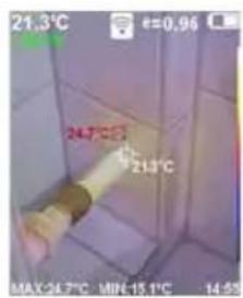

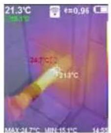

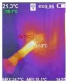


9 Opname beeld
natural_image
Technical illustration of a laser cutting machine with no visible text or symbols on the device itself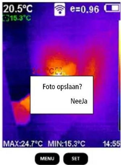
10 Mediagalerij / opnames wissen
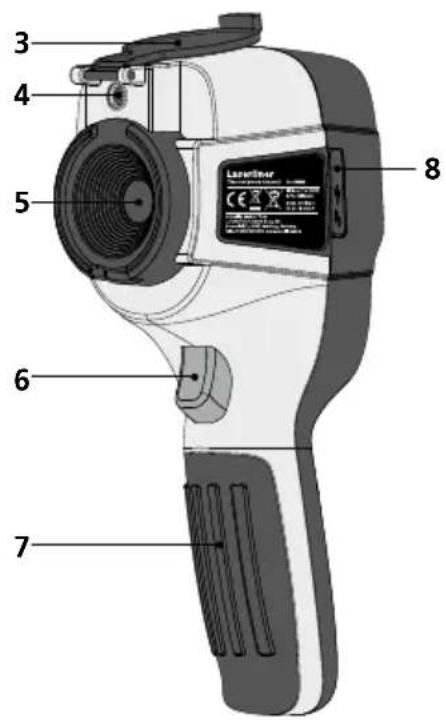
1 3,2" TFT-farvedisplay
2 Direkt-knapper
3 Linsebeskyttelse
4 Kamera
5 Infrarød-kameralinse
6 Trigger: Optagelse
7 Batterirum
8 Skakt
natural_image
Technical illustration of a mechanical device with labeled components (no readable text or symbols)4 Hovedmenu
Via hovedmenuen kan der foretages både generelle og målespecifikke indstillinger. Menuen kan styres via de fire direkt-knapper (b, c, g, h).
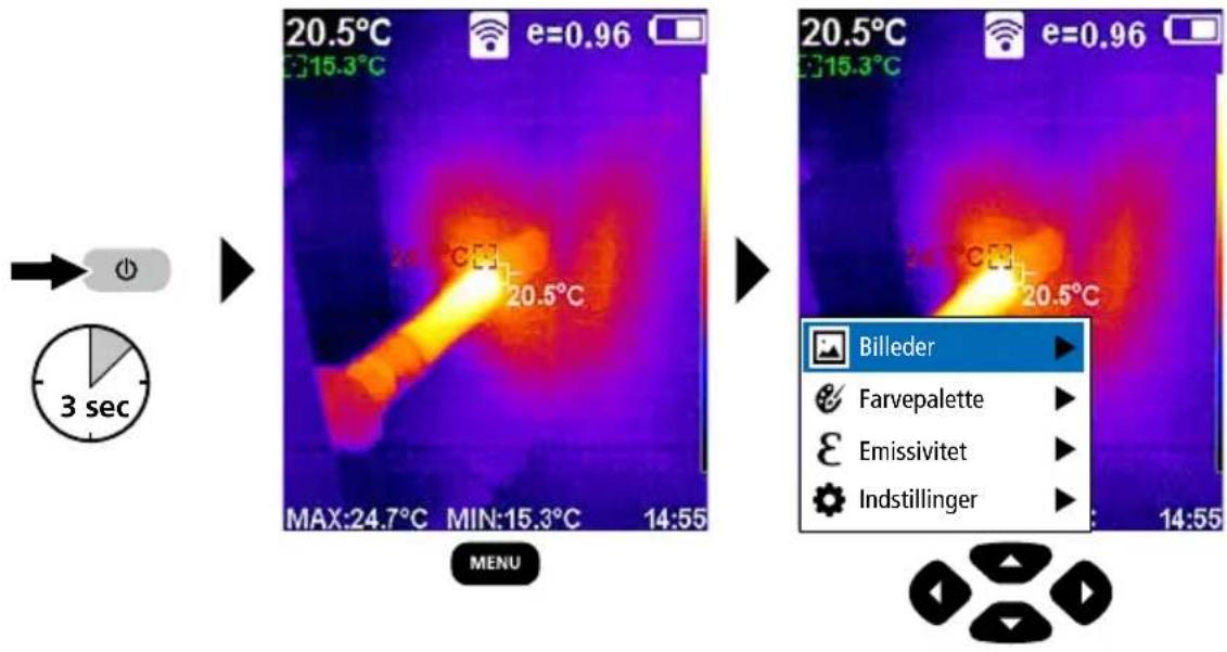
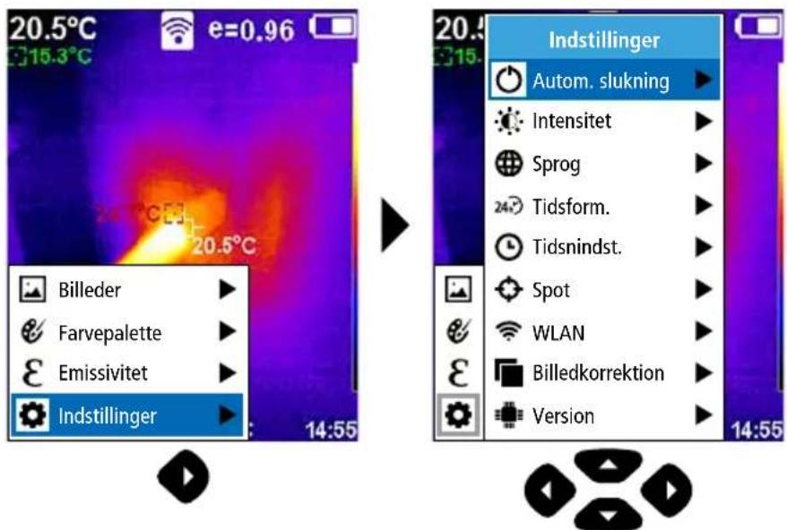
5.0 Indstillinger


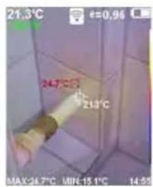

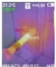

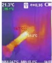


9 Optagelse billede
natural_image
Technical illustration of a laser cutting machine with no visible text or symbols on the device itself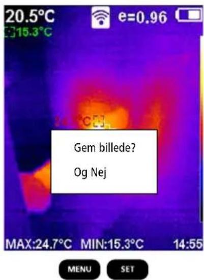
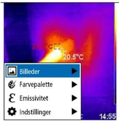
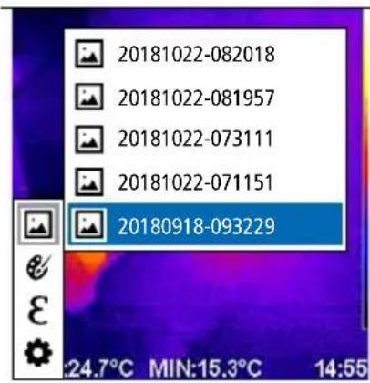
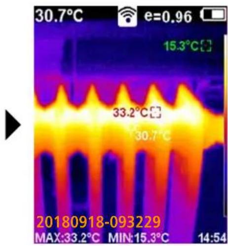
10 Mediegalleri / Slet optagelser
I mediegalleriet kan man kalde alle de billeder, som er optaget med Thermo-Camera Connect.


flowchart
graph TD
    a --> o["○"]
    o --> MENU
    MENU --> d
    d --> e
    e --> SET
    SET --> f
    b --> c
    c --> g
    g --> h

natural_image
Technical line drawing of a mechanical device with no visible text or symbols4 Menu principal
natural_image
Thermal imaging view showing heat distribution with temperature scale (no text or symbols on the image itself)
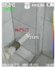


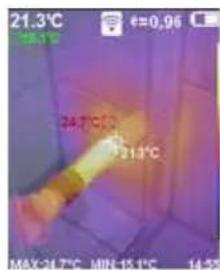

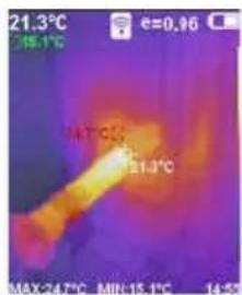


9 Prise d'une photo
natural_image
Technical illustration of a laser cutting machine with no visible text or symbols on the device itself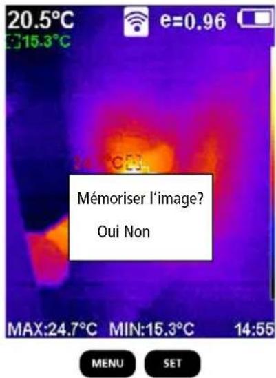
SERVICE


Umarex GmbH & Co. KG
-Laserliner-
- Hauptmenü
- Aufnahme Bild
- Function / Application
- General safety instructions
- Safety instructions
- Standard measurement view
- Laserliner
- Main menu
- Main menu settings
- Charging the li-ion battery
- Removing / inserting li-ion battery pack
- Main menu
- Settings
- Settings: Auto shutdown
- Settings: Display brightness
- Settings: To set menu language EN / DE / FR / NL / IT / ES / DK / FI / SE
- Settings: Spot (Measuring point)
- Settings: WLAN connection
- Settings: Image correction
- Emissivity
- Emissivity: Emissivity coefficient
- Emissivity table (reference values with tolerances)
- Colour ranges IR image
- ThermoCamera Connect
- Image modes
- Capture image
- Media gallery / to delete recording
- Information on maintenance and care
- Calibration
- EU directives and disposal
- Li-ion-occupack opladen
- Hoofdmenu
- Opname beeld
- Mediagalerij / opnames wissen
- Hovedmenu
- Indstillinger
- Optagelse billede
- Mediegalleri / Slet optagelser
- Menu principal
- Prise d'une photo
- SERVICE
- Umarex GmbH & Co. KG
Brand : Laserliner
Model : ThermoCamera Connect
Category : Measuring equipment