
COMpact 4000 - Phone Auerswald - Free user manual and instructions
Find the device manual for free COMpact 4000 Auerswald in PDF.
| Product type | Telecommunication system (PBX) |
| Brand | Auerswald |
| Model | COMpact 4000 |
| Dimensions (W x H x D) | 334 x 331 x 94.5 mm |
| Weight | 1.6 kg (base unit) |
| Power supply | 230 VAC +/- 10%, 50 Hz, 0.5 A max, 6-48 W |
| Ethernet ports | 1 (RJ-45, 10/100 Mbit/s) |
| USB ports | 1 (USB-A Host, High Speed V2.0) |
| ISDN ports | 2 (S0/UP0, RJ-45 or spring terminals) |
| Internal analog ports | 8 (spring terminals, 2 wires) |
| Expansion slots | 2 (for COMpact 2BRI or 2FXO modules) |
| Internal line capacity | 20 max. (analog, VoIP and ISDN) |
| External channels | 10 max. (analog, VoIP and ISDN) |
| VoIP channels | 12 |
| Voicemail channels | 4 |
| Fax channels | 1 |
| Operating temperature | 0 to +40 °C |
| Ambient humidity | 10 to 90%, non-condensing |
| Cleaning | Slightly damp or antistatic cloth |
| Manufacturer warranty | 24 months |
| Repairability | Repairable modules, spare parts available 5 years after end of production |
Frequently Asked Questions - COMpact 4000 Auerswald
User questions about COMpact 4000 Auerswald
0 question about this device. Answer the ones you know or ask your own.
Ask a new question about this device
Download the instructions for your Phone in PDF format for free! Find your manual COMpact 4000 - Auerswald and take your electronic device back in hand. On this page are published all the documents necessary for the use of your device. COMpact 4000 by Auerswald.
USER MANUAL COMpact 4000 Auerswald
You will find the "Advanced Information" manuals in the configuration manager and on our website. After a firmware update you usually require a new version of the manuals. You will find this on our website. (en)
Microsoft, Windows and Windows Server are trademarks of the Microsoft Corporation registered in the U.S.A. and/or other countries. All other trademarks mentioned are the property of the corresponding manufacturer.
Licenses
Please read the Auerswald license before using your Auerswald Product or downloading the software update accompanying this license.
The software included in this product contains parts of copyrighted software that is subject to the GPL, the LGPL or other licenses. The licenses can be found in the configuration manager under Overviews > Auerswald license and Open source licenses.
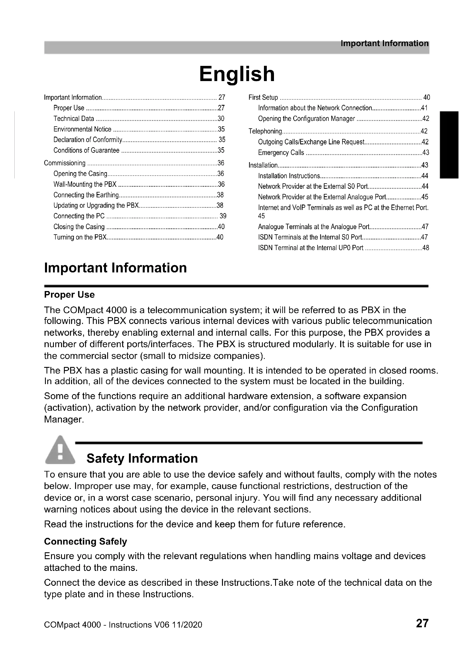
Deutsch 3
English 27
Espanol 50
EAAynikα 76
Francais 101
Italiano 127
Nederlands 151
Polski 175
Deutsch
Environmental Notice 35
Declaration of Conformity 35
Conditions of Guarantee 35
Commissioning 36
Opening the Casing 36
Wall-Mounting the PBX 36
Connecting the Earthing. 38
Updating or Upgrading the PBX. 38
Connecting the PC 39
Closing the Casing 40
Turning on the PBX. 40
First Setup 40
Information about the Network Connection. 41
Opening the Configuration Manager 42
Telephoning. 42
Outgoing Calls/Exchange Line Request. 42
Emergency Calls 43
Installation. 43
Installation Instructions 44
Network Provider at the External S0 Port. 44
Network Provider at the External Analogue Port. 45
Internet and VoIP Terminals as well as PC at the Ethernet Port. 45
Analogue Terminals at the Analogue Port. 47
ISDN Terminals at the Internal S0 Port. 47
ISDN Terminal at the Internal UPO Port 48
Important Information
Proper Use
The COMpact 4000 is a telecommunication system; it will be referred to as PBX in the following. This PBX connects various internal devices with various public telecommunication networks, thereby enabling external and internal calls. For this purpose, the PBX provides a number of different ports/interfaces. The PBX is structured modularly. It is suitable for use in the commercial sector (small to midsize companies).
The PBX has a plastic casing for wall mounting. It is intended to be operated in closed rooms. In addition, all of the devices connected to the system must be located in the building.
Some of the functions require an additional hardware extension, a software expansion (activation), activation by the network provider, and/or configuration via the Configuration Manager.

Safety Information
To ensure that you are able to use the device safely and without faults, comply with the notes below. Improper use may, for example, cause functional restrictions, destruction of the device or, in a worst case scenario, personal injury. You will find any necessary additional warning notices about using the device in the relevant sections.
Read the instructions for the device and keep them for future reference.
Connecting Safely
Ensure you comply with the relevant regulations when handling mains voltage and devices attached to the mains.
Connect the device as described in these Instructions. Take note of the technical data on the type plate and in these Instructions.
Important Information
Plug the connecting cables of the PBX only into designated and expertly installed sockets.
Only use original accessories and original replacement parts.
Work on active, contact-hazardous parts is only permitted after creating a voltage-free state. Working close to active parts is only permitted if these parts are voltage-free or are protected against direct contact.
Pull out the PBX's power plug before instructing a qualified electrician to open the casing, to install the expansion modules, or to switch or connect equipment. Also disconnect the device from additional power sources (e.g. a UPS, if installed).
Wait for the discharge of any capacitor in the device after disconnecting it from the main power supply. The electrolytic capacitors in the switch-mode power supply and the ringing voltage circuitry can remain charged for a long time.
Do not touch the PBX or any devices connected to it during an electrical storm.
Divert electrostatic charges from yourself before touching the circuit boards with your hands or any tools. To do this, touch a metal object, preferably earthed, such as the PBX's earthing terminal, the 19" casing, or a computer casing.
Hire a qualified electrician to lay the cables within the building – including the cable to the door terminal.
Safe Usage
Only operate the device when the casing is closed.
For some installation and maintenance work it is necessary to open the PBX while it is in operation (qualified electrician only). Make sure that the PBX is never left unattended while running with an open casing.
Only operate the device when it is mounted on the wall.
Never cover the vent slots of the casing.
Protect the devices by installing overvoltage protection.
If possible, provide a separate electric circuit for the connection that supplies the PBX.
Location Characteristics
Only operate the PBX in closed, dry rooms.
Mount the PBX close to an earth wire (potential compensation bar of the house installation or protective earth conductor). Connect the PBX's earth connection to the earth wire with a connecting cable whose conductor diameter is at least 2.5mm
Do not expose the device to direct sunlight.
Avoid mechanical loads (e. g. vibrations).
Avoid the proximity of devices that generate electro-magnetic fields (e.g. radio sets, professional radio equipment, amateur radio equipment, mobile phones, DECT systems, etc).
Protect the PBX from dirt, excessive dust, condensation caustic liquids and steam.
Note the threshold values indicated in the technical data for voltage, electricity, performance, ambient temperature, and moisture.
Prevent unauthorised access to the PBX and its programming. This installation is not intended for use in areas children could possibly be near.
Limitations on Use
Do not put a damaged PBX into operation.
Do not touch the PBX or any devices connected to it during an electrical storm.
The device is not designed, manufactured, or intended for use or resale, in environments that require fail-safe performance, such as in the operation of life-support systems and/or nuclear facilities. The device may only be used for these purposes with prior written permission from the manufacturer in each individual case.
Do not make any structural changes to the device.
Necessary Knowledge for Configuration
Only a qualified electrician may open the casing, perform installation work within an open casing or service work using the buttons inside the casing. If necessary, commission a specialist to perform this work.
Incomplete or incorrect configuration can be hazardous to people, if for example emergency calls cannot be performed.
The configuration of the product is made via an integrated web server whose pages are called via web browser. The user interface of the web server (Configuration Manager) is available in English and German.
Repair

Warning: Unauthorised changes to the device can damage the PBX or breach security and EMC regulations.
- Always have a professional carry out repairs. Please contact your qualified electrician or the manufacturer directly.
Cleaning

Caution: Liquid that penetrates the casing can cause life-threatening electric shocks and can damage or destroy the PBX.
- Only clean the device with a slightly damp cloth or an anti-static cloth.
- When cleaning the casing, make sure that no liquid enters the casing.
Data Protection
Take suitable measures for protecting your data and the PBX against misuse.
Never tell anyone the user names, passwords, PINs, or the public IP address of the PBX. This applies to postings in forums and communities, router service logs and Wireshark traces.
Consistently use all available options for assigning passwords and PINs. Do not use passwords and PINs that are easy to guess, such as birthdays or anniversaries.
Use the available permissions (programming authorisation, exchange line authorisations, restricted numbers, etc.).
Important Information
Check your PBX's call data management and your NAT router's logs regularly for inconsistencies.
You will find more information about protecting the system from misuse on the Internet pages on the pages of the German Federal Office for Information Security (see www.bsi.bund.de, with search term TK-Anlagen).
| Technical Data Power Supply | |
| Rated voltage 230 VAC +/-10 %, 50 Hz | |
| Rated current Max. 0.5 A | |
| Protection class I | |
| Power Min. 6 W, max. 48 W | (depending on the configuration level of the PBX) |
| Expansion modules Power supply from the PBX | |
Environmental Requirements
| Operation 0 to +40° Celsius | Protect unit against direct sunlight! |
| Operating the modules Installed | in the PBX casing |
| Storage and shipping -20 to +70° Celsius | |
| Humidity 10 to 90%, non-condensing | |
Connection Options on the Basic Unit
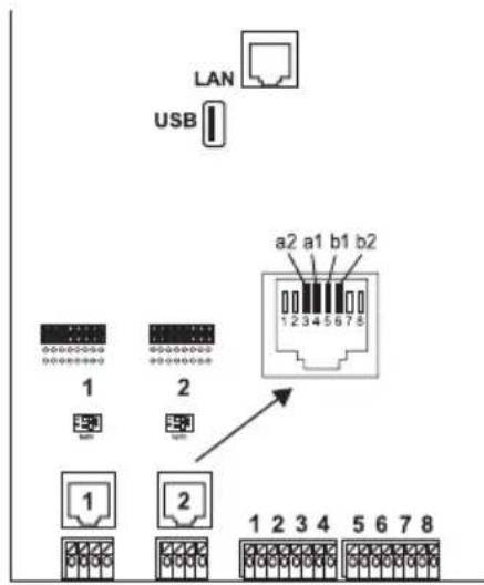
1 Ethernet port, connection via RJ-45 socket, 4 VoIP channels for internal IP and Internet telephony, SIP-compliant in accordance with RFC 3261; support for VoIP Codes G.711 (i-Law/a-Law), G.726, iLBC thereof one channel usable for voice mail functions with one voice mailbox)
Important: It is not possible to use the voice mail channel without inserted USB memory stick (not included in the scope of delivery).
1 USB host port, connection via USB A socket
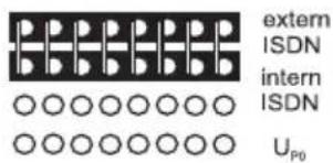
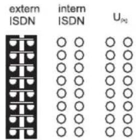
2 ISDN ports (1, 2), connection via RJ-45 socket or spring clamp connection (4-core S_0 , 2-core UP0 ), via jumper optionally switchable as an external S_0 port, internal S_0 port and internal UP0 port via DIP switch terminators switchable
8 internal analogue ports (1, 2, 3, 4, 5, 6, 7, 8), connection via spring clamp connection (2-core)
Extension Options on the Basic Unit
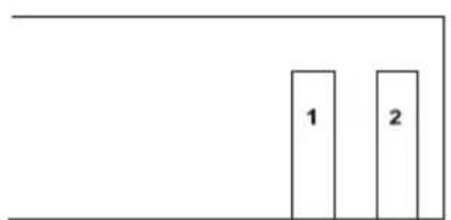
2 variable slots (slot 1, 2) for the modules:
- COMpact 2BRI Module
- COMpact 2FXO Module
Connection Options on the COMpact 2BRI Module
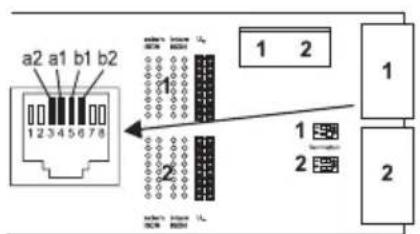
2 ISDN ports (1, 2), connection via RJ-45 socket or spring clamp connection (4-core S_0 , 2-core UP0 ), via jumper optionally switchable as an external S_0 port, internal S_0 port and internal UP0 port via DIP switch terminators switchable
Connection Options on the COMpact 2FXO Module
2 external analogue ports (1, 2), connection via RJ-45 socket or spring clamp connection (2-core)
Additional Extensions
| Door terminal The PBX can only | be expanded correspondingly by connecting suitable accessories at the Ethernet port and the internal analogue port. |
| Relay/actuator | |
| Switch input | |
| Announcement output |

Note: Modules for retrofitting with an S_2M port are not available for this PBX.
Demarcations, Maximum Number
| Internal subscriber connections analogue, VoIP and ISDN (internal S0 port corresponds to two internal subscriber connections) | 20 |
| External analogue, VoIP and ISDN channels 10 | |
| External S0 ports 3 | |
| VoIP channels 12 | |
| Voice mail channels 4 | |
| Fax channels 1 | |
| Additional devices (IP switch relays/boxes, announcement outputs, a/b and IP door terminals) | 16 |
| a/b and IP door terminals 8 | |
| Announcement outputs (e. g. a/b Audioboxes) 4 | |
| Relays/actuators (as part of additional devices) 24 | |
| Feeder for all S0/Up0/a/b ports 24 W |
Internal Analogue Port for Analogue Terminals
| Type of dialling Pulse or tone dialling | |
| Open-circuit voltage Max. 40 VDC | |
| Loop current | Approx. 23 mA |
| Feeder | 0.5 W |
| Range | 2 x 50 Ohm, approx. 800 m at 0.6 mm diameter |
| Call voltage | Approx. 45 Veff, configurable: 25/50 Hz |
| Audible signals 425 Hz +/-5 %, interval +/-10 % | |
| Impedances | Symmetrical |
Internal S0 Port for ISDN Terminals
| Connection type S | 0 basis access as Point-to-Multipoint connection, EURO-ISDN (DSS1), short passive bus |
| Supply voltage 40 V +5 % / -15 % | |
| Feeder Max. 4 W | |
| Range Max. 150 m with typical telephone or network cable (twisted-pair) for bus setup; European standards ENV 41001 [DINV 41001] and EN 28877 apply to IAE-termination technology)Max. 1000 m for PTP wiring | |
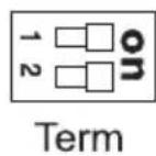
Terminators 100 Ohm, switchable; factory settings on
Internal UPO Port for ISDN Terminals
| Connection types U | P0 with Euro-ISDN protocol (DSS1); 2 B-channels per port, direct connection to a Φ0 telephone or to the Φ0/S0 adapter |
| Range At 0.6 mm diameter: | Screened cable: up to 600 m Unscreened cable: up to 1000 m |
| Supply voltage 40 V +5 % / -15 % | |
| Feeder Max. 4 W | |
External S0 Port for ISDN Network Provider
| Connection type S | 0 basis access as Point-to-Multipoint connection or as a Point-to-Point connection, EURO-ISDN (DSS1), unit is powered locally |
| Range With typical telephone or | network cable (twisted-pair)Max. 150 m for Point-to-Multipoint connectionMax. 1000 m for PTP connection |
| Terminators 100 Ohm, switchable; factory settings on | |
External Analogue Port for Analogue Network Provider
| Range Ca. 800 m at 0.6 mm diameter |
| Type of dialling Tone dialling |
| Reception amplification Configurable: -12 to +12 dB |
| Transmission amplification Configurable: -6 to +6 dB |
External Analogue Port for Analogue Network Provider
| Ringer signal frequency Configurable: 16 / 25 / 50 Hz | |
| CLIP detection Configurable: V.23-FSK / DTMF | |
| Call end detection Configurable: | DTMF code D, line polarity reversal, loop current detection |
| Impedances 270R + (750R || 150 nF) | |
Ethernet Port for Internet and VoIP Terminals as well as PC
| Interface 10/100 Base-T (10/100 Mbit/s, RJ-45 twisted-pair) | |
| VoIP standard SIP according to | RFC 3261 |
| VoIP codecs, internal/external G.711 (default), G.722, G.726, G.729, iLBC | |
| Terminals More than 1 terminal | per internal VoIP channel (overcommitment) |
USB Host for Printer and Storage Medium
| Interface USB (high speed, V2.0) | |
| Storage medium Not included, 1 | GB or more recommended |
SD Card Slot (CPU Board)
| Card SD or SDHC memory card, delivered card 4 GB, Linux partitions (SD card slot until version 4 of the circuit board) | |
| Caution: The memory card contains data which is necessary for the operation of the PBX. Do not remove, mount, or format the memory card. The memory card should only be exchanged in the case of service jobs in accordance with the directives of service staff.eMMC storage (as of version 6) |
Further Information
| Cabinet ABS plastic | |
| Dimensions (W x H x D) | Basic unit COMpact 4000: 334 x 331 x 94.5 mm Modules: 160 x 70 x 25 mm |
| Weight Basic unit COMpact 4000 | 0: approx. 1.6 kg Modules: approx. 100 g (2BRI), approx. 90 g (2FXO) |
| Packaging | Carton (unsuitable as shipping carton) |
Further Information
Security CE
Environmental Notice
Disposal
If you want to dispose of the device, please ensure its professional disposal. Do not put it in the normal household waste.

Dispose of the packaging material properly and in interest of the environmental protection.

Consult your responsible authority for information about the professional and environment-friendly disposal of your device. If you want that we handle the disposal for you, you can send the device at your costs to Auerswald GmbH & Co. KG.
Power Consumption
The power consumption of this PBX is automatically reduced to a minimum. Nevertheless, note the following recommendations for power saving:
- The power consumption of the telephone installation significantly depends on the connected telephones and terminals. When buying terminal devices, make sure that the devices are power-saving, for example, VoIP telephones that comply with the requirements of the basic award criteria of the Blue Angel as described in RAL UZ 150 and standard analogue telephones.
- Remove any storage media used only for data backup from the PBX when they are not in use.
Repair
This PBX has been designed for a long service life. If a part still fails, defective modules (e.g. printed circuit boards) can be repaired. The availability of typical spare parts for this PBX will be ensured for at least five years after production has been stopped.
Declaration of Conformity
This device complies with the basic health, safety and environmental requirements in all relevant EU directives. You will find the Declaration of Conformity on our website.
Conditions of Guarantee
- Auerswald GmbH & Co. KG, Vor den Grashofen 1, 38162 Cremlingen, Germany, grants 24 months Manufacturer's Warranty from the date of purchase, as the manufacturer of this product.
- For you, as a consumer, this means: We guarantee that our devices are error-free when supplied. If a manufacturing error is identified within 24 months of the delivery date we will repair or replace the device free of charge without you, as the consumer, having to provide the usual legally required proof that this fault was present when you received the device. We either use new parts or parts in mint condition for the repair or replacement delivery. Any parts removed from the device become our property and can be destroyed by us.
- In addition to this warranty, you have the unlimited legal right to claim against the supplier on the basis of the terms of the warranty for defects on the basis of the purchase contract. However, in contrast to our Manufacturer's Warranty, the legal warranty for defects only applies to the device's state when sold (handover).
- You can only claim against this warranty if you return the faulty device to Auerswald GmbH & Co. KG or our local general importer or distributor, outside Germany, at your own cost, with a valid proof of purchase (invoice or till receipt). When you return it to us, please provide
Commissioning
a detailed description of the fault that has occurred, and also tell us your telephone number, in case we need to contact you. To prevent shipping damage, provide suitable transport packaging (e.g. original packaging with a secondary shipping box).
5. The Manufacturer's Warranty excludes damage caused by mishandling, operating errors, misuse, external influences, lightning strikes/ power surges, modifications to the product and extensions. Also excluded are wearing parts (e.g. batteries, fuses, rechargeable batteries and memory cards) and damage caused by wearing parts (e.g. if batteries go flat). Shipping damage, consequential damage, and costs arising from down times and travel times are also excluded.
6. The warranty is cancelled if repairs are carried out by unauthorised agents.
Commissioning
Opening the Casing

Warning: Improper handling of the device can cause life-threatening electric shocks and can damage or destroy the PBX.
- Only a qualified electrician may open the casing and perform installation work within an open casing.

Warning: Touching voltage-carrying conductors or telephone connections can cause life-threatening electric shocks. The PBX contains hazardous voltages, even outside of the power supply unit (for instance ringer voltages). Work on active, contact-hazardous parts is only permitted after creating a voltage-free state. Working close to active parts is only permitted if these parts are voltage-free or are protected against direct contact.
- Disconnect the power plug of the PBX and the accessories before instructing a qualified electrician to open the casing. Also disconnect the device from additional power sources (e.g. UPS, if installed).
- Wait at least 3 minutes for the discharge of any capacitor in the device after disconnecting it from the main power supply.
- Only operate the device when the casing is closed.
- Only operate the device mounted on the wall.

Warning: Power surges, which may occur during electrical storms, can cause life-threatening electric shocks, or damage or destroy the PBX.
-
Do not touch the PBX or any devices connected to it during an electrical storm.
-
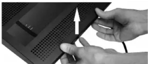
Unlatch both locks simultaneously by compressing each with thumb and index finger.
- Lift the cover and remove it completely from the casing.
Wall-Mounting the PBX

Warning: Touching voltage-carrying conductors or telephone connections can cause life-threatening electric shocks.
- Mount the PBX close of an earth wire (potential compensation bar of the house installation or protective earth conductor). Connect the PBX's earth connection to the earth wire with a connecting cable whose conductor diameter is at least 2.5mm^2

Warning: Liquid entering the casing can cause life-threatening electric shocks or damage or destroy the PBX.
- Only operate the PBX in closed, dry rooms.

Caution: Overheating can damage or destroy the system.
- Note the ambient temperature values indicated in the technical data.
- Make sure that heat produced by the device can be adequately vented into the environment. Do not install the system in a cabinet without adequate air circulation.
- Never cover the air vents of the casing.

Important: Mechanical loads and electro-magnetic fields can impair PBX operation.
- Avoid mechanical loads (e.g. vibrations).
- Avoid the proximity of devices that generate electro-magnetic fields (e. g., radio sets, professional radio equipment, amateur radio equipment, mobile phones, DECT systems, WLAN routers, etc.).
- Protect the PBX from dirt, excessive dust, condensation, caustic liquids, and steam.
Requirements:
- 3 screws and 3 dowels
-
Connections close to the installation site:
-
Freely accessible Schuko socket
- Wall socket or NT provided by the network provider; if the wall socket/NT is relatively far away from the PBX, permanent cabling must first be laid between the devices
-
Grounding conductor (potential compensation bar of the house installation or protective earth conductor)
-
Mark and drill the two upper mounting holes at a distance of 232mm and insert dowels into the holes.

Note: Also note the casing dimensions 334 mm x 331 mm x 94.5 mm. There should be a distance of at least 60 mm between the upper mounting bores and any parts above them. A drilling template can be found on the Internet.
- Screw in the two upper screws far enough so that the screw head is about 5mm away from the wall.
- Mount the PBX on the screws, then slide the PBX on the wall downwards until the screws hit the stopper.
- Place a mark where the third mounting hole is to be drilled into the wall.
- Remove the PBX from the wall.
- Drill the mounting hole and insert a dowel into the hole.
- Mount the PBX on the screws again, then slide the PBX on the wall downwards until the screws hit the stopper.
- Secure the PBX by tightening the third screw.
Connecting the Earthing

Warning: Touching voltage-carrying conductors or telephone connections can cause life-threatening electric shocks. The PBX contains hazardous voltages, even outside of the power supply unit (for instance ringer voltages). Work on active, contact-hazardous parts is only permitted after creating a voltage-free state. Working close to active parts is only permitted if these parts are voltage-free or are protected against direct contact.
- Disconnect terminal devices from the PBX. No terminal devices should be connected during the installation of the earthing. Connected terminals may feed-in currents which might cause electrical shocks.
- Pull out the PBX's power plug. Also disconnect the device from additional power sources (e.g. UPS, if installed).
- Wait at least 3 minutes for the discharge of any capacitor in the device after disconnecting it from the main power supply.
- Only a fixed installation is allowed for the connection of the earthing terminal of the PBX to the potential compensation bar of the house installation or the protective earth conductor. Plug connections are not allowed.
Requirements:
- Screw driver
- Connecting cable with at least 2.5 ~mm^2 conductor cross-section
- Proper earth connection close to the installation site (equipotential bonding rail of the house installation or protective earth conductor)
-
No terminal devices connected
-
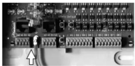
Connect the connecting cable to the potential compensation bar of the house installation or the protective earth conductor.
-
Insert the connecting cable into the casing and connect it to the earth terminal.
Updating or Upgrading the PBX

Warning: Touching voltage-carrying conductors or telephone connections can cause life-threatening electric shocks. The PBX contains hazardous voltages, even outside of the power supply unit (for instance ringer voltages). Work on active, contact-hazardous parts is only permitted after creating a voltage-free state. Working close to active parts is only permitted if these parts are voltage-free or are protected against direct contact.
- Pull out the PBX's power plug. Also disconnect the device from additional power sources (e.g. UPS, if installed).
- Wait at least 3 minutes for the discharge of any capacitor in the device after disconnecting it from the main power supply.

Caution: Electrostatic charges can destroy sensitive components.
- Discharge electrostatic charges from yourself before touching the circuit boards with your hands or any tools. To do this, touch a preferably earthed metal object, such as the PBX's earthing terminal or a computer case.

Important: Before you insert a COMpact 2BRI module, first make the necessary port settings on the module (operating modes and terminators).
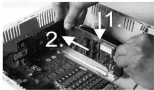
Inserting a Module
- Slide the module into the board guides with the component side pointing to the left.
- Press the module upward until the board lock clicks into place.
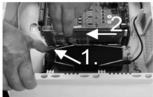
Removing a Module
- Unlatch the board lock, for example with your right thumb.
- Remove the module with your other hand.
Connecting the PC
Requirements:
Available network socket on the PC or in the network of the PC
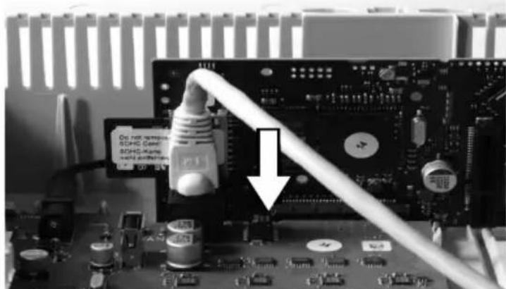
1. Insert one end of the accompanying network cable into the network socket on the PC or in the network of the PC.
2. Insert the other end of the network cable into the Ethernet socket on the COMpact 4000 interface board.
Closing the Casing
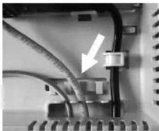
Important: Before closing the casing, secure the Ethernet cable with a cable tie to one of the straps provided for strain relief.
Note: The connections for the first commissioning (connection to a PC/network and, if necessary, connection of a few terminals) must be made before the casing is closed. Alternatively, you can prepare them by laying a connecting cable that leads out of the housing.
Requirements:
-
Cables carefully reinserted into the cable space after installation
-
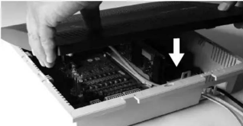
Place the upper edge of the cover onto the top of the casing.
-
Press the lower edge of the cover against the casing until it clicks into place.
Turning on the PBX

Warning: Touching voltage-carrying conductors or telephone connections can cause life-threatening electric shocks.
- Close the casing before you put the PBX into operation.
Requirements:
PBX connected to earthing and casing closed
Connect the PBX to a freely accessible Schuko socket.
The Power and Status LEDs light up several seconds/minutes in red and orange.
When the LEDs light up in green, the PBX is ready for operation.
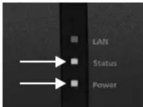

Note: If the Power LED remains continuously lit in red, an error has occurred. Please contact your dealer or the manufacturer directly.
First Setup

Warning: Incomplete or incorrect configuration can be hazardous to people, if for example emergency calls cannot be performed.
- The configuration of the product is made via an integrated web server whose pages are called via web browser. The user interface of the web server (Configuration Manager) is available in English and German. If you are not familiar with these
languages and the technical terms, please consult a specialist who is linguistically and professionally qualified.
Information about the Network Connection
Configuring the PBX using a PC is done using the configuration manager integrated in the PBX. This can be accessed via the IP address of the PBX. The IP address to be used depends on your connection and network environment.
- If the PBX is not connected to a router but is connected directly to a single PC which receives its IP address automatically (default setting on Windows and Mac OS X), you can access the PBX via the permanent IP address 169.254.1.240 from the APIA address range.
-
If the PBX is connected to a router that works as a DHCP server and allocates IP addresses to the devices connected (default setting on most routers), you can access the PBX via two IP addresses:
-
Via the permanent IP address 169.254.1.240 from the APIPA address range.
- Via the IP address allocated by the DHCP server.

Note: If the permanent IP address from the APIA address range is not working, you will first have to learn the IP address allocated by the DHCP server. You have the following options:
- If the UPnP service is installed and activated on the PC (e. g. on Windows 8), the PBX can be found and selected in the network environment as "COMpact 4000" device.
- You can use a network scanner (f. e. Angry IP Scanner).
- You can connect a CLIP-capable analogue telephone and query the IP address by entering the character string # # 8^*941# and then hanging up the receiver.

Important: If you wish to operate the PBX in a network where IP addresses are allocated permanently, you must first connect a CLIP-capable analogue telephone and adapt the IP configuration of the PBX for operation in the network (see next chapter).
Configuring a Permanent IP Address in the PBX
- Pick up the receiver of an internal telephone.
- In sequence, dial ##8, the 6-digit admin PIN (none in the factory settings) and 9300#.
You will hear the confirmation tone (pulsating tone).
The DHCP client function is disabled in the PBX.
- Hang up the receiver and then pick it up again.
- In sequence, dial ##8, the 6-digit admin PIN (none in the factory settings), 931, the 12-digit IP address (e.g. for 192.168.2.10: 192168002010) and #.
You will hear the confirmation tone (pulsating tone).
The entered IP address has been configured in the PBX (for subnet mask 255.255.255.0).
- Hang up the receiver.
Opening the Configuration Manager
Requirements:
PC with a min. screen resolution of 1024 x 768
- Recommended Browser: Mozilla Firefox (current version), Google Chrome (current version)
- Enter the IP address of the PBX in the address field of the browser. Example for entering the permanent IP address: https://169.254.1.240. Since the PBX forces an HTTPS connection, your browser will provide a safety warning (because of the missing safety certificate).
- If necessary, transmit the safety certificate to your working environment (user and browser profile).
- Click with wizard (recommended).
- Use the configuration wizard to carry out the system activation and configure the basic settings.
Telephoning
Outgoing Calls/Exchange Line Request
When dialling phone numbers, the exchange line request type configured for the subscriber must be noted. The PBX distinguishes three types of exchange line requests:
Automatic exchange line request (factory setting): Neither for the internal nor for the external number a prefix is required (exception: ** for targeted VoIP access). The PBX automatically distinguishes between internal and external numbers with the adjustment of the dialled phone number and the internal numbering plan:
- If the phone number is contained in the telephone numbering list, the PBX establishes an internal connection.
- If the phone number is not contained in the telephone numbering list the PBX establishes an external connection.
Internal telephone: The user has to dial an external number with preceding exchange line access number.
Direct exchange line telephone: For an external number no prefix is required. However, the user has to dial an internal number with preceding **.

Note: The behaviour of COMfortel 1400 IP/2600 IP/3200/3500/3600 IP telephones when numbers are being dialled depends on the set default account (see manual of the phone). For COMfortel 1400 IP/2600 IP/3600 IP telephones as of firmware version 2.4, the default account can be taken over from the PBX if the telephone is a system telephone and is thus set dependent on the type of exchange line request.

Note: To avoid conflicts between 3 or 4 digit phone numbers of the local area network and the internal numbering plan, phone numbers of the local area network should always be dialled with local area code.

Note: Also when the entered phone number correspond with the internal telephone numbering plan, the PBX waits up to 4 seconds for whether additional digits for an external number are being entered, before it dials the internal phone number. To avoid waiting time, you can subsequently enter #. The PBX therefore recognises the input as finished and instantly starts dialling.
Emergency Calls
The emergency numbers set up on the PBX are used for emergency calls. These calls are handled in a special way.

Note: One of the basic settings is the setting of the country where the PBX is located. By this setting the public emergency numbers of the selected country are automatically entered in the configuration.
Emergency calls can be made without dialling an exchange line access number that is necessary for other calls (factory setting). This has the benefit that even people who do not know how to use exchange line access numbers can make emergency calls.
If the emergency call priority switch is enabled (factory setting), emergency calls have priority over other calls. If necessary, a call can be interrupted to enable an emergency call to be made.
A system telephone can also be used to make emergency calls if the screen lock is switched on (optional, see telephone's instructions).
Installation

Warning: Power surges, which can occur during electrical storms, can cause life-threatening electric shocks and can damage or destroy the PBX.
- Do not touch the PBX or any devices connected to it during an electrical storm.
- Hire a qualified electrician to lay the cables within the building – including the cable to the door terminal.
- Do not use the a/b ports to connect remote extensions.

Warning: Touching voltage-carrying conductors or telephone connections can cause life-threatening electric shocks. The PBX contains hazardous voltages, even outside the power supply unit (for instance ringer voltages). Work on active, contact-hazardous parts is only permitted after creating a voltage-free state. Working close to active parts is only permitted if these parts are voltage-free or are protected against direct contact.
- Pull out the PBX's power plug before instructing a qualified electrician to open the casing, to install the expansion modules, or to switch or connect equipment. Also disconnect the device from additional power sources (e.g. UPS, if installed).
- Wait at least 3 minutes for the discharge of any capacitor in the device after disconnecting it from the main power supply.
Installation

Important: Improper use can cause, for example, functional restrictions or interference, the destruction of the device or, in a worst-case scenario, personal injury.
Only connect equipment that is compatible with the proper use of the PBX.

Installation Instructions
The PBX is intended to be operated in closed rooms. In addition, all of the devices connected to the system must be located inside the building.
The PBX enables you to connect some devices directly, inasmuch as they are close enough to the PBX. The distance depends on the length of the equipment connection cables up to a maximum of 10m .
If no suitable connection sockets are available or are too far away, you must lay the installation cable permanently. Use installation cable (e.g. J-Y(St)Y 2x2x0.6) with the following characteristics:
- Unscreened; however: screened for unfavourable conditions, for example, near a strong transmitter or an electrical power line
- only for ISDN: preferably star quad stranding
ISDN: When assigning the individual wires, orientate yourself with the identifiers subsequently listed or refer to VDE 0815 when identifiers deviate.
| Cable with Two Twin Wires | Cable with Star Quad | ||
| Physical circuit/pair 1 | a1 | red without ring | |
| b1 | black single rings, 17 mm spacing | ||
| Physical circuit/pair 2 | a2 | white double rings, 34 mm spacing | |
| b2 | yellow double rings, 17 mm spacing |
Analogue/ U_P0 : Prevent interferences. Avoid laying long lengths of parallel lines, especially next to the mains. Twist the pairs.
Accessories and service parts can be bought at specialised stores.
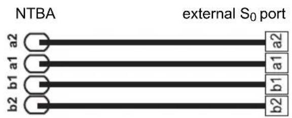
Network Provider at the External S_0 Port
Connection possibilities:
- NTBA
Digital GSM gateway - Router with internal S 0 port
VoIP/ISDN adapter
Requirements:
- Enabled operating mode "S 0 external" on the S_0 port in question
Terminators enabled at both ends of the connection - in the NTBA and in the PBX on the external S_0 port in question
operating mode S_0 external" terminators enabled
If the NTBA only has a slight distance to the PBX, make a direct connection via the RJ45 socket (cable in the scope of delivery).
If the NTBA has a greater distance to the PBX, then a cable must be laid fixed on the terminal clamps of the external S_0 port.
Network Provider at the External Analogue Port

Warning: Voltages that run through the connection socket of the network provider can cause life-threatening electric shocks.
- Do not connect the PBX until the casing on the connection socket of the network provider is closed again.
Connection possibilities:
- Public analogue telephone network across Europe
- Analogue GSM gateway
If the analogue connection has a greater distance to the PBX, a cable with a wall socket at the terminal clamps of the external analogue port must be laid fixed. Connect the devices with the RJ-11/RJ-11 connection cable included in the scope of delivery. Within Germany, you additionally require the RJ-11/TAE-F adapter.
external analogue port
RJ-11 wall socket
Internet and VoIP Terminals as well as PC at the Ethernet Port
Connection possibilities:
PC
- Internet (VoIP accounts with one or more VoIP phone numbers similar to the PMTP connection on ISDN and VoIP accounts with an extensions block similar to the PBX connection under ISDN, based on the SIP-DDI feature (also known as SIP trunking)
COMfortel 1400 IP/2600 IP/3600 IP system telephones
COMfortel 3200/3500 system telephones (firmware version 1.8E or later)
- IP DECT single- and multicell servers COMfortel WS-400 IP and COMfortel WS-650 IP for COMfortel M-100, COMfortel M-200/210 and COMfortel M-300/310 DECT handsets.
Installation
- Standard VoIP telephone (SIP), e. g. COMfortel 1200 IP
Softphones (SIP) - IP switch relays (e.g. NETIO 230B, WebRelay (identical to Keil), Energenie EG-PM2-Lan, Philips hue)
- IP door terminals (e.g. Telecom Behnke Serie 20 IP, Baudisch SIP door terminal Maxi, TCS FBI 6101, ELCOM LBM-300)
Requirements:
- For Internet access: Broadband Internet connection (e.g. DSL router, TV cable router)
- Existing network (LAN) or single switch (for VoIP terminals) with a data transmission rate of 100 Mbit/s

Note: For VoIP data communication in combination with the transmission of limited amounts of data, a data transmission rate in the LAN of 10 Mbps is sufficient under certain circumstances. For VoIP data communication in combination with the transmission of large amounts of data (e.g. downloads), we recommend upgrading to a data transmission rate of 100 Mbps. For this purpose, replace not only all of the active network components (e.g. switch and router), but also all of the passive network components (e.g. cables and wall sockets). For a reliable support of 100 Mbps, you need cables and wall sockets of at least Category 5 (CAT 5).

Note: When using a switch with PoE function, a separate power supply (e. g. via a power plug) is not required for connected VoIP telephones, always provided they support PoE.
- For the use of DiffServ for prioritising language packages: DiffServ support of all active network components available and enabled
- NAT traversal should be carried out either by the PBX or by a well-functioning SIP-aware router

Note: If the router is not SIP aware, several of the ports on the router necessary for VoIP data communication must be enabled (RTP port and SIP UDP ports) (port forwarding). A list of the ports used in the PBX can be found in the Configuration Manager of the PBX under Overviews > Ports.

Caution: Opening a port on the NAT router is a security risk.
- Take additional protection measures.

Important: If you want to integrate the PBX into an existing network, contact the responsible system administrator. Making changes to an existing network can cause considerable malfunctions.
Analogue Terminals at the Analogue Port
Connection possibilities:
- Analogue telephones
- Analogue fax devices
- Analogue answering machine
- Modems
a/b audioboxes - a/b door terminals (e.g. TFS-Dialog 200/300/400, TFS-Universal plus, TSA a/b)
A wall socket (RJ-11 or, within Germany, TAE) must be connected via a fixed laid cable with the terminal clamps of the internal analogue port.
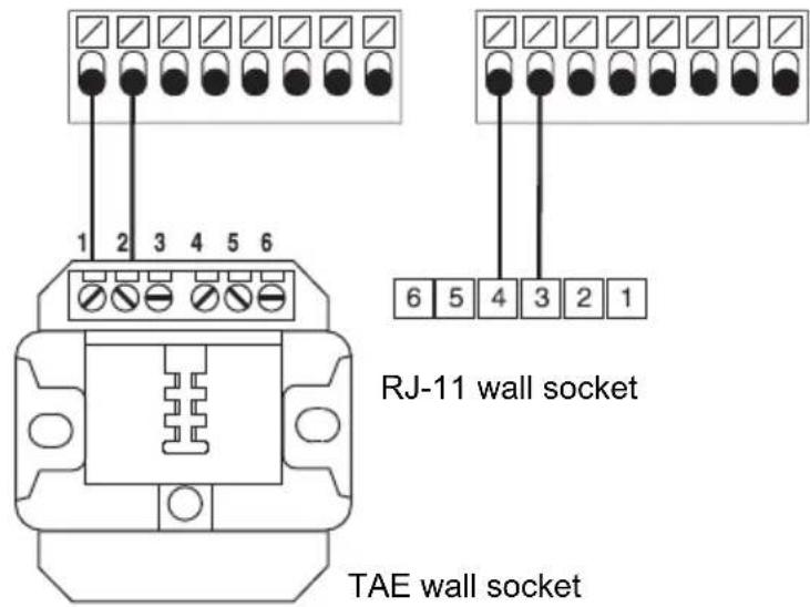
internal analogue ports
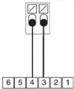
ISDN Terminals at the Internal S_0 Port
Connection possibilities:
- System telephones COMfortel 1200/1400/1600/2600 (firmware version 1.6A or later)
ISDN telephones in accordance with the Euro ISDN Standard (DSS1) - ISDN PC controllers in accordance with the Euro ISDN Standard (DSS1)

Important: For COMfortel 1400/2600 with answering machine: In order to ensure that the full scope of functions is available, you should connect only 1 telephone per port.
Requirements:
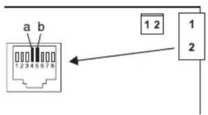
- Enabled operating mode "S 0 internal" at the S_0 port in question
- Enabled terminators in the PBX at the internal S 0 port in question (exception: bus wiring in two directions)
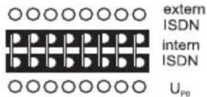
operating mode "S0 internal"
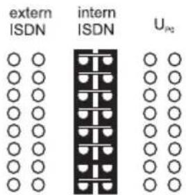
terminators enabled
Installation
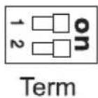
If PBX and terminal have a short distance to each other, make the connection with an ISDN cable (max. 10m ) at the RJ-45 sockets of the internal port.
If the distance between PBX and terminal is greater, lay the lines fixed at the terminal clamps of the internal S_0 port.
ISDN Terminal at the Internal U_P0 Port
Connection possibilities:
- System telephones COMfortel 1200/1400/1600/2600 (firmware version 1.6A or later)
ISDN telephones in accordance with the Euro ISDN Standard (DSS1) - ISDN PC controllers in accordance with the Euro ISDN Standard (DSS1)
Requirements:
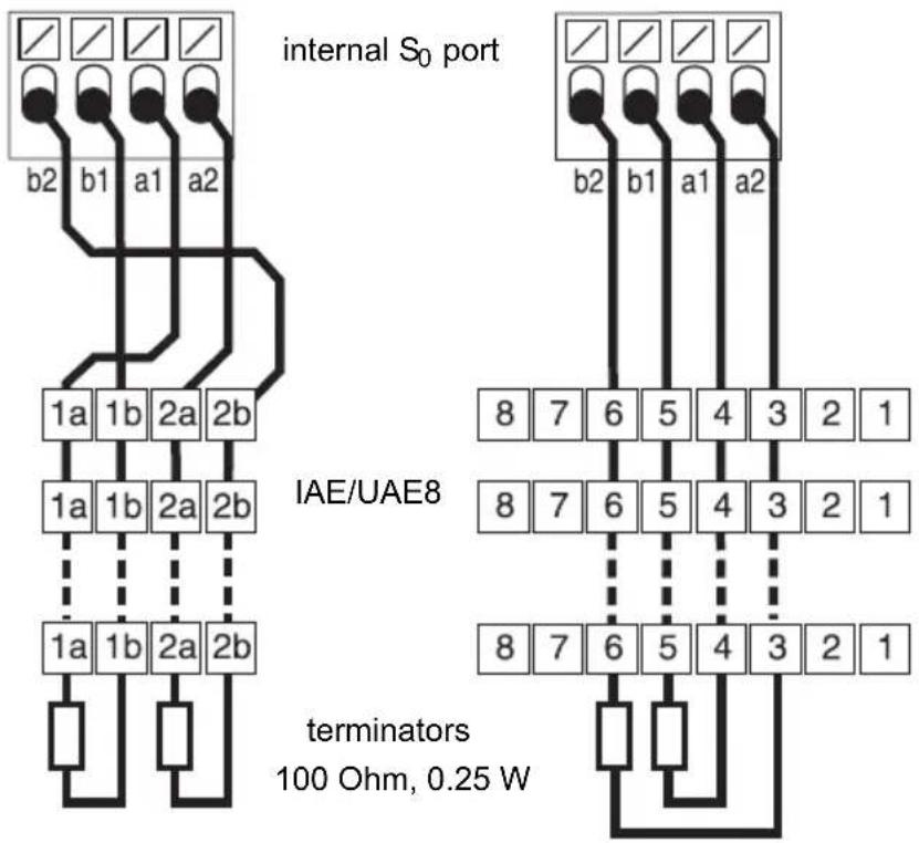
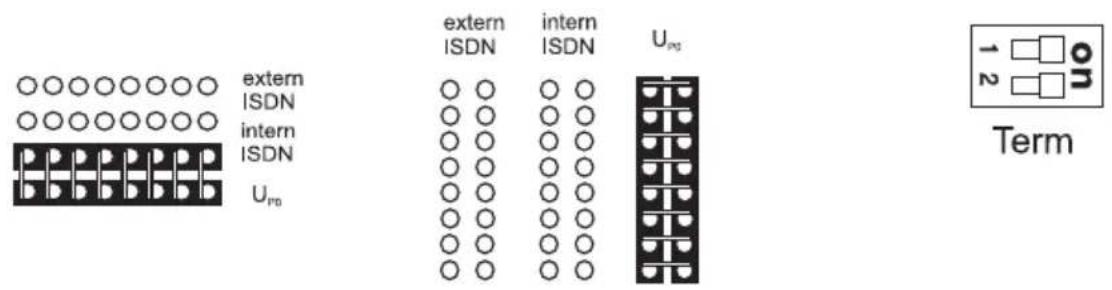
- Enabled operating mode "U P0internal " at the UP0 port in question
- Enabled terminators in the PBX at the internal U _P0 port in question
operating mode "UPO internal" terminators enabled
If the terminals and the PBX have a short distance to each other, connect a single COMfortel 1200/1400/1600/2600 system telephone directly to the RJ-45 socket of the internal UP0 port. For all other ISDN terminals or two system telephones per port you require a UP0 / S_0 Adapter.
If the distance between PBX and terminal is greater, lay the lines fixed at the terminal clamps of the internal U_P0 port.
Caution: Terminals integrated in the wall sockets are destroyed and can damage the device.
- Contrary to the S_0 port, do not equip a line at the U_P0 port with terminals. These are already integrated in the terminals (COMfortel 1200/1400/1600/2600 or U_P0/S_0 Adapter.
- Remove terminals which have already been integrated in the wall sockets for use at the _P0 port.
Note: You do not need an ISDN wall socket if you use a UP_0 / S_0 Adapter. The UP_0 / S_0 Adapter can be mounted on the wall or it can be connected to the PBX via the two screw terminals on the back.
Espanol
TpoTIOoIaVaaBaoiOn TnAePwviKou Kevtpou. 89
Spcifications techniques. 104