RHU131C - Crimping tool Cembre - Free user manual and instructions
Find the device manual for free RHU131C Cembre in PDF.

User questions about RHU131C Cembre
0 question about this device. Answer the ones you know or ask your own.
Ask a new question about this device
Download the instructions for your Crimping tool in PDF format for free! Find your manual RHU131C - Cembre and take your electronic device back in hand. On this page are published all the documents necessary for the use of your device. RHU131C by Cembre.
USER MANUAL RHU131C Cembre
natural_image
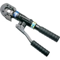
Close-up of a mechanical crimping tool with warning labels and red connectors (no readable text or symbols)ENGLISH
FRANÇAIS
DEUTSCH
ESPAÑOL
ITALIANO
This manual is the property of Cembre: any reproduction is forbidden without written permission.
Suitable for compression of electrical connectors on conductors up to 400 mm^2 (800 MCM) and aluminium conductors up to 300 mm^2 (600 MCM).
- Crimping force: 130 kN (14.6 sh ton)
- Max operating pressure: 700 bar (10,000 psi)
- Oil necessary (displacement): 47 cm ^3 (2.9 cu. in.)
- Dimensions: length 245 mm (9.65 in.)
width....89 mm (3.5 in.)
- Weight: 3,7 kg (8.16 lbs)
2. APPLICATION RANGE
2.1) The RHU131-C head is supplied with the AU130-C adaptor, which will accept semicircular slotted dies common to Cembre 130 kN (14.6 sh ton) tooling suitable for:
- Indentation on copper conductors.
- Circular compression on copper conductors.
- Hexagonal compression on copper, almelec or aluminium conductors.
2.2) With the upper adaptor AU130-... and lower adaptor AC130-P, the RHU131 or RHU131-C head will accept:
- Pre-rounding dies UP130-... (used for converting aluminium sectoral conductor to a compact, round section).
- Containing dies (MV, MVC, MVM, MUA series) and the indentors PS130-.../E (to crimp connectors on aluminium cables using the deep indent crimping system).
3. INSTRUCTIONS FOR USE (Ref. to Fig. 2 and 3)
These instructions generally refer to the RHU131-C head, but are also suitable for the RHU131 head, fitted with AU130-... and AC130-P adaptors (regardless of die selected).
3.1) Setting
The head is equipped with a "self-lock" quick male coupler suitable for connection to a hydraulic, pneumatic or electrical pump from the Cembre range.
* The RHU131-C head is the RHU131 head fitted with adaptor AU130-C (Ref. to Fig. 2).
3.2) Die advancement
- Insert the conductor into the connector.
- Locate the connector between the dies at the desired crimp position.
- Operate the pump until the dies touch each other.

Never pressurize the head without inserting the dies as this could cause damage to the head and the ram.

Make sure that dies are exactly positioned on the area to be crimped; otherwise re-open is following instructions as per § 3.4 and re-position the connector.
3.3) Crimping
Operate the pump to advance the main ram until the dies are fully closed.
It is recommended to continue pumping until the maximum pressure valve is activated and a "click" is heard.
3.4) Dies opening
Fully release the oil pressure from the pump, to retract the ram and release the crimped connector.
4. CRIMPING OF CONNECTORS ON COPPER CABLES (Ref. to Fig. 2 and 3)
4.1) Connector crimping
- Fit adaptor AU130-C (see § 4.2).
- Select the appropriate die set for the connector.
- Insert die set into upper and lower die holders (see § 4.3).
- Insert the conductor in the connector.
- Position the connector between the dies and ensure the correct location of the crimp.
- To crimp connector continue as § 3.2.
4.2) Adaptor assembly
Insert the AU130-C (90) adaptor in the guides on the U-fork (14) until securely located, with the grooves on the adaptor corresponding to the locators (15) on the U-fork head (14).
Remove the adaptor by pushing it off the locators and sliding it from the head.
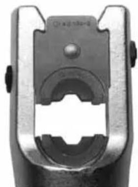
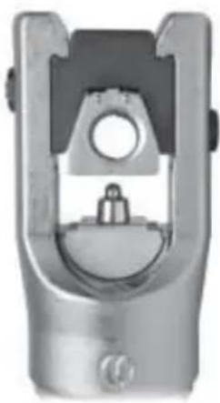
4.3) Dies assembly
4.3.1) Press release button (86) and insert the upper die (88) into the AU130-C adaptor (90) until secured by the die retaining pin (87).
To remove the upper die, press the release button (86) and slide the die from the adaptor (90).
4.3.2) Press the release pin (12) and insert the lower die (89) into the seat on the ram (09) until secured by the pin (11). To remove the die press the release pin (12) and slide the die from the ram. To facilitate this operation an advancement of 3-4 mm (0.11 - 0.16 in.) of the ram (09) is suggested.
5. CRIMPING OF CONNECTORS ON ALUMINIUM CABLES (Ref. to Fig. 4, and 5)
5.1) Pre-rounding conductor (for sectoral cables)
- From the table (Fig. 7, page 30) select the adaptors and pre-rounding dies for the appropriate conductor size.
- Insert the upper adaptor AU130-... and lower adaptor AC130-P into the head (see § 5.3).
- Insert the pre-rounding die (94) into the AC130-P adaptor (see § 5.4).
- Position the conductor into the pre-rounding die (95) and locate the pre-rounding die (95) in the adaptor AU130-... (see § 5.4). Ensure that the pre-rounding die is correctly located in the adaptor with its upper slot in line with the internal adaptor pins.
- Operate the pump until the dies are fully closed.
Release the hydraulic pressure (see § 3.4) and remove the compacted round conductor.
5.2) Connector crimping
- Remove the pre-rounding dies and the adaptor AC130-P from the head (see § 5.4).
- From the table (Fig. 7, page 30) select the containing die and indentor recommended for the conductor size.
- Insert the indentor PS130.../E into the ram (09) (see § 5.4).
- Insert conductor into the connector; locate the connector into the containing die; locate the containing die in the adaptor (see § 5.4).
Commence indent crimping from the barrel end for both splices and terminals, following the sequence shown below. - For every operation ensure the die is correctly located in the adaptor with its upper slots in line with the internal adaptor pins.
- Each indenting operation is completed when indentor and die are fully closed; it is recommended to continue pumping until the maximum pressure valve is activated and a "click" is heard (see § 3.3).
INDENTING SEQUENCE
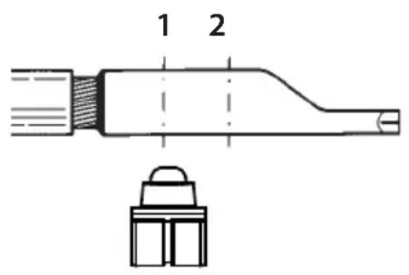
text_image
1 2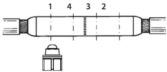
text_image
1 4 3 25.3) Adaptor fitting and removal
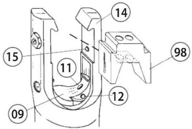
- Insert the upper adaptor AU130-... (98) into the U-fork head (14) until secured by the locators (15). To remove the adaptor from the U-fork head, push the adaptor from the locators and slide out.
- To insert the adaptor AC130-P(91), press the die release pin (12).
- Insert the upper adaptor AU130-... (98) into the U-fork head (14) until secured by the locators (15). To remove the adaptor from the U-fork head, push the adaptor from the locators and slide out. - To insert the adaptor AC130-P(91), press the die release pin (12).
Insert the adaptor into the seat of the ram (09), until secured by the retaining pin (11).
To facilitate this operation, an advancement of 3 ÷ 4 mm (0.11 - 0.16 in.) of the ram (09) is suggested.
To remove the adaptor, press the die release pin (12) and slide the adaptor from the ram (09).
5.4) Dies, indentors, pre-rounding dies - fitting and removal (Ref. to Fig. 5)
- The containing die (96) and upper pre-rounding die (95): are located in the adaptor AU130-... (98) by grooves in the upper face.
- The lower pre-rounding die (94): is inserted or removed from the adaptor AC130-P (91), by pulling the release button (92).
- The indentor PS130.../E (93): is inserted into the seat on the ram (09) (see § 4.3.2).
6. MAINTENANCE
The head is robust and requires very little daily maintenance.
Compliance with the following points should help to maintain the optimum performance of the tool.
6.1) Accurate cleaning
Dust, sand and dirt are a danger for any hydraulic device.
Avoid putting the head on muddy or dusty ground. Any dirt particles may score the ram and create oil leaks.
Every day, after use, the head must be cleaned with a clean cloth, taking care to remove any residual particles, especially around the moving parts.
6.2) Replacement of the automatic coupler
Use a 22 mm spanner to unscrew the old coupler:
- Remove the obsolete coupler.
- Carefully clean the thread to remove the old sealant.
- Apply Teflon tape to the thread.
- Fit the new automatic coupler and tighten to 30 Nm (22 lbf ft).

The oil pressure in the head must always be completely released before disconnecting the oil from the hose.
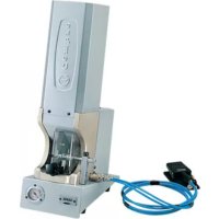
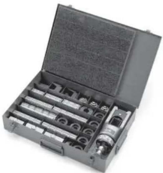
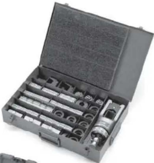
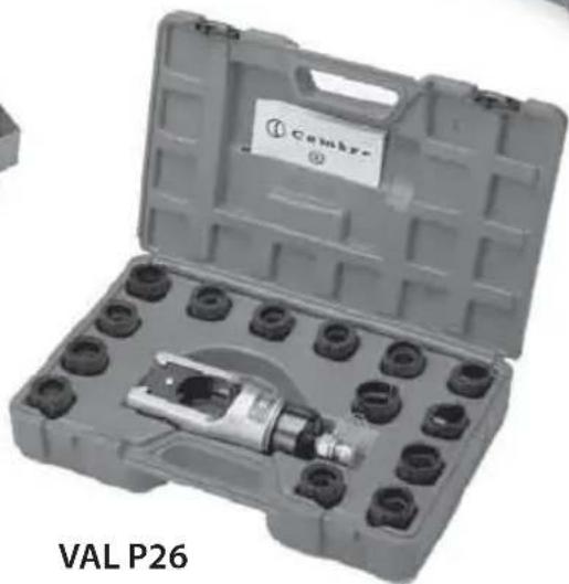
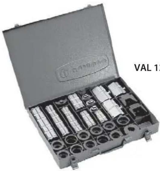
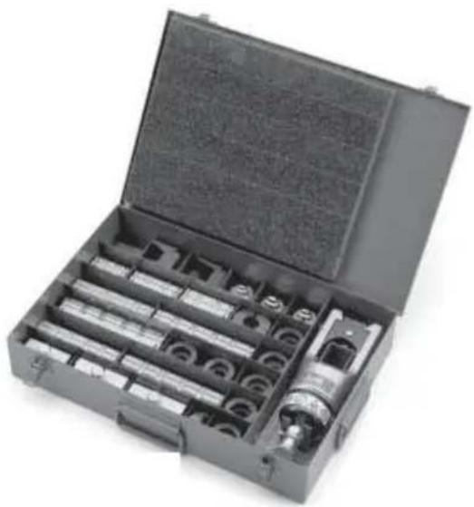
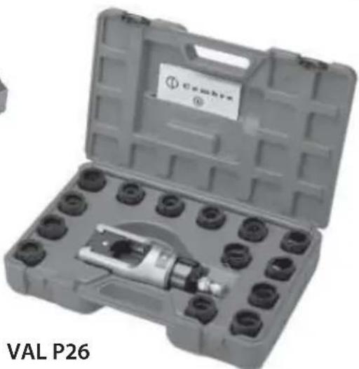
6.3) Storage (Ref. to Fig. 1)
When not in use, the head should be stored and transported in it's case to prevent damage. Following cases are available:
- VAL P26 plastic case; size 445x290x115 mm (17.5x11.4x4.5 in.); weight 1,2 kg (2.65 lbs), for storage of the head and 14 sets of semi-circular slotted dies.
- VAL 130-U steel case; size 450x305x80 mm (17.7x12x3.15 in.); weight 5 kg (11 lbs), for storage of the head, semi-circular slotted dies and accessories for crimping aluminium connectors.
- VAL 130 steel case; size 360x280x48 mm (14.17x11x1.89 in.); weight 3 kg (6.62 lbs), for storage of the accessories for crimping aluminium connectors.
7. RETURN TO Cembre FOR OVERHAUL
In the case of a breakdown contact our Area Agent who will advise you on the problem and give you the necessary instructions on how to dispatch the tool to our nearest service Centre; if possible, attach a copy of the Test Certificate supplied by Cembre together with the tool or fill in and attach the form available in the "ASSISTANCE" section of the Cembre website.
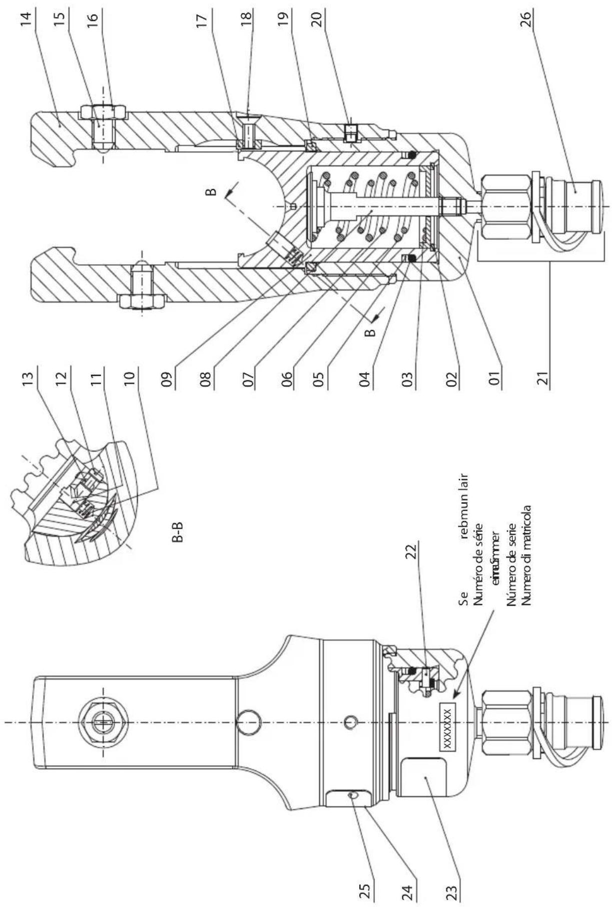
8. PARTS LIST (Ref. to Fig. 6)
| Code N° | Item DE | SCRIPTION Qty | |
| 6120123 | 01 | CYLINDER | 1 |
| 6700250 | ● 02 | ∅ 36 CIRCLIP | 1 |
| 6170140 | ● 03 | SPRING COVER | 1 |
| 6360420 | ● ★04 | O-RING | 1 |
| 6040320 | ● ★05 | BACK-UP RING | 1 |
| 6520620 | ● 06 | RAM RETURN OUTER SPRING | 1 |
| 6520610 | ● 07 | RAM RETURN INNER SPRING | 1 |
| 6300040 | ● 08 | RAM SPRING GUIDE | 1 |
| 6620315 | ● 09 | RAM | 1 |
| 6522006 | ● 10 | PIN SPRING | 1 |
| 6620320 | ● 11 | DIE RAM RETAINER PIN | 1 |
| 6620445 | ● 12 | DIE RAM RELEASE PIN | 1 |
| 6760040 | ● 13 | ∅ 3x8 SPRING PIN | 1 |
| 6280025 | ● 14 | U-FORK HEAD | 1 |
| Code N° | Item DE | SCRIPTION Qty | |
| 6340630 | ▲ 15 | M10 DOWEL | 2 |
| 6180800 | ▲ 16 | M10 NUT | 2 |
| 6100035 | 17 | KEY | 1 |
| 6900250 | 18 | M5x14 SCREW | 1 |
| 6362035 | ★ 19 | SEAL | 1 |
| 6340082 | 20 | M6x8 GRUB SCREW | 1 |
| 6060120 | 21 | COUPLER Q14-MS | 1 |
| 6760040 | ● 22 | ∅ 3x8 SPRING PIN | 1 |
| 6232006 | 23 | LABEL (TG. 0356) | 1 |
| 6232061 | 24 | METAL LABEL (TG. 0261) | 1 |
| 6650118 | 25 | ∅ 2,5x3,5 RIVET | 2 |
| 6800186 | 26 | PROTECTION CAP | 1 |
| 6620316 | ● | COMPLETE RAM | |
| 6280026 | ▲ | COMPLETE FORK |
The items marked (★) are those Cembre recommend replacing if the head is disassembled. These items are supplied on request in the "RHU131 Spare Parts Package (Cod. 6000075)".
The guarantee is void if parts used are not Cembre original spares.
When ordering spare parts always specify the following:
- code number of item
- name of item
- type of head
- head serial number
natural_image
Open mechanical tool kit with multiple cylindrical components and a cylindrical housing (no visible text or labels)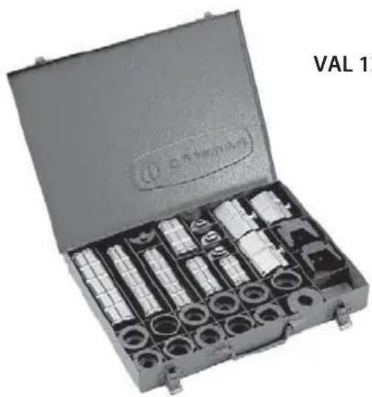
natural_image
Open mechanical tool kit with multiple cylindrical components and a labeled open lid (no visible text or symbols on main subject)VAL 130
FIG. 1 STORAGE CASES
VAL 130-U

natural_image
Open industrial tool kit with a metal clamp and circular base (no visible text or symbols)VAL P26
1. CARACTERISTIQUES GENERALES
natural_image
Open mechanical tool kit with multiple cylindrical components and a labeled part 'VAL 130' (no other text or symbols visible)FIG. 1 RANGEMENT
natural_image
Open mechanical tool kit with multiple cylindrical components and a cylindrical housing (no visible text or labels)VAL 130-U
natural_image
Open industrial tool kit labeled 'VAL P26' with a metal component and a tag (no readable text beyond label)natural_image
Open mechanical tool kit with multiple cylindrical components and a labeled part 'VAL 130' (no other text or symbols visible)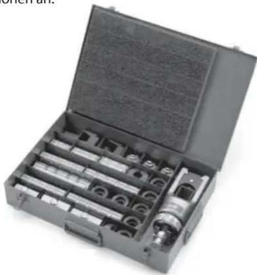
natural_image
Open mechanical tool kit with multiple cylindrical components and a metallic fitting (no visible text or symbols)VAL 130-U
BILD 1 LAGERUNG
VAL P26
1. CARACTERISTICAS GENERALES
natural_image
Open mechanical tool kit with multiple cylindrical components and a central shaft (no visible text or labels)VAL 130-U
natural_image
Open mechanical tool case with multiple cylindrical components and a labeled part 'VAL 1' (no readable text on main subject)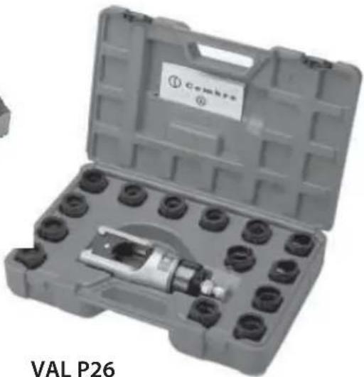
natural_image
Open industrial tool kit with a metal component and labeled part (no readable text or symbols on the main subject)natural_image
Open mechanical tool kit with multiple cylindrical components and a labeled part 'VAL 13' (no readable text on main subject)VAL 130
natural_image
Open mechanical tool kit with multiple cylindrical components and a cylindrical housing (no visible text or labels)VAL 130-U
natural_image
Open industrial tool kit with multiple bolts and a central mechanical component (no visible text or symbols)FIG. 1 CUSTODIE
FIG. 2
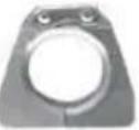
ACCESSORIES
ACCESSOIRES
ZUBEHÖR
ACCESORIOS
ACCESSORI
natural_image
Close-up of a mechanical clamp or bracket component (no visible text or symbols)| AU 130-C Adaptor | Adaptateur AU 130-C | Adapter AU 130-C | Adaptador AU 130-C | Adattatore AU 130-C |
| Nest and Indent dies | Matrice et Poinçon | Matrize und Stempel | Matriz y punzón | Matrice e punzone |
| Circular dies | Matrices circulaires | Rundpress- einsätze | Matrices semicirculares | Matrici semicircolari |
| Hexagonal dies | Matrices hexagonales | Sechskant Presseinsätze | Matrices hexagonales | Matrici esagonali |
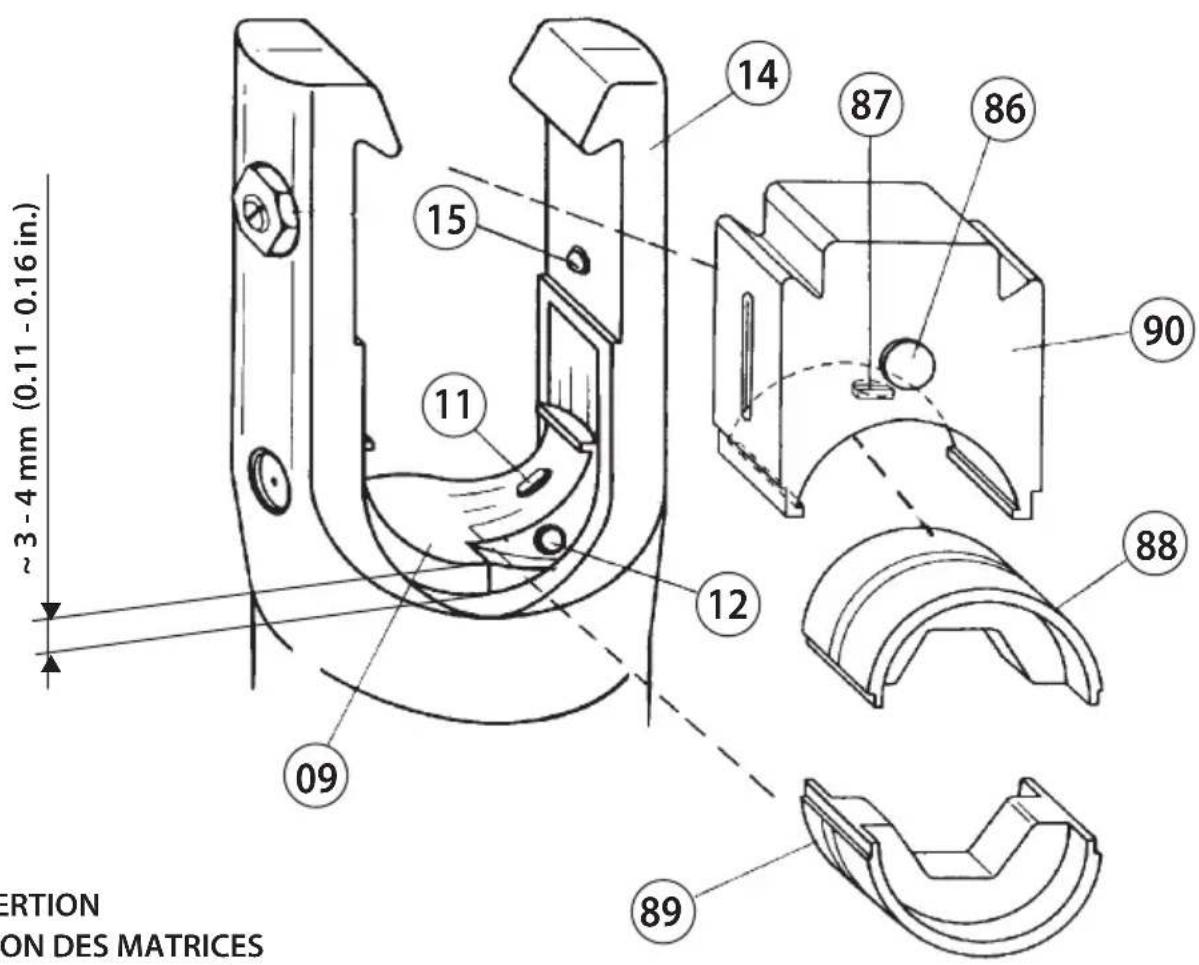
text_image
3-4 mm (0.11 - 0.16 in.) ERTION ON DES MATRICES 15 14 87 86 90 11 12 88 09 89FIG. 3 DIE INSERTION INSERTION DES MATRICES EINSETZEN PRESSEINSÄTZE INSERCION DE LAS MATRICES INSERIMENTO MATRICI
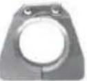
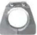
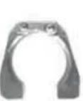
FIG. 4
ACCESSORIES
ACCESSOIRES
ZUBEHÖR
ACCESORIOS
ACCESSORI
natural_image
Metal mechanical component with internal cavities and mounting holes (no visible text or symbols)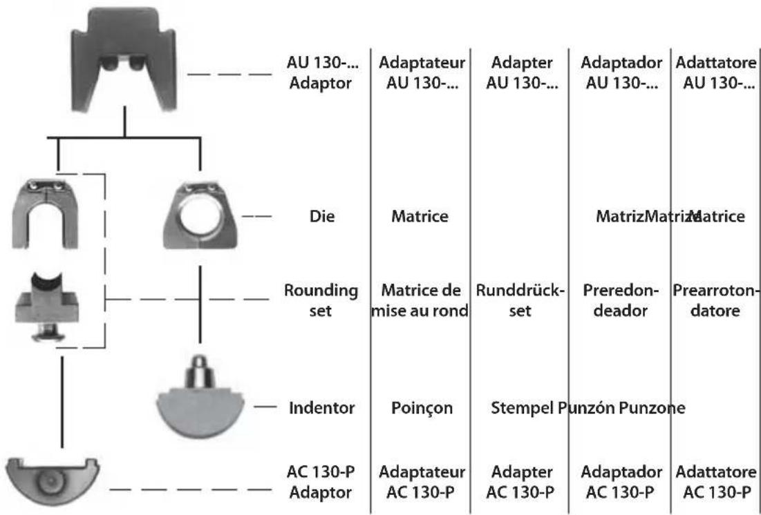
flowchart
graph TD
    A["Adaptor"] --> B["AU 130-... Adaptor"]
    A --> C["Die"]
    A --> D["Rounding set"]
    A --> E["Indentor"]
    A --> F["AC 130-P Adaptor"]

    G["Adaptateur AU 130-..."] --> H["Adapter AU 130-..."]
    I["Matrice"] --> J["Runddrückset"]
    K["Poinçon"] --> L["Stempel Punzone"]

    M["Adaptador AU 130-..."] --> N["MatrizMatriz Matrice"]
    O["Preredon-deador"] --> P["Prearroton-datore"]
text_image
15 11 12 14 98 09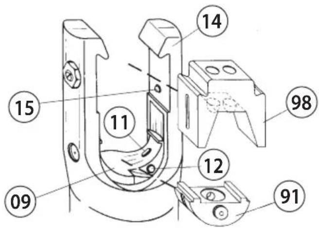
text_image
Technical diagram of a mechanical device with numbered components for identification
text_image
G 5 09 96 93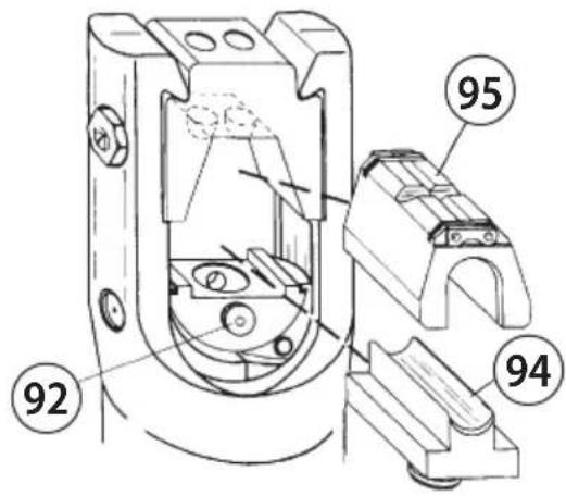
text_image
92 94 95FIG. 5
DIE INSERTION - INSERTION DES MATRICES - EINSETZEN PRESSEINSÄTZE - INSERCION DE LAS MATRICES - INSERIMENTO MATRICI
text_image
Technical schematic diagram of a mechanical device with numbered components and labeled parts in FrenchFIG. 6 LONGITUDINAL SECTION - COUPE LONGITUDINALE - SCHNITTZEICHNUNG - SECCION LONGITUDINAL - SEZIONE LONGITUDINALE
FIG. 7 GUIDE TO THE SELECTION OF ACCESSORIES - GUIDE POUR LA SELECTION DES ACCESSOIRES - ZUBEHÖR FÜR DIE TIEFNUTKERBUNG - GUIA PARA LA ELECCIÓN DE ACCESORIOS -
GUIDA PER LA SCELTA DEGLI ACCESSORI
Conductor sectionSection conducéurLeiter OuerschnittSección cableSezione cavc (mm^2) 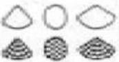 AluminiumAluminioAlluminio AluminiumAluminioAlluminio | Upper adaptorAdaptateur superieurWerkzeughalterAdaptador superiorAdattatore superiore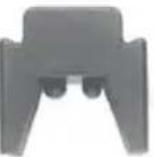 | ...ower adaptorAdaptateur inférieurHalterAdaptador inferiorAdattatore inferiore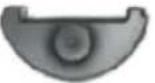 | Pre-rounding dieMatr. de mise au rondRunddrückeinsätzePreredondeadorPrearrotondatore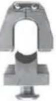 | Indentor:PoinçonStempelPunzónPunzone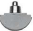 | Containing die - Matrice coquille - Presseinsatzschale -Matrice de sujección - Matrice di contenimento | |||
| Short - Courte -Kurz - Corla - Corla | Long - Longue - Lang - Larga - Lunga | Universal - Universelles- Universal -Universale - Universale | ||||||
 |  |  |  | |||||
| 10 - 16 | AU 130-150 | AC 130-P | PS 130-35/E | MV 35 | MVM 35 | MUA 35 | ||
| 25 | UP 130-25 | |||||||
| 35 | UP 130-35 | |||||||
| 50 | UP 130-50 | PS 130-95/E | MV 95 | MVM 95 | MVC 95 | MUA 95 | ||
| 70 | UP 130-70 | |||||||
| 95 | UP 130-95 | |||||||
| 120 | UP 130-120 | PS 130-150/E | MV 150 | MVM 150 | MVC 150 | MUA 150 | ||
| 150 | UP 130-150 | |||||||
| 185 | AU 130-240 | UP 130-185 | PS 130-240/E | MV 240 | MVM 240 | MVC 240 | MUA 240 | |
| 240 | UP 130-240 | |||||||
| 300 * | UP130-300 | MUA 300-34 | ||||||
| e diameter of connector = 34mmtre exterieur connecteur = 34mmder Aussendurchmesser = 34mmtro externo conector = 34mm | CAA.-MMTA.-C | MTMA... | MTA... | AA...M | ||||
| CONNECTORS - CONNECTEURS - VERBINDER - CONECTORES - CONNETTORI | ||||||||
Outside diameter of connector = 34mm Diametre exterieur connecteur = 34mm
Verbinder Aussendurchmesser = 34mm Diametro externo conector = 34mm
Kingsbury Road, Curdworth - Sutton Coldfield
West Midlands B76 9EB (UK)
Tel.: +44 01675 470440 - Fax: +44 01675 470220
E-mail:sales@cembre.co.uk
www.cembre.co.uk
Cembre S.a.r.l.
22 Avenue Ferdinand de Lesseps
91420 Morangis (France)
Tél.: +33 01 60 49 11 90 - Fax: +33 01 60 49 29 10
CS 92014 - 91423 Morangis Cédex
E-mail: info@cembre.fr
www.cembre.fr
Raritan Center Business Park
181 Fieldcrest Avenue
Edison, New Jersey 08837 (USA)
Tel.: +1 732 225-7415 - Fax: +1 732 225-7414
E-mail: sales.US@cembre.com
www.cembreinc.com