PNB1 - Hydraulic press Cembre - Free user manual and instructions
Find the device manual for free PNB1 Cembre in PDF.

User questions about PNB1 Cembre
0 question about this device. Answer the ones you know or ask your own.
Ask a new question about this device
Download the instructions for your Hydraulic press in PDF format for free! Find your manual PNB1 - Cembre and take your electronic device back in hand. On this page are published all the documents necessary for the use of your device. PNB1 by Cembre.
USER MANUAL PNB1 Cembre
natural_image
Abstract 3D geometric shape resembling a stylized letter or symbol (no text or symbols present)Cembre
07 M 012

Certified Quality Management System

Certified Environmental Management System

Certified Occupational Health & Safety Management System
ENGLISH
FRANÇAIS
DEUTSCH
ESPAÑOL
ITALIANO
PNEUMO-HYDRAULIC BENCH PRESS PRESSE HYDRO-PNEUMATIQUE D'ETABLI PNEUMATISCHE ÖLDRUCKTISCHPRESSE PRENSA NEUMO-HIDRAULICA DE BANCO PRESSA PNEUMO-OLEODINAMICA DA BANCO
PNB-1
CE

OPERATION AND MAINTENANCE MANUAL NOTICE D'UTILISATION ET ENTRETIEN BEDIENUNGSANLEITUNG MANUAL DE USO Y MANTENIMIENTO MANUALE D'USO E MANUTENZIONE
WARNING LABELS - ETIQUETTES SIGNALETIQUES - WARNSCHILDER - ETIQUETAS DE ATENCION - ETICHETTE D'AVVERTENZA

natural_image
Warning symbol depicting a mechanical or electrical hazard, with no text or numbers present.TG 0366
- Before using the press, carefully read the instructions in this manual.
- Avant d'utiliser la presse, lire attentivement les instructions de cette notice.
- Vor dem Bedienen der Presse lesen Sie bitte aufmerksam die Anweisungen in diesem Handbuch durch.
- Antes de utilizar la prensa, leer atentamente las instrucciones contenidas en este manual.
-
Prima di utilizzare la pressa, leggere attentamente le istruzioni contenute in questo manuale.
-
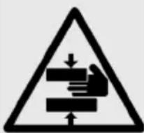
When operating the press, keep hands away from the danger zone.
- Au cours d'utilisation, tenir les mains éloignées de la zone de danger.
- Während der Benutzung nicht mit den Händen in den Gefahrenbereich gelangen.
- Durante su utilización, mantenga las manos fuera de la zona de peligro.
- Durante l'utilizzo, mantenere le mani fuori dalla zona di pericolo.

Via Serenissima, 9 - 25135 Brescia - Italy
TIPO TYPE
MATRICOLA SERIAL
PRESSIONE ARIA AIR PRESSURE
No.
bar
Made in Italy
PNB-1
6

①
2
3
4
| 1- Press type- Presse type- Pressentyp- Prensa tipo- Tipo di pressa | 2- Serial No.- No. de série- Serien Nr.- No. de serie- N° Matricola | 3- Air pressure- Pression air- Luftdruck- Presión aire- Pressione aria | 4- Year- Année- Jahr- Año- Anno |
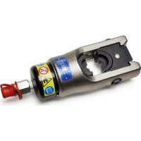
PNEUMO-HYDRAULIC BENCH PRESS TYPE PNB-1
Pneumo-hydraulic bench press with automatic work cycle controlled by pneumatic logic, suitable for installing all types of electric connectors up to 50 mm^2 .
1. GENERAL CHARACTERISTICS
- Inlet air pressure: 6 bar
- Compression force: 3600 daN
- Die stroke: 16 mm
- Dimensions: length....320 mm width....180 mm height....700 mm
- Weight: 24 kg
- Air connection: 1/4" Female
- Recommended oil:...... ENI ARNICA ISO 32 or SHELL TELLUS OIL TX 32 or equivalent
- Acoustic noise (Directive 2006/42/EC, annexe 1, point 1.7.4.2 letter u)
- The weighted continuous acoustic pressure level equivalent A at the work place L_nA is equal to 65.8 dB (A)
- The maximum value of the weighted acoustic displacement pressure C at the work place L _pCPeak is ....../< 130 dB (C)
- The acoustic power level emitted by the machine L_WA is equal to....72,2 dB (A)
- The work area is provided with a safety guard in compliance with the safety standards as regards size and which has slots in the side for the passage of the conductors with connector to be compressed. Changes to or tampering with the above protection releases the supplier from all civil and penal responsibility. Therefore, should parts of the guard get broken and before using the press again, the guard must be replaced completely so as to restore the safety conditions. The protection is the "fixed with start control" type (UNI EN 292/2 § 3.22.6 and 2006/42/EC) and is fixed to the frame of the press by a locking knob; removal of the guard impedes the press from being used in that both the pneumatic logic and the main feed valve are disabled; all the air present in the pneumatic circuit downstream of the main valve is automatically released.
- The press is in compliance with the Directive:
2006/42/EC; it is marked C€, and is supplied with an instruction and maintenance manual and a certificate of compliance.
- The press is supplied complete with:
- transportation cap (13) for the oil tank (to be used only for transport).
- oil filler cap with dipstick (14).
- manual control (26).
-
Qty 4 safety guards (17-18-19-20).
-
5 mm "T" allen key.
- 3 mm allen key.
- die holder case type "VAL 75".
2. FIELD OF APPLICATION
The press is suitable for crimping the range of connectors listed on pages 31, 32, 33 and 34. The tables also list the conductor reference, die reference and the appropriate safety guard.
3. INSTRUCTIONS FOR USE
3.1) Setting (Ref. to Figs. 4 - 5)
3.1.1) Replace the transportation cap (13) with the oil filler cap (14) (see Fig. 4).
3.1.2) Position the press on a work bench: remove the safety guard if assembled.
3.1.3) Connect the manual control using the quick couplers (24) and (25) located on the left hand side of the machine.
3.1.4) Connect the press to the compressed air supply using the pneumatic air coupling located on the rear of the machine.
3.1.5) Turn the main air valve to the "SUP" position; check the front manometer and if necessary, adjust the pressure through the reducer (15) till the value of 6 bar is reached.
3.1.6) Select the appropriate die set for the connector and the associated safety guard from the tables on pages 31, 32, 33, and 34.
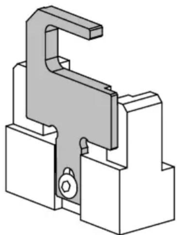
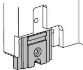
3.1.7) If necessary, adjust the extractor (09), using the 3 mm allen key.
For ANE 7-M.... and ANE 9 M.... type connectors, the extractor must be fully raised (see Fig. 1).
3.1.8) If you use front access dies to compress insulated or uninsulated end sleeves, remove the extractor first.
3.2) Die installation (Ref. to Figs. 6 and 7)
When assembling the dies, use the following sequence:
natural_image
Technical line drawing of a mechanical clamp or bracket component (no text or symbols)FIG. 1 EXTRACTOR POSITION
3.2.1) Upper die
- Using the 5 mm allen key, loosen the clamp screw (10).
- Insert the die in the housing in the sliding carriage, making sure the impression is facing downwards; the coloured reference mark on the die should correspond with the mark on the die support (11).
- Tighten the clamp screw (10).
3.2.2) Lower die
- Using a 5 mm allen key, loosen the clamp screw (06).
- Insert the die into the housing in the lower die support (07) making sure that the impression is facing upwards; the coloured reference mark on the die should correspond with the mark on the lower die support (07).
- Leave the clamp screw loose and fit the appropriate safety guard (see § 3.3).
- Press and hold the manual control (26). The machine will cycle, the upper die will touch the lower die and ensure correct alignment of the dies.
Continue to hold the pedal and tighten the clamp screw (06) to lock the lower die in position. - Release the pedal.
N.B.: for "high and low" positioning of dies without reference marks (type MTT...-50, MN... RF-50) see the relative figures given in the tables on pages 32 and 34.
Symmetrical dies may be positioned as required.
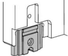
3.3) Fitting the safety guard
- Position the guard on the press and insert the pin (21) attached to the rear of the guard, into the main body (12).
- Tighten the knob (23) into the die support (07). The guard will move forward, activate the safety devices and switch on the air feed.
- The press is now ready for operation.
3.4) Die removal
When changing dies proceed as follows:
- Turn the main air valve (16) to the "EXH" position.
This cuts off the air supply and discharges any air pressure within the machine. - Remove the safety guard.
- Unscrew clamp screw (10) and remove the upper die.
- Unscrew clamp screw (06) and remove the lower die.
– Insert the replacement dies (see 3.2).
3.5) Oil top up
Every six months check the oil level, using the dipstick on the oil filler cap (14).
The level should be between the two reference marks. If necessary, top up with the recommended oil (see 1) to the "MAX" mark.
Ensure that disposal of used oil is in accordance with current legislation.
4. RETURN TO Cembre FOR OVERHAUL
In the case of a breakdown contact our Area Agent who will advise you on the problem and give you the necessary instructions on how to dispatch the tool to our nearest service Centre; if possible, attach a copy of the Test Certificate supplied by Cembre together with the tool or fill in and attach the form available in the "ASSISTANCE" section of the Cembre website.
ENGLISH
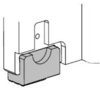
5. DIES (Ref. to Fig. 2)
The dies available for this press have either front cable entry or side cable entry.
- dies with front cable entry (Fig. 2a) type: KE 2.5-1; KE 10-1.
- dies with side cable entry (Fig. 2b) type: ME...-50 ; PR-1 ; PB-1 ; PG-1 ; MN...RF- 50 ; MTT...-50.
a)
natural_image
Technical line drawing of a mechanical bracket or bracket assembly (no text or symbols)b)
natural_image
Technical line drawing of a mechanical bracket or mounting bracket (no text or symbols)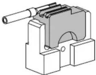
natural_image
Technical illustration of a mechanical clamp or bracket component (no text or symbols)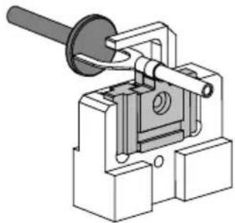
natural_image
Mechanical component diagram showing a lever and housing assembly (no text or symbols)FIG. 2 DIES:
a) front cable entry b) side cable entry
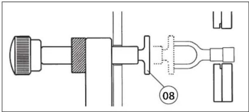
FIG. 3 POSITIONER ADJUSTMENT
6. OPERATION
For a complete operation cycle (i.e. compression and release) press and release the manual control (26); it is not necessary to hold down the pedal. The pedal must to be released in order to execute another cycle.
The duration of the cycle is factory set at two seconds.
6.1) Connectors requiring side cable entry
Set the location of the positioner (08) to suit each size and type of connector (see Fig. 3):
- Insert the conductor into the connector and locate between the dies at the desired crimp position. Adjust the stop on the positioner (08) to suit the particular size and type of connector (see Fig. 9). The connector should just touch the stop.
At this position, tighten the knurled nut to secure the positioner.
- Insert the conductor into the connector.
- Insert the connector/conductor assembly through the opening in the side of the safety guard and without exerting any pressure position the connector up against the positioner.
- Depress the manual control (26) to operate the press.
- Remove the crimped assembly.
6.2) Connectors requiring front access dies
- Insert the conductor into the connector
- Insert the connector/conductor assembly through the opening in the front of the safety guard into the appropriate aperture of the bottom die until the collar of the barrel is in contact with the die itself.
- Depress the manual control (26) to operate the press.
-
Remove the crimped assembly.
-
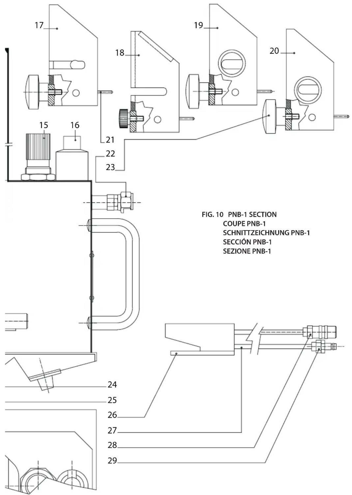
PARTS LIST (Ref. to Fig. 10)
| Code N° | Item | DESCRIPTION | Qty |
| 6232166 | 01 LABEL (TG. 0366) 1 | ||
| 6895086 | 02 AIR ON-OFF VALVE 1 | ||
| 6072016 | 03 LONG CONTROL ROD 1 | ||
| 6895085 | 04 CONTROL FEED VALVE | 1 | |
| 6072015 | 05 SHORT CONTROL ROD | 1 | |
| 6790024 | 06 LOWER DIE CLAMP | 1 | |
| 6780365 | 07 LOWER DIE SUPPORT | 1 | |
| 6504126 | 08 POSITIONER | 1 | |
| 6240170 | 09 WIRE TERMINAL EXTRACTOR | 1 | |
| 6790024 | 10 UPPER DIE CLAMP | 1 | |
| 6090576 | 11 UPPER DIE SUPPORT | 1 | |
| 6780363 | 12 MAIN SUPPORT | 1 | |
| 6800063 | 13 TRANSPORTATION CAP | 1 | |
| 6800062 | 14 OIL FILLER CAP WITH DIPSTICK | 1 | |
| 6250047 | 15 REDUCTION UNIT FILTER | 1 | |
| 6895087 | 16 MAIN AIR VALVE | 1 | |
| 6631024 | 17 PU-1 GUARD | 1 | |
| 6631029 | 18 PK-1 GUARD | 1 | |
| 6631022 | 19 ME-1 GUARD | 1 | |
| 6631023 | 20 M NRF-1 GUARD | 1 | |
| 6760166 | 21 CYLINDRICAL PIN | 4 | |
| 6650052 | 22 COUPLER | 3 | |
| 6480659 | 23 KNOB | 1 | |
| 6650058 | 24 MALE COUPLER | 1 | |
| 6650066 | 25 MALE CONNECTOR | 1 | |
| 6550053 | 26 COMPLETE MANUAL CONTROL | 1 | |
| 6890032 | 27 PU 4 HOSE | 3 m | |
| 6650064 | 28 MALE COUPLER | 1 | |
| 6650062 | 29 MALE CONNECTOR | 1 |
The guarantee is void if parts used are not Cembre original spares.
When ordering spare parts always specify the following:
- code number of item
- name of item
- type of tool
- tool serial number
PRESSE HYDRO-PNEUMATIQUE D'ETABLI
TYPE PNB-1
natural_image
Technical line drawing of a mechanical clamp or bracket component (no text or symbols)FIG. 1 POSITION DE L'EXTRACTEUR
natural_image
Four technical diagrams showing mechanical assembly steps (a, b) with no visible text or symbolsnatural_image
Technical line drawing of a mechanical clamp or bracket component (no text or symbols)natural_image
Technical line drawing of a mechanical bracket with mounting holes and a curved cutout (no text or symbols)b)
natural_image
Technical line drawing of a mechanical bracket or mounting bracket (no text or symbols)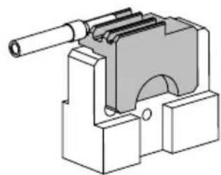
natural_image
Technical illustration of a mechanical clamp or bracket component (no text or symbols)
natural_image
Mechanical assembly diagram showing a lever mechanism with no visible text or symbolsnatural_image
Technical line drawing of a mechanical clamp or bracket component (no text or symbols)5. MATRICES (Ref. a Fig. 2)
natural_image
Four technical diagrams showing mechanical assembly steps (a, b) with no visible text or symbolsnatural_image
Technical line drawing of a mechanical clamp or bracket component (no text or symbols)natural_image
Four technical diagrams showing mechanical assembly steps (a, b) with no visible text or symbolsnatural_image
Close-up of a mechanical assembly with labeled parts (06, 07), no readable text or symbols beyond labels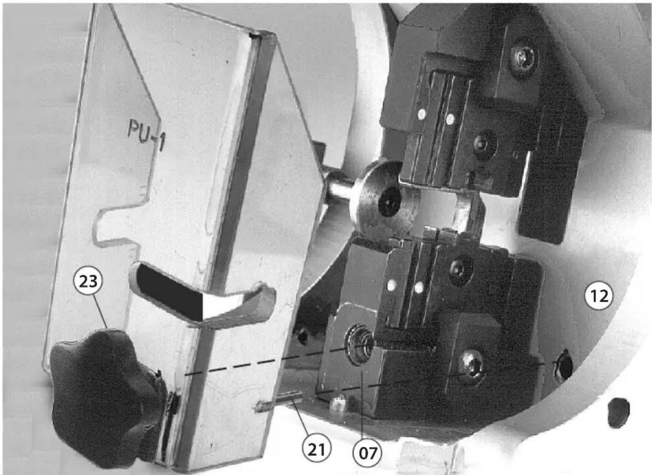
FIG. 8 ASSEMBLING THE SAFETY GUARD
MONTAGE DE LA PROTECTION
natural_image
Close-up of a mechanical device with a metallic tool and metal bracket (no visible text or symbols)
| CONNECTOR TYPE CONNECTEUR TYPE KABELSCHUHTYP CONECTOR TIPO CONNETTORE TIPO | CABLE CROSS SECTION SECTION CABLE KABELQUERSCHNITT SECCIÓN CABLE SEZIONE CAVO (mm2) | DIE MATRICE MATRIZE MATRIZ MATRICE | REF. MARK COLOUR ETIQUETTE REPERE COULEUR FARBKENNZEICHNUNG ETIQUETA REFERENCIA COLOR BOLLO RIFERIMENTO COLORE | GUARD PROTECTION ABDECKUNG PROTECCIÓN PROTEZIONE | POSITIONER POSITION POSITIONIERHILFE POSICIÓN POSIZIONATORE | ||
| VP-M...VP-U....VP-P.../-PP.... | 0,2÷0,5(AWG 24÷20) | PV-1 | ◆ | PU-1 YES | |||
| RF-M...RF-U....RF-P.../-PP.... | 0,25÷1,5(AWG 22÷16) | PR-1 | ● | PU-1 | YES | ||
| BF-M...BF-U...BF-P.../-PP.... | 1,5÷2,5(AWG 16÷14) | PB-1 | ▼ | ||||
| GF-M...GF-U...GF-P.../-PP.... | 4÷6(AWG 12÷10) | PG-1 | ■ | ||||
| RF-F...RF-M... | 0,25÷1,5(AWG 22÷16) | PR-1 | ● | ||||
| BF-F...BF-M... | 1,5÷2,5(AWG 16÷14) | PB-1 | ▼ | ||||
| GF-F... | 4÷6(AWG 12÷10) | PG-1 | ■ | ||||
| RF-F...PRF-M...P | 0,25÷1,5(AWG 22÷16) | PR-1 | ● | ||||
| BF-F...PBF-M...P | 1,5÷2,5(AWG 16÷14) | PB-1 | ▼ | ||||
| GF-F...P PG-1 | 4÷6(AWG 12÷10) | ■ | |||||
| RF-BM4RF-BF4 | 0,5÷1,5(AWG 18÷16) | PR-1 | ● | ||||
| BF-BM5BF-BF5 | 1,5÷2,5(AWG 16÷14) | PB-1 | ▼ | ||||
| PL03-M PR-1 | 0,25÷1,5(AWG 22÷16) | ● | PK-1 NO | ||||
| PL06-M | 1,5÷2,5(AWG 16÷14) | PB-1 | ▼ | ||||
| PL1-M | 4÷6(AWG 12÷10) | PG-1 | ■ | ||||
● Blue - Bleu - Blau - Azul - Blu
◆ Green - Vert - Grün - Verde - Verde
● Red - Rouge - Rot - Rojo - Rosso
■ Yellow - Jaune - Gelb - Amarillo - Giallo
| CONNECTOR TYPE CONNECTEUR TYPE KABELSCHUHTYP CONECTOR TIPO CONNETTORE TIPO | CABLE CROSS SECTION SECTION CABLE KABELQUERSCHNITT SECCION CABLE SEZIONE CAVO (mm2) | (★) DIE MATRICE MATRIZE MATRIZ MATRICE | GUARD PROTECTION ABDECKUNG PROTECCIÓN PROTEZIONE | POSITIONER POSITION POSITIONIERHILFE POSICIÓN POSIZIONATORE | |
| A 03 - M... | 0,25 - 1,5 | N1-1 | PU-1 | YES | |
| S1,5 - M..../-U..../-P.../-PP | |||||
| RN - M..../-U..../-P.../-PP | |||||
| A 06 - M... | 1,5 - 2,5 | ||||
| S 2,5 - M..../-U..../-P.../-PP | |||||
| BN - M..../-U..../-P.../-PP | |||||
| A 1 - M... | 4 - 6 | ||||
| S 6 - M..../-U..../-P.../-PP | |||||
| GN - M..../-U..../-P.../-PP | |||||
| A 1 - M... | 4-6 | ME 1-50 | PU-1 | ||
| A 2 - M.../-P... ; S10-M... | 10 | ME 2-50 | ME-1 | ||
| A 3 - M.../-P... | 16 | ME 3-50 | |||
| A 5 - M.../-P... | 25 | ME 5-50 | |||
| A 7 - M.../-P... | 25-35 | ME 7-50 | |||
| A 10 - M.../-P... | 50 | ME10-50 | |||
| A 12 - M... | 50 | ME12-50 | |||
| T 6 - M... | 4-6 | MS 6-50 | PU-1 | ||
| T 10 - M... | 10 | MS10-50 | ME-1 | ||
| T 16 - M... | 16 | MS16-50 | |||
| T 25 - M... | 25 | MS25-50 | |||
| T 35 - M... | 25-35 | MS35-50 | |||
| T 50 - M... | 50 | MS50-50 | |||
| HR 10 - .... | 10 | MH10-50 | ME-1 | ||
| HR 16 - .... | 16 | MH16-50 | |||
| HR 25 - .... | 25 | MH25-50 | |||
| HR 35 - .... | 35 | MH35-50 | |||
| HR 50 - .... | 50 | MH50-50 | |||
| ANE 2 - M.../-P.../-U... | 10 | MN2 RF-50 | MNRF-1 | ||
| ANE 3 - M.../-P.../-U... | 16 | MN3 RF-50 | |||
| ANE 5 - M.../-P.../-U... | 25 | MN5 RF-50 | |||
| ANE 7 - M.../-P.../-U... * | 25 - 35 | MN7 RF-50 | |||
| ANE 9 - M.../-P.../-U... * |
(✗) Die sets for crimping DIN 46 234 lugs section 6 to 25 sqmm are available:
* Adjustment of extractor position required (see § 3 page 3)
In order to assemble these dies, it is necessary to remove the extractor (09).
Kingsbury Road, Curdworth - Sutton Coldfield
West Midlands B76 9EB (UK)
Tel.: 01675 470440 - Fax: 01675 470220
E-mail: sales@cembre.co.uk
www.cembre.co.uk
Cembre S.a.r.l.
22 Avenue Ferdinand de Lesseps
91420 Morangis (France)
Tél.: 01 60 49 11 90 - Fax: 01 60 49 29 10
CS 92014 - 91423 Morangis Cédex
E-mail: info@cembre.fr
www.cembre.fr
Raritan Center Business Park
181 Fieldcrest Avenue
Edison, New Jersey 08837 (USA)
Tel.: (732) 225-7415 - Fax: (732) 225-7414
E-mail: sales.US@cembreinc.com
www.cembreinc.com