HTTC0851 - Hydraulic cutting tool Cembre - Free user manual and instructions
Find the device manual for free HTTC0851 Cembre in PDF.

| Product type | Hydraulic cutting tool |
| Brand | Cembre |
| Model | HTTC0851 |
| Height | 652.5 mm (25.7 in) |
| Width | 175 mm (5.6 in) |
| Weight | 6.6 kg (14.5 lb) |
| Rated pressure | 700 bar (10,000 psi) |
| Recommended oil type | ENI ARNICA 32, SHELL TELLUS OIL TX 32 or equivalent |
| Max cutting capacity (Cu/Al cable) | Outer diameter 85 mm (3 3/8 in) |
| Compatible cable types | Copper, aluminum, telephone cables |
| Rapid advance | Automatic shift from fast to slow speed |
| Safety | Integrated pressure relief valve |
| Head rotation | 180° relative to the body |
| Operating positions | Rest, decompression, work |
| Blade replacement | Possible, lower and upper blades |
| Storage case | Model VAL-P7 (727x202x115 mm, 1.3 kg) |
| Maintenance | Daily cleaning, bleeding air bubbles if necessary |
| Spare parts | Available, recommended spare parts kit (★) |
| Manual pages | 32 pages |
Frequently Asked Questions - HTTC0851 Cembre
User questions about HTTC0851 Cembre
0 question about this device. Answer the ones you know or ask your own.
Ask a new question about this device
Download the instructions for your Hydraulic cutting tool in PDF format for free! Find your manual HTTC0851 - Cembre and take your electronic device back in hand. On this page are published all the documents necessary for the use of your device. HTTC0851 by Cembre.
USER MANUAL HTTC0851 Cembre
natural_image
Abstract 3D geometric shape resembling a stylized letter or symbol (no text or symbols present)Cembre

Certified Quality Management System

Certified Environmental Management System

Certified Occupational Health&Safety Management System
ENGLISH
FRANÇAIS
DEUTSCH
ESPAÑOL
ITALIANO
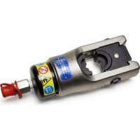
HYDRAULIC CUTTING TOOL COUPE-CABLE HYDRAULIQUE HYDRAULISCHES SCHNEIDWERKZEUG HERRAMIENTA HIDRAULICA DE CORTE UTENSILE OLEODINAMICO DA TAGLIO
HT-TC0851

natural_image
Black mechanical crimping tool with multiple arms and a handle (no visible text or symbols)OPERATION AND MAINTENANCE MANUAL NOTICE D'UTILISATION ET ENTRETIEN BEDIENUNGSANLEITUNG MANUAL DE USO Y MANTENIMIENTO MANUALE D'USO E MANUTENZIONE
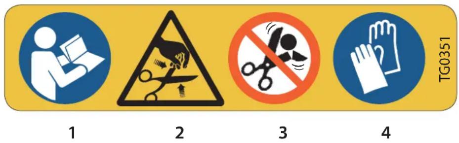
| 1 | – Before using the tool, carefully read instructions in this manual.– Avant d'utiliser cet outil, lire attentivement les instructions de cette notice.– Vor Inbetriebnahme unbedingt die Bedienungsanleitung durchlesen.– Antes de utilizar la herramienta, leer atentamente las instrucciones contenidas en este manual.– Prima di utilizzare l'utensile, leggere attentamente le istruzioni contenute in questo manuale. |
| 2 | – Keep hands clear of cutting blades.– Au cours du coupage, tenir les mains loin des lames.– Während des Schneidens, die Hände von den Messern fernhalten.– Durante la cortadura, tener las manos alejadas de las cuchillas.– Durante il taglio, tenere le mani lontane dalle lame. |
| 3 | – Do not cut steel.– Ne pas couper l'acier et l'almélec.– Keinen Stahl schneiden.– No cortar acero.– Non tagliare acciaio. |
| 4 | – Always wear safety glasses and gloves when operating this tool.– Porter toujours les lunettes de protection et les gants de travail.– Immer mit Schutzbrille und Handschuhen bedienen.– Trabajar siempre de con las gafas y guantes de seguridad.– Operare sempre con visiera protettiva e guanti da lavoro. |


- Tool type
- Outil type
- Handwerkzeug Typ
- Herramienta tipo
- Tipo di utensile

- max cutting diam.
- ∅ maxi de coupe
- max. Schneid. ∅
- ∅ max de corte
- ∅ max di taglio

- Application range: is suitable for cutting copper, aluminium or telephone cables having a max. diameter of.... 85 mm (3 - 3/8 in.)
- Rated operating pressure: 700 bar (10,000 psi)
- Dimensions: length....652,5 mm (25.7 in.) width....175 mm (5.6 in.)
- Weight: 6,6 kg (14.5 lbs)
- Oil: ENI ARNICA ISO 32 or SHELL TELLUS OIL TX 32 or equivalent
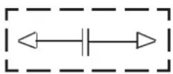
- Operating positions. The three operating positions are identified on the main handle, (04), which rotates relative to the reference symbol (see Fig. 1).

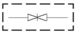
Rest position (Handles locked): lock handles together when tool is not in use.
Release position: close the moveable handle (59) against the main handle (04), in order to discharge the oil pressure and retract the lower blade.
Operating position: operate the moveable handle (59), to build up pressure and close the lower blade.
- Advancing speed. The tool automatically switches from a fast advancing speed of blades to a slower cutting speed.
- Safety. The tool is provided with max pressure valve; MPC1 special manometer, is available upon request to check the proper setting of the valve.
2. RETURN TO Cembre FOR OVERHAUL
In the case of a breakdown contact our Area Agent who will advise you on the problem and give you the necessary instructions on how to dispatch the tool to our nearest service Centre; if possible, attach a copy of the Test Certificate supplied by Cembre together with the tool or fill in and attach the form available in the "ASSISTANCE" section of the Cembre website.
3. INSTRUCTIONS FOR USE (Ref. to Fig. 1 and 2)
3.1) Setting
With the tool is in rest position □ operate as follows:
- Insert the conductor between the blades at the desired cutting point.
For a running conductor, press latch (33) and open the upper blade assembly.
Warning: the opening of upper blade must be done when the tool is in rest position, lower blade completely retracted.
- With the conductor on the lower blade (25), close the upper blade assembly and secure the latch (33).
Check carefully that latch is firmly engaged before starting to cut.
3.2) Blade advancement
- Rotate clockwise main handle (04), to release position thus releasing the moveable handle (59). Hold tool by both handles during the cutting operation.
- Rotate main handle to operating position
- Operate moveable handle (59) for lower blade advancement. This first stage rapidly closes the lower blade (25) to the conductor. Make sure that blades are exactly positioned on desired cutting point, otherwise re-open blades following instructions as per § 3.4 and position the conductor again.
3.3) Cutting
- Continue operating the moveable handle, the lower blade advances gradually until the conductor is fully cut.
The tool is designed for cutting copper, aluminium and telephone cables: do not attempt to cut steel or ACSR conductors.
3.4) Blade retraction
- Rotate main handle clockwise to release position
Completely close handles and the lower blade will retract.
3.5) Rest setting
- Completely retract the ram as § 3.4.
- Close handles and rotate main handle to rest position ▷ ▷ ▷; the moveable handle will be locked.
- Store the tool in the plastic case.
3.6) Blade replacement (Ref. to Fig. 2)
After extended use, the blades may lose their cutting edge.
Replace the blades as follows:
3.6.1) Lower blade:
- Press latch (33) and open upper blade assembly (27).
- Pump the moveable handle (59) to make the lower blade (25) advance until fixing pin (87) is visible on ram.
- Remove fixing pin (87) and remove the lower blade (25).
- Insert new blade and secure with fixing pin (87).
Warning: before closing the upper blade assembly, release the oil pressure and retract the lower blade, otherwise the blade may hit the upper blade edge and damage it.
3.6.2) Upper blade:
- Press latch (33) and open upper blade assembly (27).
- Remove circlip (93) and pivot (92).
- By an hexagonal 13 mm, undo M8 nuts (94) and remove two studs (97), blade guide (95) blade spacer (96) and upper blade (27), noting the order of assembly.
- Fitting the new blade is a reversal of the above.
4. WARNING
The tool is robust and requires very little daily maintenance.
Compliance with the following points, should help to maintain the optimum performance of the tool:
4.1) Accurate cleaning
Dust, sand and dirt are a danger for any hydraulic device.
Every day, after use, the tool must be cleaned with a clean cloth, taking care to remove any residual, especially close to pivots and moveable parts.
4.2) Storage (Ref. to Fig. 3)
When not in use, the tool should be stored and transported in the plastic case, to prevent damage. These plastic case VAL-P7, is dimensioned 727x202x115 mm (28.6x8x4.5 in.) and weights 1,3 kg (2.9 lbs).
4.3) Head rotation
For ease of operation, the tool head can rotate through 180^ .
Warning: Do not attempt to turn the head if the hydraulic circuit is pressurised.
5. MAINTENANCE (Ref. to Fig. 4 and 5)
Air in the hydraulic circuit may affect the performance of the tool; e.g: no lower blade advancement, slow advancement of the lower die; lower blade pulsating.
In this case proceed as follows:
5.1) To purge air bubbles from hydraulic circuit
a - Hold tool upright position in a vice with handles open (Fig. 4).
b – By an hexagonal 2,5 mm key, remove screw (67) and main handle (04) to expose oil reservoir (03).
c - Remove reservoir cap (01).
d - Operate three or four times the moveable handle (59), to advanced the ram (39).
e – Depress pressure release pin (75) until ram is fully retracted.
f - Repeat points (d - e) at least five times, to ensure all air bubbles in the hydraulic circuit are into the reservoir.
g – Remove all air from reservoir.
If the oil level is low, top up as directed in § 5.2.
h - Fit reservoir cap (01).
i - Assemble main handle (04) and holding screw (67).
If the tool continues to malfunction return the tool for service/repair as detailed in § 2.
5.2) Oil top up
Every six months check the oil level in the reservoir. If necessary, top up the oil level to the top lip of the reservoir and remove all air from reservoir, see § 5.1, points a, b, c and e, finally, complete with operations h and i.
Always use clean recommended oil, see § 1.
Do not use old or recycled oil.
Do not use hydraulic brake fluid.

Upon its replacement, dispose of used oil strictly conforming with what prescribed by the relevant norms specifically applying.
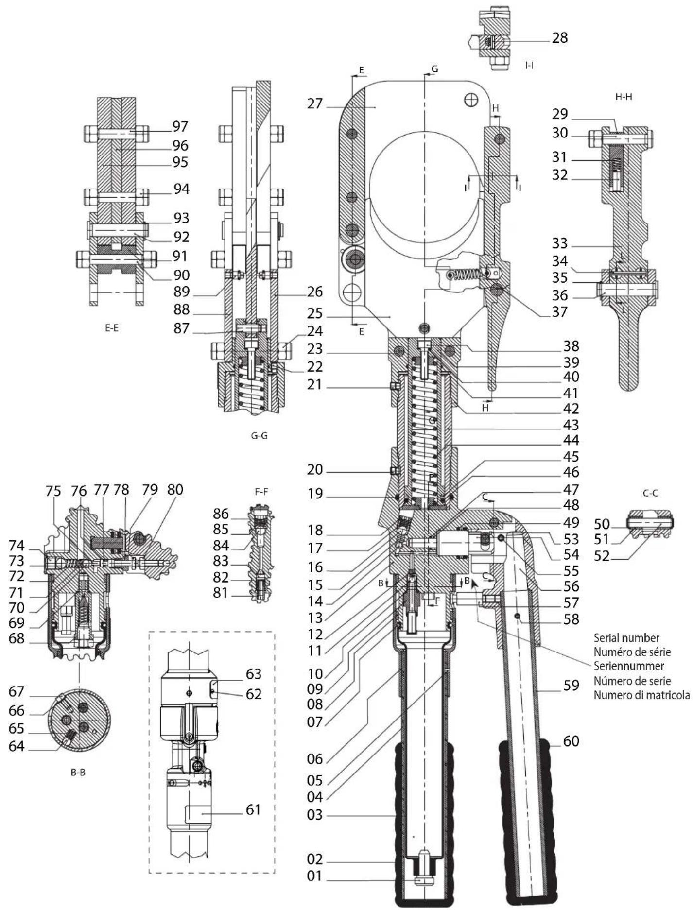
- PARTS LIST (Ref. to Fig. 5)
| Code N° | Item DESCRIPTION Qty | ||
| 6800040 01 | RESERVO | R CAP 1 | |
| 6380265 | ● 02 | MAIN HANDLE GRIP 1 | |
| 6720100 03 | OIL RESERVOIR 1 | ||
| 6480043 | ● 04 | MAIN HANDLE 1 | |
| 6760014 | ● 05 | PIN D. 3x4 1 | |
| 6780105 | ● 06 | MAIN HANDLE SUPPORT 1 | |
| 6360260 | ★ 07 | O-RING 1 | |
| 6040685 08 | GUIDING | RING 2 | |
| 6900621 09 | COMPLETE SUCTION SCREW | 1 | |
| 6360161 | ★ 10 | O-RING | 1 |
| 6740060 | ★ 11 | 3/16" BALL | 1 |
| 6520765 | ★ 12 | SUCTION SPRING | 1 |
| 6160055 13 | BODY | 1 | |
| 6740060 | ★ 14 | 3/16" BALL | 1 |
| 6520765 | ★ 15 | SUCTION SPRING | 1 |
| 6740140 | ★ 16 | 9/32" BALL | 1 |
| 6520180 | ★ 17 | SPRING | 1 |
| 6340566 18 | BALL POSITIONING DOWEL | 1 | |
| 6360112 | ★ 19 | O-RING 1 | |
| 6340060 20 | M 6x6 GRUB SCREW 1 | ||
| 6340041 | ■ 22 | M 5x8 GRUB SCREW 1 | |
| 6580161 23 | LOWER FIXING STUD | 2 | |
| 6180345 24 | M 8 SELF-LOCK NUT 4 | ||
| 6420232 25 | LOWER BLADE | 1 | |
| 6580110 | ▲ 26 | FIXING PLATE | 1 |
| 6420242 | ▲ 27 | UPPER BLADE | 1 |
| 6760080 | ▲ 28 | SPRING PIN D. 3x10 1 | |
| 6080114 | ▲ 29 | BOLT BUSHING 1 | |
| 6560720 | ▲ 30 | LATCH PIN 1 | |
| 6520280 | ▲ 31 | SPRING | 1 |
| 6560705 | ▲ 32 | BLADE PIN | 1 |
| 6440190 | ▲ 33 | LATCH | 1 |
| 6760160 | ▲ 34 | SPRING PIN D 3x28 | 1 |
| 6040421 | ▲ 35 | SPRING RING D. 10 | 1 |
| 6560695 | ▲ 36 | LEVER PIVOT | 1 |
| 6520405 | ▲ 37 | LATCH RETURN SPRING 2 | |
| 6900453 | ■ × 38 | M 6x40 SCREW 1 | |
| 6620172 | ■ 39 | PISTON | 1 |
| 6641020 | ■ × ★ 40 | COPPER WASHER | 1 |
| 6360171 | ■ ★ 41 | O-RING 1 | |
| 6780190 | ■ 42 | PLATE SUPPORT | 1 |
| 6080120 | ■ 43 | RAM BUSH | 1 |
| - | ■ × 44 | SPRING | 1 |
| 6040220 | ■ ★ 45 | BACK-UP RING 1 | |
| 6360300 | ■ ★ 46 | O-RING 1 | |
| 6362010 | ★ 47 | SEAL | 1 |
| 6641140 | ★ 48 | BACK-UP RING 1 | |
| 6360240 | ★ 49 | O-RING 1 | |
| 6700100 | ★ 50 | CIRCLIP D. 7 | 4 |
| 6080060 | + 51 | MOVEABLE HANDLE BUSHING | 4 |
| 6560420 52 | MOVEABLE HANDLE PIN | 2 | |
| Code N° Item DESCR | IPTION Qty | ||
| 6362020 | ★ 53 | SEAL | 1 |
| 6620382 54 | PUMPING | RAM 1 | |
| 6760320 | + 55 | SPRING PIN D. 5x30 | 1 |
| 6780265 | + 56 | MOVEABLE HANDLE SUPPORT | 1 |
| 6200030 | + 57 | MOVEABLE HANDLE LATCH | 1 |
| 6760280 | + 58 | SPRING PIN D. 4x30 | 1 |
| 6480269 | + 59 | MOVEABLE HANDLE | 1 |
| 6380240 | + 60 | MOVEABLE HANDLE GRIP | 1 |
| 6232000 61 | LABEL TG | 0351 1 | |
| 6650118 62 | RIVET D. 2 | ,5x3,5 2 | |
| 6232158 63 | METAL LA | BEL TG 0358 1 | |
| 6740020 | ★ 64 | 1/4" BALL | 1 |
| 6520280 65 | SPRING | 1 | |
| 6640205 66 | M 4 WASH | HER 1 | |
| 6900080 67 | M 4x8 SCREW | 1 | |
| 6895050 68 | COMPLETE VALVE | 1 | |
| 6360161 | ★ 69 | O-RING 1 | |
| 6740120 | ★ 70 | 7/32" BALL | 1 |
| 6600100 71 | BALL POS | ITIONING DOWEL 1 | |
| 6520260 | ★ 72 | SPRING | 1 |
| 6740080 | ★ 73 | 5/16" BALL | 1 |
| 6340540 74 | M 10x8 GRUB SCREW | 1 | |
| 6620120 75 | PRESSURE RELEASE PIN | 1 | |
| 6360120 | ★ 76 | O-RING 1 | |
| 6040060 | ★ 77 | BACK-UP RING | 1 |
| 6080080 78 | PRES. RELE | ASE RAM BUSHING 1 | |
| 6900280 | + 79 | M 5x18 SCREW 1 | |
| 6180200 | + 80 | M 5 NUT | 1 |
| 6340720 81 | PRESSURE RELEASE DOWEL | 1 | |
| 6520861 82 | PRESSURE RELEASE SPRING | 1 | |
| 6635011 83 | PRESSURE RELEASE PIN | 1 | |
| 6740140 | ★ 84 | 9/32" BALL | 1 |
| 6520180 | ★ 85 | NO RETURN SPRING 1 | |
| 6340566 86 | BALL POS | ITIONING DOWEL 1 | |
| 6370250 87 | LOWER BL | ADE FIXING DOWEL 1 | |
| 6580111 | ▲ 88 | FIXING PLATE | 1 |
| 6560709 | ▲ 89 | SPRING PIN | 2 |
| 6580161 | ▲ 90 | LOWER FIXING STUD | 1 |
| 6080110 | ▲ 91 | BOLT BUSHING | 1 |
| 6560695 | ▲ 92 | LEVER PIVOT | 1 |
| 6040421 | ▲ 93 | CIRCLIP D. 10 | 1 |
| 6180345 | ▲ 94 | M 8 SELF-LOCK NUT 7 | |
| 6370160 | ▲ 95 | LOWER BLADE GUIDE | 1 |
| 6220190 | ▲ 96 | LOWER BLADE SPACER | 1 |
| 6580151 | ▲ 97 | UPPER FIXING STUD | 2 |
| 6480042 | ● | COMPLETE MAIN HANDLE | |
| 6480194 | + | COMPLETE MOVEABLE HANDLE | |
| 6860140 | ▲ | COMPLETE HEAD | |
| 6620560 | ■ | COMPLETE PISTON | |
| 6522318 | × | COMPLETE SPRING | |
| 6000047 | ★ | SPARE PARTS PACKAGE | |
The items marked ( ) are those Cembre recommends replacing if the tool is disassembled. These items are supplied on request in the "HT-TC0851 Spare Parts Package".
When ordering spare parts always specify the following:
- code number of item - name of item - type of tool - tool serial number
COUPE-CABLE HYDRAULIQUE TYPE HT-TC0851
1. CARACTERISTIQUES GENERALES
natural_image
Open cylindrical mechanical tool with handle and clasp, no visible text or symbols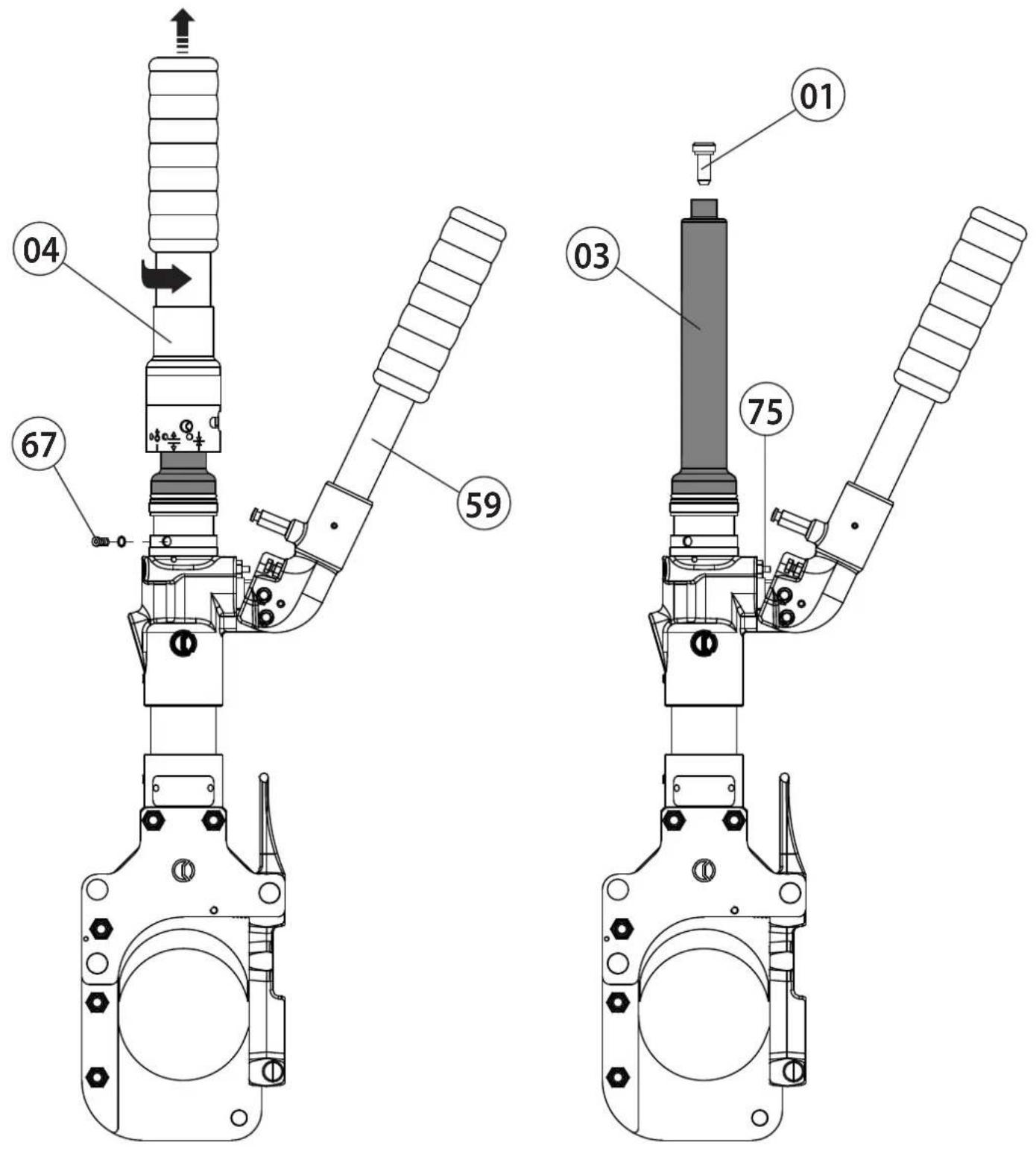
FIG. 4 TOOL POSITION FOR MAINTENANCE OPERATIONS
POSITION DE L'OUTIL POUR L'ENTRETIEN
WERKZEUG WARTUNGSPOSITION
COLOCACION PARA LAS OPERACIONES DE MANTENIMIENTO
POSIZIONAMENTO PER LE OPERAZIONI DI MANUTENZIONE
This manual is the property of Cembre: any reproduction is forbidden without written permission.
Kingsbury Road, Curdworth - Sutton Coldfield
West Midlands B76 9EB (UK)
Tel.: 01675 470440 - Fax: 01675 470220
E-mail: sales@cembre.co.uk
www.cembre.co.uk
Cembre S.a.r.l.
22 Avenue Ferdinand de Lesseps
91420 Morangis (France)
Tél.: 01 60 49 11 90 - Fax: 01 60 49 29 10
CS 92014 - 91423 Morangis Cédex
E-mail: info@cembre.fr
www.cembre.fr
Raritan Center Business Park
181 Fieldcrest Avenue
Edison, New Jersey 08837 (USA)
Tel.: (732) 225-7415 - Fax: (732) 225-7414
E-mail: sales.US@cembreinc.com
www.cembreinc.com