Phoenix Inverter Compact - Power inverter VICTRON ENERGY - Free user manual and instructions
Find the device manual for free Phoenix Inverter Compact VICTRON ENERGY in PDF.

| Product type | Power inverter (converter) |
| Brand and model | Victron Energy Phoenix Inverter Compact |
| Dimensions (H x W x D) | 520 x 255 x 125 mm |
| Weight | 12 kg |
| Input voltage | 9.5 – 17 V (12V) or 19 – 33 V (24V) depending on model |
| Nominal output voltage | 230 VAC ± 2% (configurable 240 V) |
| Output frequency | 50 Hz ± 0.1% (configurable 60 Hz) |
| Continuous power at 25°C | 2000 VA / 1600 W |
| Peak power | 3500 W |
| Maximum efficiency | 93% (12V) / 94% (24V) |
| No-load consumption | 10 W (normal mode), 3 W (search mode) |
| Output technology | Pure sine wave (SinusMax) |
| Main functions | Parallelizable up to 6 units, three-phase operation, programmable relay, economy mode (Search/AES), remote control via switch or VE.Net panel, configuration via DIP/PC |
| Protections | Short circuit, overload, battery overvoltage/undervoltage, overheating, input ripple, 230 VAC on output |
| Safety class | I (mandatory grounding) |
| Protection rating | IP21 |
| Operating temperature | -40 °C to +65 °C (fan cooling) |
| Allowable humidity | Up to 95% (non-condensing) |
| Housing material | Aluminium (blue RAL 5012) |
| Battery connection | M8 bolts |
| AC connection | Screw terminals 6 mm² (10 AWG) |
| Maintenance | No special maintenance; check connections once a year, keep dry and clean |
| Spare parts and repairability | No user-serviceable parts; internal backup fuse; repair by qualified personnel |
| Standards | EN 60335-1, EN 60335-2-29, EN 55014-1, EN 55014-2, EN 61000-3-3 |
Frequently Asked Questions - Phoenix Inverter Compact VICTRON ENERGY
- Low battery voltage: charge the battery or check connections.
- High temperature: install the unit in a cooler place or reduce the load.
- Overload: reduce the load.
- Input ripple >1.5 Vrms: check connections and battery capacity.
- An external switch (terminals H): works if the local switch is ON.
- A Phoenix Inverter Control panel (RJ45 connectors): allows advanced monitoring.
- Check all connections once a year.
- Avoid moisture, oil, soot, and steam.
- Keep the unit clean.
User questions about Phoenix Inverter Compact VICTRON ENERGY
0 question about this device. Answer the ones you know or ask your own.
Ask a new question about this device
Download the instructions for your Power inverter in PDF format for free! Find your manual Phoenix Inverter Compact - VICTRON ENERGY and take your electronic device back in hand. On this page are published all the documents necessary for the use of your device. Phoenix Inverter Compact by VICTRON ENERGY.
USER MANUAL Phoenix Inverter Compact VICTRON ENERGY
1. SAFETY INSTRUCTIONS
General
Please familiarize yourself with the safety features and instructions by first reading the documentation supplied with this product before using the equipment. This product has been designed and tested in accordance with international standards. The equipment must be used exclusively for the purpose for which it was designed.
WARNING: ELECTRIC SHOCK HAZARD.
The product is used in conjunction with a permanent energy source (battery). Input and/or output terminals may still be dangerously energized, even when the equipment is switched off. Always switch off the AC supply and the battery before carrying out maintenance or servicing the product.
The product has no internal user-serviceable components. Do not remove the front plate or operate the product if any panels have been removed. All servicing must be undertaken by qualified personnel.
Never use the product where there is a risk of gas or dust explosions. Consult the battery manufacturer's information to ascertain that the product is intended for use in conjunction with the battery. Always comply with the battery manufacturer's safety instructions.
WARNING: Do not lift heavy loads without assistance.
Installation
Read the installation instructions in the installation manual before installing the equipment.
This is a Safety Class I product (supplied with a protective grounding terminal). The chassis must be grounded. A grounding point is located on the outside of the product. Whenever it is likely that the grounding protection has been damaged, the product must be turned off and secured against unintended operation; please contact qualified service staff.
Ensure that the DC and AC input cables are fused and fitted with circuit breakers. Never replace a safety component with a different type. Consult the manual to determine the correct component.
Before applying power, ensure that the available power source matches the configuration settings of the product as described in the manual.
Ensure that the equipment is used under the correct ambient conditions. Never operate the product in a wet or dusty environment. Ensure there is adequate free space for ventilation around the product and check that the ventilation vents are not blocked.
Ensure that the required system voltage does not exceed the product's capacity.
Transport and Storage
Ensure that the mains power and battery leads have been disconnected before storing or transporting the product.
No liability can be accepted for any transport damage if the equipment is shipped in non-original packaging.
Store the product in a dry environment; the storage temperature must be between -20 °C and 60 °C.
Consult the battery manufacturer's manual in respect of transport, storage, charging, recharging and disposal of the battery.
2. DESCRIPTION
2.1 General
SinusMax - Superior engineering
Developed for professional duty, the Phoenix range of inverters is suitable for the widest range of applications. The design criteria have been to produce a true sine wave inverter with optimised efficiency but without compromise in performance. Employing hybrid HF technology, the result is a top-quality product with compact dimensions, light in weight and capable of supplying power, problem-free, to any load.
Extra start-up power
A unique feature of the SinusMax technology is very high start-up power. Conventional high frequency technology does not offer such extreme performance. Phoenix inverters, however, are well suited to power up difficult loads such as compressors, electric motors and similar appliances.
Parallel and 3-phase operation capability
Up to 6 inverters can operate in parallel to achieve higher power output.
Operation in 3-phase configuration is also possible.
To transfer the load to another AC source: the automatic transfer switch
If an automatic transfer switch is required, we recommend to using the MultiPlus or Quattro instead. The switch is included in these products and the charger function of the MultiPlus/Quattro can be disabled. Computers and other electronic equipment will continue to operate without disruption because the MultiPlus/Quattro features a very short switchover time (less than 20 milliseconds).
Programmable relay
The Phoenix Inverter is equipped with a programmable relay, which by default is set as an alarm relay. The relay can be programmed for all kinds of other applications however, for example as a starter relay for a generating set.
Programmable with DIP switches, VE.Net panel or personal computer
The Phoenix Inverter is supplied ready for use. Three features are available for changing certain settings if desired:
- The most important settings can be changed in a very simple manner, using DIP switches.
- All settings, with exception of the programmable relay, can be changed with a VE.Net panel.
- All settings can be changed with a PC and free of charge software, downloadable from our website www.victronenergy.com.
3. OPERATION
3.1 On/Off Switch
When switched to "on", the product is fully functional. The inverter will come into operation and the LED "inverter on" will light up.
3.2 Remote control
Remote control is possible with a simple on/off switch or with a Phoenix Inverter Control panel.
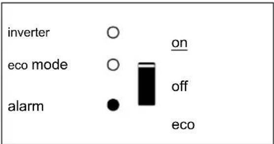
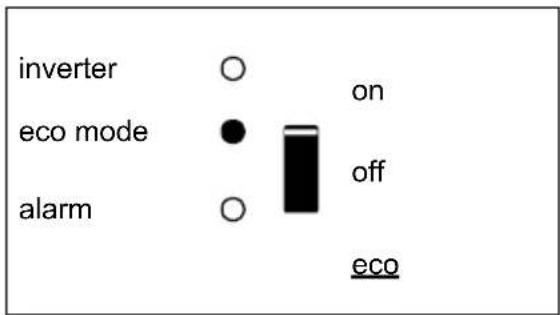
3.3 LED Indications

LED off
LED flashes
LED illuminated
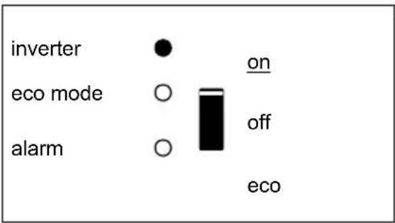
text_image
inverter eco mode alarm on off ecoThe inverter is switched on and supplies power to the load. Battery operation.
text_image
inverter eco mode alarm on off ecoThe inverter is switched on and supplies power to the load.
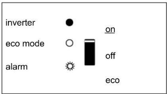
Pre alarm: overload, or battery voltage low, or inverter temperature high
text_image
inverter eco mode alarm on off ecoThe inverter is switched off. Alarm: overload, or battery voltage low, or inverter temperature high, or DC ripple voltage on battery terminal was too high.
text_image
inverter eco mode alarm on off ecoThe inverter is switched on "eco mode" and supplies power to the load.
4. INSTALLATION

This product should be installed by a qualified electrician.
4.1 Location
The product must be installed in a dry and well-ventilated area, as close as possible to the batteries. There should be a clear space of at least 10cm around the appliance for cooling.

Excessively high ambient temperature will result in the following:
Reduced service life.
Reduced charging current.
Reduced peak capacity, or shutdown of the inverter.
Never mount the appliance directly above the batteries.
The product is suitable for wall mounting. For mounting see appendix A.
The appliance can be mounted horizontally as well as vertically; vertical mounting is preferable. The vertical position offers optimum cooling.

The interior of the product must remain accessible after installation.
Try and keep the distance between the product and the battery to a minimum in order to minimize cable voltage losses.

For safety purposes, this product should be installed in a heat-resistant environment if it is used with equipment where a substantial amount of power is to be converted. You should prevent the presence of e.g. chemicals, synthetic components, curtains or other textiles, etc., in the immediate vicinity.
4.2 Connection of Battery cables
In order to fully utilize the full capacity of the product, batteries with sufficient capacity and battery cables with sufficient cross section should be used. See table.
| 24/2000 | 12/2000 | |
| Recommended cross section (mm ^2 ) | ||
| → 6 m | 50 | 70 |
| 24/2000 | 12/2000 | |
| Recommended battery capacity (Ah) | 200 – 500 | 350 – 1000 |
Remark: Internal resistance is the important factor when working with low-capacity batteries. Please consult your supplier or the relevant sections of our book “electricity on board”, downloadable from our website.
Procedure
Proceed as follows to connect the battery cables:

Use an insulated box spanner in order to avoid shorting the battery. Avoid shorting the battery cables.
Connect the battery cables: the + (red) and the - (black), to the battery see appendix A. Reverse polarity connection (+ to - and - to +) will cause damage to the product. (Safety fuse inside the Phoenix Inverter Compact can be damaged) Secure the nuts tightly in order to reduce the contact resistance as much as possible.
4.3 Connection of the AC cabling
This is a Safety Class I product (supplied with a protective grounding terminal).

The neutral wire of the AC output of this inverter is connected to the chassis.
This is to ensure proper functioning of a GFCI (or RCCB) to be installed in the AC output of the Inverter.
The chassis of the product must be connected to ground, to the frame (of a vehicle) or the ground plate or hull (of a boat).
Procedure
The terminal points are indicated clearly. From left to right: “PE” (earth), “L” (phase) and “N” (neutral).
4.4 Optional Connections
A number of optional connections are possible:
4.4.1 Remote on/off switch & remote Control panel
The product can be remotely controlled in two ways.
- With an external switch (connection terminal H, see appendix A). Operates only if the switch on the Inverter is set to "on".
- With a Phoenix Inverter Control panel (connected to one of the two RJ45 sockets C, see appendix A). Operates only if the switch on the inverter is set to "on".
Only one remote control can be connected, i.e. either a switch or a remote control panel.
4.4.2. Programmable relay
The inverters are equipped with a multi-functional relay that by default is programmed as an alarm relay. (VEConfigure3 software needed to change relay functionality).
Near the connection terminals an LED illuminates when the relay is activated (refer to S, see appendix A).
4.4.3 Parallel Connection
The inverters can be connected in parallel with several identical devices. To this end, a connection is established between the devices by means of standard RJ45 UTP cables. The system (one or more inverters plus optional control panel) will require subsequent configuration (see Section 5).
In the event of connecting inverters in parallel, the following requirements must be met:
- A maximum of six units connected in parallel.
- Only identical devices may be connected in parallel.
- The DC connection cables to the devices must be of equal length and cross-section.
- If a positive and a negative DC distribution point is used, the cross-section of the connection between the batteries and the DC distribution point must at least equal the sum of the required cross-sections of the connections between the distribution point and the inverters.
- Place the inverters close to each other, but allow at least 10 cm for ventilation purposes under, above and beside the units.
- UTP cables must be connected directly from one unit to the other (and to the remote panel).
Connection/splitter boxes are not permitted.
- Only one remote control means (panel or switch) can be connected to the system.
4.4.4 Three-phase operation
The Phoenix Inverter can also be used in 3-phase wye (Y) configuration. To this end, a connection between the devices is made by means of standard RJ45 UTP cables (the same as for parallel operation). The system (Inverters plus an optional control panel) will require subsequently configuration (see Section 5).
Pre-requisites: see Section 4.4.3.
Note: the Phoenix Inverter is not suitable for 3-phase delta ( ) configuration.
5. CONFIGURATION

Settings may only be changed by a qualified engineer.
Carefully read the instructions before changes are made.
Batteries should be placed in a dry and well-ventilated area during charging.
5.1 Standard settings: ready for use
On delivery, the Phoenix inverter is set to standard factory values. In general, these settings are suitable for stand-alone operation.
Standard factory settings
Inverter frequency 50 Hz
Inverter voltage 230 VAC
Stand-alone / parallel / 3-phase stand-alone
Search mode off
Programmable relay alarm function
5.2 Explanation of settings
Inverter frequency
Output frequency
Adjustability: 50 Hz; 60 Hz
Inverter voltage
Adjustability: 210 – 245 V
Stand-alone / parallel operation / 2-3 phase setting
Using several devices, it is possible to:
- Increase total inverter power (several devices in parallel).
- Create a split-phase system.
- Create a 3-phase system.
The standard product settings are for standalone operation. For parallel, three phase or split phase operation see section 4.4.3 and 4.4.4.
Search Mode (Applicable in stand-alone configuration only)
If search mode is “on”, the power consumption in no-load operation is decreased by approx. 70 %. In this mode the Compact, when operating in inverter mode, is switched off in case of no load or very low load, and switches on every two seconds for a short period. If the output current exceeds a set level, the inverter will continue to operate. If not, the inverter will shut down again.
The Search Mode can be set with a DIP switch.
The Search Mode "shut down" and "remain on" load levels can be set with VEConfigure3.
The standard settings are:
Shut down: 40 Watt (linear load).
Turn on: 100 Watt (linear load).
AES (Automatic Economy Switch)
Instead of the search mode, the AES mode can also be chosen (with help of VEConfigure3 only).
If this setting is turned “on”, the power consumption in no-load operation and with low loads is decreased by approx. 20 %, by slightly “narrowing” the sinusoidal voltage.
Not adjustable with DIP switches.
Applicable in stand-alone configuration only.
Programmable relay
By default, the programmable relay is set as an alarm relay, i.e. the relay will de-energise in the event of an alarm or a pre-alarm (inverter almost too hot, ripple on the input almost too high, battery voltage almost too low).
Not adjustable with DIP switches.
Near the connection terminals an LED illuminates when the relay is activated (refer to S, see appendix A).
5.3 Configuration by computer
All settings can be changed by means of a computer or with a VE.Net panel (except for the multi-functional relay and the VirtualSwitch when using VE.Net).
Some settings can be changed with DIP switches (see Section 5.2).
For changing settings with the computer, the following is required:
- VEConfigure3 software: can be downloaded free of charge at www.victronenergy.com.
- A MK3-USB (VE.Bus to USB) interface.
Alternatively, the Interface MK2.2b (VE.Bus to RS232) can be used (RJ45 UTP cable needed).
5.3.1 VE.Bus Quick Configure Setup
VE.Bus Quick Configure Setup is a software program with which one Compact unit or systems with a maximum of three Compact units (parallel or three phase operation) can be configured in a simple manner. VEConfigure3 forms part of this program.
The software free can be downloaded free of charge at www.victronenergy.com.
5.3.2 VE.Bus System Configurator
For configuring advanced applications and/or systems with four or more inverters, VE.Bus System Configurator software must be used. The software can be downloaded free of charge at www.victronenergy.com. VEConfigure3 forms part of this program.
5.4 Configuration with a VE.Net panel
To this end, a VE.Net panel and the VE.Net to VE.Bus converter are required.
With VE.Net you can set all parameters, with the exception of the multi-functional relay and the VirtualSwitch.
5.5 Configuration with DIP switches
Some settings can be changed with DIP switches
Procedure:
a) Turn the Compact on, preferably without load.
b) Set the dipswitches as required.
c) Store the settings by moving Dip switch 8 to "on" and back to "off".
5.5.1. DIP switch 1 and 2
Default setting: to operate the product with the "On/Off/Charger Only" switch ds 1: "off"
ds 2: "on"
The default setting is required when using the "On/Off/Charger Only" switch in the front panel. This setting should also be used in setups with a GX device or VE.Bus Smart dongle when no additional Digital Multi Control panel or VE.Bus BMS is connected.
When a Digital Multi Control panel or a VE.Bus BMS is included please refer to the settings below.
Setting for remote operation with a Multi Control Panel or a VE.Bus BMS:
ds 1: "on"
ds 2: "off"
This setting is required when a Multi Control Panel and/or a VE.Bus BMS is connected. The Multi Control panel must be connected to one of the two RJ45 sockets B, see appendix A.
Setting for remote operation with a 3-way switch:
ds 1: "off"
ds 2: "off"
This setting is required when a 3-way switch is connected.
The 3-way switch must be wired to terminal L, see appendix A.
Only one remote control can be connected, i.e. either a switch or a remote control panel.
In both cases the switch on the product itself should be "on".
5.5.2 Exemplary settings
Example 1 is the factory setting (since factory settings are entered by computer, all DIP switches of a new product are set to "off", except for DS-2).
| DS-1 Panel optionDS-2 Panel optionDS-3 Not usedDS-4 Not usedDS-5 FrequencyDS-6 Search modeDS-7 Not usedDS-8 Store setting | 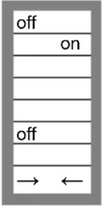 | DS-1DS-2DS-3DS-4DS-5DS-6DS-7DS-8 | 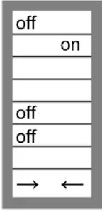 | DS-1DS-2DS-3DS-4DS-5DS-6DS-7DS-8 | 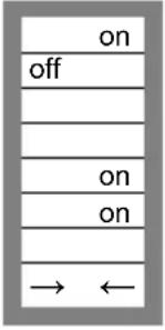 |
| Example 1: (factory setting)1 No panel connected2 No panel connected5 Frequency: 50 Hz6 Search mode off8 store setting: off→ on→ off | Example 21 No panel connected2 No panel connected5 Frequency: 50 Hz6 Search mode off8 store setting: off→ on→ off | Example 31 Panel connected2 Panel connected5 Frequency: 60 Hz6 Search mode on8 store setting: off→ on→ off | |||
Store the settings (DS3-DS7) by changing switch ds-8 from off to on, and then back to off.
The LED's “Inverter” and “eco mode” and “alarm” will flash four times to indicate acceptance of the settings.
6. MAINTENANCE
The Compact does not require specific maintenance. It will suffice to check all connections once a year. Avoid moisture and oil/soot/vapours, and keep the device clean.
7. TROUBLE SHOOTING TABLE
Proceed as follows for quick detection of common faults.
Consult your Victron Energy dealer if the fault cannot be resolved.
| Problem | Cause | Solution |
| The inverter fails to operate when switched on. | The battery voltage is too high or too low. | Ensure that the battery voltage is within the correct value. |
| The inverter fails to operate | Processor in no function-mode. | Switch Front switch off, wait 4 secondsSwitch front switch on. |
| The alarm LED flashes. | Pre-alarm alt. 1: The DC input voltage is low. | Charge the battery or check the battery connections. |
| The alarm LED flashes | Pre-alarm alt. 2: The ambient temperature is too high. | Place the inverter in a cool and well-ventilated room or reduce the load. |
| The alarm LED flashes. | Pre-alarm alt. 3: The load on the inverter is higher than the nominal load. | Reduce the load. |
| The alarm LED flashes. | Pre-alarm alt. 4: Voltage ripple on the DC input exceeds 1,25 Vrms. | Check the battery cables and terminals.Check the battery capacity; increase if necessary. |
| The alarm LED flashes intermittently. | Pre-alarm alt. 5. Low battery voltage and excessive load. | Charge the batteries, reduce the load or install batteries with a higher capacity. Use shorter and/or thicker battery cables. |
| The alarm LED is on | The inverter did cut out following a pre-alarm. | Check the table for the appropriate course of action. |
8. TECHNICAL DATA
| Phoenix Inverter | C 12/2000 230 V | C 24/2000 230 V |
| INVERTER | ||
| Input voltage range (VDC) | 9,5 – 17 V | 19 – 33 V |
| Output | Output voltage: 230 VAC ± 2 %Frequency: 50 Hz ± 0,1 % (1) | |
| Cont. output power at 25 °C (VA) (3) | 2000 | 2000 |
| Cont. output power at 25 °C (W) | 1600 | 1600 |
| Cont. output power at 40 °C (W) | 1450 | 1450 |
| Cont. output power at 65 °C (W) | 1000 | 1000 |
| Peak power (W) | 3500 | 3500 |
| Maximum efficiency (%) | 92 | 92 |
| Zero-load power (W) 9 11 | ||
| Zero load power in search mode (W) 3 4 | ||
| GENERAL | ||
| Programmable relay (4) | yes | |
| Protection (2) | a - g | |
| Common Characteristics | Operating temp. range: -40 to +65 °C (fan assisted cooling) Humidity (non condensing): max 95% | |
| ENCLOSURE | ||
| Common Characteristics | Material & Colour: aluminium (blue RAL 5012)Protection category: IP 21 | |
| Battery-connection | Bolts M8 | |
| 230 VAC-connection | connector 6 mm2, 10 AWG | |
| Weight (kg) | 12 | |
| Dimensions (hxwxd in mm) | 520 x 255 x 125 | |
| STANDARDS | ||
| Safety | EN 60335-1, EN 60335-2-29 | |
| Emission / Immunity | EN 55014-1, EN 55014-2, EN 61000-3-3 | |
1) Can be adjusted to 60 Hz and to 240 V
2) Protection
a) Output short circuit
b) Overload
c) Battery voltage too high
d) Battery voltage too low
e) Temperature too high
f) 230 VAC on inverter output
g) Input voltage ripple too high
3) Non linear load, crest factor 3:1
4) Programmable relay which can be set for general alarm, DC undervoltage or genset start signal function
1. VEILIGHEIDSVOORSCHRIFTEN
Algemeen
text_image
inverter eco mode alarm on off ecotext_image
inverter on eco mode off alarm ecotext_image
inverter eco mode alarm on off ecotext_image
inverter eco mode alarm on off ecoStand alone / parallel operation
AES (Automatic Economy Switch)
text_image
inverter on eco mode off alarm ecotext_image
inverter eco mode alarm on off ecotext_image
inverter eco mode alarm on off ecotext_image
inverter eco mode alarm on off eco4.4 Optionale Anschlüsse
- Create a split-phase system.
AES (Automatic Economy Switch)
AES (Automatic Economy Switch)
text_image
inverter eco mode alarm on off ecotext_image
inverter eco mode alarm on off ecotext_image
inverter eco mode alarm on off ecotext_image
inverter eco mode alarm on off ecoAppendix A: overview connections
Appendix A: overview connections
Appendix B: installation information
flowchart
graph TD
    A["Installation information"] --> B["Phoenix Multi Compact chassis"]
    B --> C["output Neutral to PE connection"]
    C --> D["DC fuse"]
    D --> E["Converter"]
    E --> F["To battery"]
    G["F connected to chassis"] --> H["E output"]
    I["L Chassis on output"] --> J["Ground terminals should be permanently connected to ground"]
    K["N"] --> L["Output"]
    M["PE"] --> N["Output"]
    O["L"] --> P["Ground"]
    Q["J"] --> R["Power supply"]
This ground wire "G" connects the output neutral to ground. It must be cut/removed if a floating output is required or reposition to "dummy" terminal.
text_image
J51 TO J101 G BLUE BROWN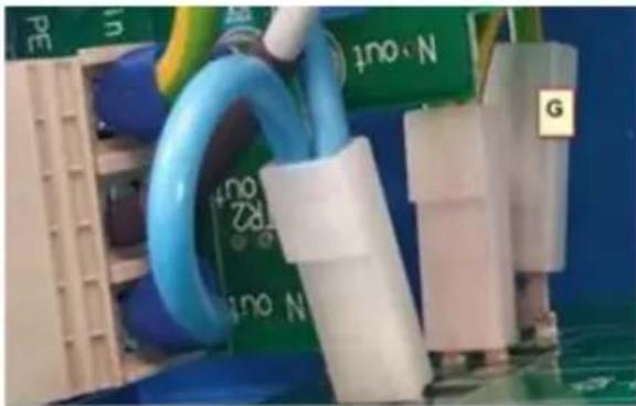
natural_image
Close-up of electronic components including capacitors and connectors with visible labels (no readable text or symbols)dummy
| EN | NL | FR | |
| E | Output | Uitgang | Sortie |
| F | Connected to chassis | Aardverbinding naar behuizing | Liaison à la terre du boîtier |
| G | Output Neutral to PE connection | Uitgangs Nul met Aarde verbindingsdraadje | Liaison du neutre de sortie à PE |
| I | DC fuse | DC zekering | Fusible DC |
| J | Converter | omvormer | Convertisseur |
| L | Chassis on output ground terminals should be permanently connected to ground | Behuizing moet permanent met de aarde zijn verbonden | Mise à la terre permanente du boîtier |
| DE | ES | IT | |
| E | Verbracherausgang | Salida | Uscita |
| F | Verbindung Landstromerde / gehäuse | Conexión a tierra de la carcasa | Ingresso e uscita di terra collegati al telaio |
| G | Schutzleiter PE (ERDUNG) Anschlüsse | Salida de conexión de neutro a PE | Collegamento uscita neutro a PE |
| I | ANL-Gleichstrom-sicherung | Fusible CC | Fusibile CC |
| J | Wandler verbindung | Conversor | Convertitore |
| L | Schutzerdungs-anschluss am Gehäuse, muss mit dem Chassis eines Fahrzeugs oder dem Erdungspunkt eines Bootes verbunden sein. | Puesta a tierra permanente de la carcasa | Il telaio in corrispondenza dei morsetti di ingresso/uscita di terra dovrebbe essere sempre messo a terra |
Appendix C: parallel connection
text_image
Panel Master Unit 1 Bat+ Bat- GND Slave Unit 2 Bat+ Bat- GND Slave Unit 3 Bat+ Bat- GND PE OUT AC OUT N AC OUT L1Appendix D: three-phase connection
PO Box 50016 | 1305 AA Almere | The Netherlands
: sales@victronenergy.com
www.victronenergy.com