Phoenix 250VA - Power inverter VICTRON ENERGY - Free user manual and instructions
Find the device manual for free Phoenix 250VA VICTRON ENERGY in PDF.
User questions about Phoenix 250VA VICTRON ENERGY
0 question about this device. Answer the ones you know or ask your own.
Ask a new question about this device
Download the instructions for your Power inverter in PDF format for free! Find your manual Phoenix 250VA - VICTRON ENERGY and take your electronic device back in hand. On this page are published all the documents necessary for the use of your device. Phoenix 250VA by VICTRON ENERGY.
USER MANUAL Phoenix 250VA VICTRON ENERGY
Phoenix Inverter VE.Direct
12 | 250 12 | 375 12 | 500 12 | 800 12 | 1200
24 | 250 24 | 375 24 | 500 24 | 800 24 | 1200
48 | 250 48 | 375 48 | 500 48 | 800 48 | 1200
1. IMPORTANT SAFETY INSTRUCTIONS – SAVE THESE INSTRUCTIONS!
In general
Please read the documentation supplied with this product first, so that you are familiar with the safety signs en directions before using the product. This product is designed and tested in accordance with international standards. The equipment should be used for the designated application only.
Warning – These servicing instructions are for use by qualified personnel only. To reduce the risk of electric shock, do not perform any servicing other than that specified in the operating instructions unless you are qualified to do so.
WARNING: ELECTRIC SHOCK HAZARD
The product is used in conjunction with a permanent energy source (battery). Input and/or output terminals may still be dangerously energized, even when the equipment is switched off. Always disconnect the battery before carrying out maintenance or servicing the product.
The product has no internal user-serviceable components. Do not remove the front plate or operate the product if any panels have been removed. All servicing must be undertaken by qualified personnel.
Please read the installation instructions in the installation manual before installing the equipment.
This is a Safety Class I product (supplied with a protective grounding terminal). The chassis must be grounded. A grounding point is located on the outside of the product. Whenever it is likely that the grounding protection has been damaged, the product must be turned off and secured against unintended operation; please contact qualified service staff.
The AC output is isolated from the DC input and the chassis unless the unit is equipped with a Ground Fault Circuit Interrupter (GFCI). Units with a GFCI have AC output neutral connected to chassis inside the device by default. A qualified installer should check this connection since it is necessary for the GFCI to function properly. Local regulations may require a true neutral. In this case one of the AC output wires must be connected to the chassis, and the chassis must be connected to a reliable ground. Please note that a true neutral is needed to ensure correct operation of an earth leakage circuit breaker.
Ensure that the equipment is used under the correct ambient conditions. Never operate the product in a wet or dusty environment. Never use the product where there is a risk of gas or dust explosions.
Ensure there is adequate free space (10 cm) for ventilation around the product and check that the ventilation vents are not blocked.
This appliance is not intended for use by persons (including children) with reduced physical, sensory or mental capabilities, or lack of experience and knowledge, unless they have been given supervision or instruction concerning use of the appliance by a person responsible for their safety.
Children should be supervised to ensure that they do not play with the appliance.
Use of an attachment not recommended or sold by the marine unit manufacturer may result in a risk of fire, electric shock, or injury to persons.
2. Description
VE.Direct communication port
The VE.Direct port can be connected to:
- A computer (VE.Direct to USB interface cable needed)
- Apple and Android smartphones, tablets and other devices (VE.Direct to Bluetooth Smart dongle needed)
Fully configurable
• Low battery voltage alarm trip and reset levels
- Low battery voltage cut-off and restart levels, or Dynamic Cut-off
• Output voltage 210 - 245 V
• Frequency 50 Hz or 60 Hz
• ECO mode on/off and ECO mode sense level
Monitoring
Battery voltage, AC Output voltage, load indicator, alarms
Proven reliability
The full bridge with toroidal transformer topology has proven its reliability over many years. The inverters are short circuit proof and protected against overheating, whether due to overload or high ambient temperature.
High start-up power
Needed to start loads such as power converters for LED lamps, filament lamps or electric tools.
ECO mode
When in ECO mode, the inverter will switch to standby when the load decreases below a preset value. It will switch on and check every few seconds, adjustable, if the load has increased again.
Remote on/off connector
A remote on/off switch can be connected to a two-pole connector or between battery plus and the left hand contact of the two pole connector.
LED diagnosis
A red and a green LED indicate inverter operation and status of the different protections.
To transfer the load to another AC source: the automatic transfer switch
For our low power inverters we recommend our Filax Automatic Transfer Switch. The Filax features a very short switchover time (less than 20 milliseconds) so that computers and other electronic equipment will continue to operate without disruption.
Available with different output sockets
Schuko, UK (BS-1363), AU/NZ (3112) or IEC-320 (male plug included)
3. Installation
3.1 Location of the inverter
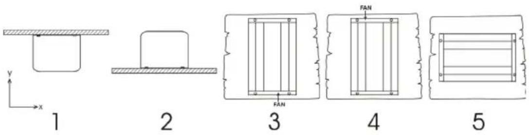
text_image
1 2 3 4 51 Ceiling mounting (inverted).
Not recommended
- Base mounting.
OK
3 Vertical wall mounting, fan at bottom.
OK (beware of small objects falling through the ventilation openings on top).
4 Vertical wall mounting, fan on top.
Not recommended
5 Horizontal wall mounting.
OK
For best operating results, the inverter should be placed on a flat surface. To ensure a trouble free operation of the inverter, it must be used in locations that meet the following requirements:
a) Avoid any contact with water. Do not expose the inverter to rain or moisture.
b) Do not place the unit in direct sunlight. Ambient air temperature should be between -20 °C and 40 °C (humidity < 95 % non condensing). Note that in extreme situations the inverter's case temperature can exceed 70 °C.
c) Do not obstruct the airflow around the inverter. Leave at least 10 centimetres clearance around the inverter. When the inverter is running too hot, it will shut down. When the inverter has reached a safe temperature level the unit will automatically restart again.
3.2 Connection to the battery
In order to utilize the full capacity of the product, batteries with sufficient capacity and battery cables with sufficient cross section should be used. See table:
| 12/250 | 24/250 | 48/250 | 12/375 | 24/375 | 48/375 | ||
| Minimum battery cap. | 30 Ah | 20 Ah | 10 Ah | 40 Ah | 30 Ah | 15 Ah | |
| Internal DC fuse | 2 x 30 A | 30 A | 25 A | 2 x 40 A | 40 A | 25 A | |
| Fuse type (Mfr.: Littelfuse) | ATOF 32 V | ATOF 32 V | FKS 80 V | ATOF 32 V | ATOF 32 V | FKS 80 V | |
| Fuse replaceable | no | no | no | no | no | no | |
| Recommended DC cable cross-section ( mm^2 ) | |||||||
| 0 – 1,5 m | 4 mm^2 | 2,5 mm^2 | 1,5 mm^2 | 6 mm^2 | 4 mm^2 | 2,5 mm^2 | |
| 1,5 – 3 m | 6 mm^2 | 4 mm^2 | 2,5 mm^2 | 10 mm^2 | 6 mm^2 | 4 mm^2 | |
| 12/500 | 24/500 | 48/500 | 12/800 | 24/800 | 48/800 | ||
| Minimum battery cap. | 60 Ah | 40 Ah | 20 Ah | 100 Ah | 50 Ah | 30 Ah | |
| Internal DC fuse | 3 x 35 A | 2 x 25 A | 30 A | 125 A | 2 x 40 A | 2 x 20 A | |
| Fuse type (Mfr.: Littelfuse) | ATOF 32 V | ATOF 32 V | FKS 80 V | MIDI 32 V | ATOF 32 V | FKS 80 V | |
| Fuse replaceable | no | no | no | yes | no | no | |
| Recommended DC cable cross-section ( mm^2 ) | |||||||
| 0 – 1,5 m | 6 mm^2 | 6 mm^2 | 4 mm^2 | 16 mm^2 | 6 mm^2 | 4 mm^2 | |
| 1,5 -3 m | 10 mm^2 | 10 mm^2 | 6 mm^2 | 25 mm^2 | 10 mm^2 | 6 mm^2 | |
| 12/1200 | 24/1200 | 48/1200 | |
| Minimum battery cap. | 150 Ah | 60 Ah | 30 Ah |
| Internal DC fuse | 200 A | 100 A | 50 A |
| Fuse type (Mfr.: Littelfuse) | MIDI 32 V | MIDI 32 V | MIDI 58 V |
| Fuse replaceable | yes | yes | yes |
| 0 – 1,5 m | 25 mm ^2 | 10 mm ^2 | 6 mm ^2 |
| 1,5 -3 m | 35 mm ^2 | 16 mm ^2 | 10 mm ^2 |
The inverters are fitted with an internal DC fuse (see table above for rating). If the DC cable length is increased to more than 1,5m, an additional fuse or DC circuit breaker must be inserted close to the battery. Important note: for UL certified (NEMA GFCI) inverters it is mandatory to install a fuse or DC circuit breaker close to the battery, even if the cable length is less than 1,5m.
Reverse polarity connection of the battery wires will blow the internal fuse and can damage the inverter. The internal fuse is not always replaceable (see table above).
3.3 Wire size for connecting the inverter chassis to ground
The earth conductor from the earth lug on the chassis to ground should have at least half the cross-section of the conductors used for the battery connection: see Appendix B.
3.4 Connection to the load
Never connect the output of the inverter to another AC source, such as a household AC wall outlet or a generator.
The inverter does not have a fuse in the AC output. The AC cabling is protected by a fast-acting current limiter in case of a short circuit and an overload detection mechanism which mimics the characteristics of a fuse (i.e. faster shutdown with larger overload). It is important to size your wiring properly based on the inverters' power rating.
3.5 Connecting the inverter neutral output to the chassis/ground
The AC output is isolated from the DC input and the chassis. Local regulations may require a true neutral. In this case one of the AC output wires must be connected to the chassis, and the chassis must be connected to a reliable ground: see appendix A.
3.6 Remote on/off connector
A remote on/off switch can be connected to the two-pole connector. Alternatively, the left-hand contact of the connector can be switched to battery positive: useful in automotive applications, wire it to the ignition contact.
Note that also the front switch needs to set to either On or ECO for the inverter to start.
3.7 Configuration
The inverter is ready for use with the factory settings (see specifications), and can be configured with a computer (VE.Direct to USB interface cable needed), Apple and Android smartphones, tablets and other devices (VE.Direct to Bluetooth Smart dongle needed).
4. Operation
4.1 LED definitions
| Green LED | Status | Trouble shooting |
| ●●●●●●●●Solid on | Inverter on | Red LED Offstatus OKRed LED On or blinking:The Inverter is still on, but will shut down when the condition gets worse. See red LED table for warning reason |
| ●●———Slow single pulse | ECO mode | If the inverter keeps switching on and off while there is a load connected, the load may be too small compared to the actual ECO mode settings. Increase the load or change ECO mode settings. (minimum ECO mode setting: 15 W) |
| ●—●———Fast double pulse | Off and waiting | Inverter did shut down because of a protection. The inverter will restart automatically as soon as all alarm conditions are cleared. See red LED state for the shutdown reason. |
| —————Off | Inverter off | Red LED OffCheck the On/Off/ECO switch: it should be in On position or in ECO position.Check Remote on/off connector.Check DC cable connections and fuses.Inverter fuse blown: the inverter has to be returned for service.Red LED On or blinkingThe inverter did shut down because of a protection. It will no longer automatically restart. The red LED indicates the reason for shutdown. Remove the cause and then restart the inverter by switching it Off, and then back On. |
| Red LED | Definition | Trouble shooting | |
| ●●●●●●●●● | Solid on | Overload | Reduce load |
| ●●●●---- | Slow blink | Low batt. | Recharge or replace batteryCheck DC cable connectionsCheck cable cross section as it may be insufficient.See section 4.3 Protections and automatic restarts for manual and automatic restart behavior. |
| ●-●-●-●- | Fast blink | High batt. | Reduce DC input voltage, check for faulty charger |
| ●-●---- | Double pulse | High temp. | Reduce load and/or move inverter to better ventilated area |
| ●----●---- | Fast single pulse | High DC ripple | Check DC cable connections and cable cross section. |
4.2 ECO Mode
Set the front switch to ECO mode to reduce the power consumption in no-load operation. The inverter will automatically switch off as soon as it detects that there is no load connected. It then switches on, briefly, every 2.5 seconds to detect a load. If the output power exceeds the set level, the inverter will continue to operate.
The default ECO mode wake-up minimum power is 15 Watt.
The default ECO mode search interval is 2.5 seconds
Note that the required ECO mode settings are heavily dependent on the type of load: inductive, capacitive, non-linear. Adjustment may be needed.
4.3 Protections and automatic restarts
Overload
Some loads like motors or pumps draw large inrush currents in a start-up situation. In such circumstances, it is possible that the start-up current exceeds the over current trip level of the inverter. In this case the output voltage will quickly decrease to limit the output current of the inverter. If the over current trip level is continuously exceeded, the inverter will shut down: wait 30 seconds and then restart.
After three restarts followed by another overload within 30 seconds of restarting, the inverter will shutdown and remain off. The LEDs will signal shutdown due to overload. To restart the inverter, switch it Off, then On.
Low battery voltage (adjustable)
The inverter will shut down when the DC input voltage drops below the low battery shutdown level. After a minimum delay of 30 seconds, the inverter will restart if the voltages rise above the low battery restart level.
After three restarts followed by a low battery shutdown within 30 seconds of restarting, the inverter will shutdown and stop retrying. The LEDs will signal low battery shutdown. To restart the inverter, switch it Off, and then On, or recharge the battery: as soon as the battery has risen and then stays above the Charge detect level for 30 seconds, it will switch on.
See the Technical Data table for default low battery shutdown and restart levels. They can be changed with VictronConnect (computer or app).
Alternatively Dynamic Cut-off can be implemented, see
https://www.victronenergy.com/live/ve.direct:phoenix-inverters-dynamic-cutoff
High battery voltage
Reduce DC input voltage and/or check for a faulty battery- or solar-charger in the system. After shutting down due to a high battery voltage, the inverter will first wait 30 seconds and then retry operation as soon as the battery voltage has dropped to acceptable level. The inverter will not stay off after multiple retries.
High temperature
A high ambient temperature or enduring high load may result in shut down to over temperature.
The inverter will restart after 30 seconds. The inverter will not stay off after multiple retries.
Reduce load and/or move inverter to better ventilated area.
High DC ripple
High DC ripple is usually caused by loose DC cable connections and/or too thin DC wiring. After the inverter has switched off due to high DC ripple voltage, it waits 30 seconds and then restarts.
After three restarts followed by a shutdown due to high DC ripple within 30 seconds of restarting, the inverter will shutdown and stops retrying. To restart the inverter, switch it Off and then On.
Continuous high DC ripple reduces life expectancy of the inverter.
- Technical data
| Phoenix Inverter | 12 Volt | 12/250 | 12/375 | 12/500 | 12/800 |
| 24 Volt | 24/250 | 24/375 | 24/500 | 24/800 | |
| 48 Volt | 48/250 | 48/375 | 48/500 | 48/800 | |
| Cont. power at 25 °C (1) | 250 VA | 375 VA | 500 VA | 800 VA | |
| Cont. power at 25 °C / 40 °C | 200 / 175 W | 300 / 260 W | 400 / 350 W | 650 / 560 W | |
| Peak power | 400 W | 700 W | 900 W | 1500 W | |
| Output AC voltage / frequency (adjustable) | 230 VAC or 120 VAC +/- 3 % 50 Hz or 60 Hz +/- 0.1 % | ||||
| Input voltage range | 9.2 - 17 / 18.4 - 34.0 / 36.8 - 62.0 VDC | ||||
| Low battery shut down (adjustable) | 9.3 / 18.6 / 37.2 VDC | ||||
| Low battery restart & alarm (adjustable) | 10.9 / 21.8 / 43.6 VDC | ||||
| Battery charged detect (adjustable) | 14.0 / 28.0 / 56.0 VDC | ||||
| Max. efficiency | 87/88/88 % | 89/89/90 % | 90/90/91 % | 90/90/91 % | |
| Zero-load power | 4.2/5.2/7.9 W | 5.6/6.1/8.5 W | 6/6.5/9 W | 6.5/7/9.5 W | |
| Default zero-load power in ECO mode (default search interval: 2.5 s, adjustable) | 0.8/1.3/2.5 W | 0.9/1.4/2.6 W | 1 / 1.5 / 3 W | 1 / 1.5 / 3 W | |
| ECO mode stop and start power setting | Adjustable | ||||
| Protection (2) | a - f | ||||
| Operating temperature range | -40 to +60 °C (fan assisted cooling)(derate 1.25 % per °C above 40 °C) | ||||
| Humidity (non-condensing) | max 95 % | ||||
| ENCLOSURE | |||||
| Material & Colour | Steel chassis and plastic cover (blue Ral 5012) | ||||
| Battery-connection | Screw terminals | ||||
| Maximum cable cross-section | 10 mm2 / AWG8 | 25/10/10 mm2 / AWG4/8/8 | |||
| Standard AC outlets | 230 V: Schuko (CEE 7/4), IEC-320 (male plug included)UK (BS 1363), AU/NZ (AS/NZS 3112)120 V: Nema5-15R, NEMA GFCI (2x Nema5-15R with GFCI) | ||||
| Protection category | IP 21 | ||||
| Weight | 2.4 kg/5.3 lbs | 3.0 kg/6.6 lbs | 3.9 kg/8.5 lbs | 5.5 kg/12 lbs | |
| Dimensions (hxwxd, mm)(hxwxd, inch) | 86x165x2603.4x6.5x10.2 | 86x165x2603.4x6.5x10.2 | 86x172x2753.4x6.8x10.8 | 105x216x3054.1x8.5x12.1(12 V model:105x230x325) | |
| ACCESSORIES | |||||
| Remote on-off | Yes | ||||
| Automatic transfer switch | Filax or Multi | ||||
| STANDARDS | |||||
| Safety | EN/IEC 60335-1 / EN/IEC 62109-1 / UL 458 (3) | ||||
| EMC | EN 55014-1 / EN 55014-2IEC 61000-6-1 / IEC 61000-6-3 | ||||
| Automotive Directive | ECE R10-4 EN 50498 | ||||
| 1) Nonlinear load, crest factor 3:12) Protection key:a) output short circuitb) overloadc) battery voltage too highd) battery voltage too lowe) temperature too highf) DC ripple too high | 3) UL 458 only for inverters with GFCI output socket | ||||
5. Technical data, continued
| Phoenix Inverter | 12 Volt | 12/1200 |
| 24 Volt | 24/1200 | |
| 48 Volt | 48/1200 | |
| Cont. power at 25 °C (1) | 1200 VA | |
| Cont. power at 25 °C / 40 °C | 1000 / 900 W | |
| Peak power | 2200 W | |
| Output AC voltage / frequency (adjustable) | 230 VAC or 120 VAC +/- 3 % 50 Hz or 60 Hz +/- 0.1 % | |
| Input voltage range | 9.2 - 17 / 18.4 - 34.0 / 36.8 - 62.0 VDC | |
| Low battery shut down (adjustable) | 9.3 / 18.6 / 37.2 VDC | |
| Low battery restart & alarm (adjustable) | 10.9 / 21.8 / 43.6 VDC | |
| Battery charged detect (adjustable) | 14.0 / 28.0 / 56.0 VDC | |
| Max. efficiency | 92 / 94 / 94 % | |
| Zero-load power | 8 / 9.5 / 10 W | |
| Default zero-load power in ECO mode (default search interval: 2.5 s, adjustable) | 1 / 1.7 / 2.7 W | |
| ECO mode stop and start power setting | Adjustable | |
| Protection (2) a - f | ||
| Operating temperature range | -40 to +60 °C (fan assisted cooling)(derate 1.25 % per °C above 40 °C) | |
| Humidity (non-condensing) | max 95 % | |
| ENCLOSURE | ||
| Material & Colour | Steel chassis and plastic cover (blue Ral 5012) | |
| Battery-connection | Screw terminals | |
| Maximum cable cross-section | 35/25/25 mm2 / AWG2/4/4 | |
| Standard AC outlets | 230 V: Schuko (CEE 7/4), IEC-320 (male plug included)UK (BS 1363), AU/NZ (AS/NZS 3112)120 V: Nema5-15R, NEMA GFCI (2x Nema5-15R with GFCI) | |
| Protection category | IP 21 | |
| Weight | 7.7 kg/17 lbs | |
| Dimensions (hxwxd, mm)(hxwxd, inch) | 117x232x3274.6x9.1x12.9(12 V model: 117x232x367) | |
| ACCESSORIES | ||
| Remote on-off Yes | ||
| Automatic transfer switch Filax or Multi | ||
| STANDARDS | ||
| Safety | EN/IEC 60335-1 / EN/IEC 62109-1 / UL 458 (3) | |
| EMC | EN 55014-1 / EN 55014-2IEC 61000-6-1 / IEC 61000-6-3 | |
| Automotive Directive | ECE R10-4 EN 50498 | |
| 1) Nonlinear load, crest factor 3:12) Protection key:a) output short circuitb) overloadc) battery voltage too highd) battery voltage too lowe) temperature too highf) DC ripple too high | 3) UL 458 only for inverters with GFCI output socket | |
Fig 1: Front and rear view
Example of front view:
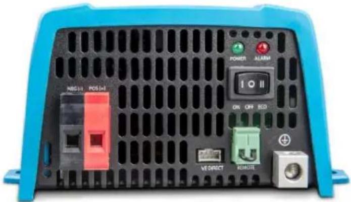
text_image
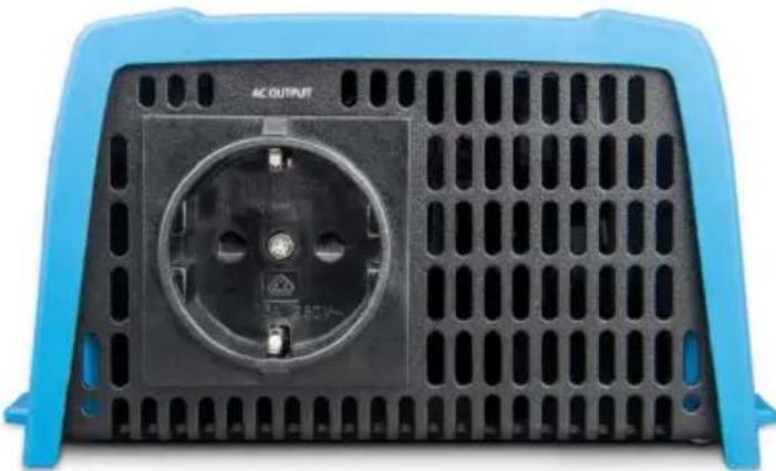
POWER ALARM NEG (+) POS (+) ON OFF RED VT DIRECT ROUTEExample of rear view with Schuko outlet:
natural_image
Front view of a black electrical socket with ventilation grilles and a blue plastic cover (no text or symbols visible)Example of rear view with NEMA GFCI outlet:
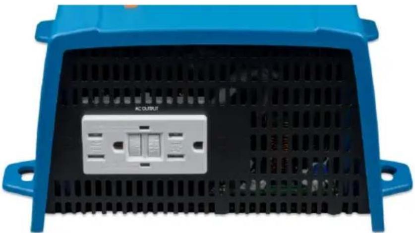
natural_image
Front view of a blue industrial control panel with ventilation grilles and a labeled output port (no readable text beyond label)Mounting instructions
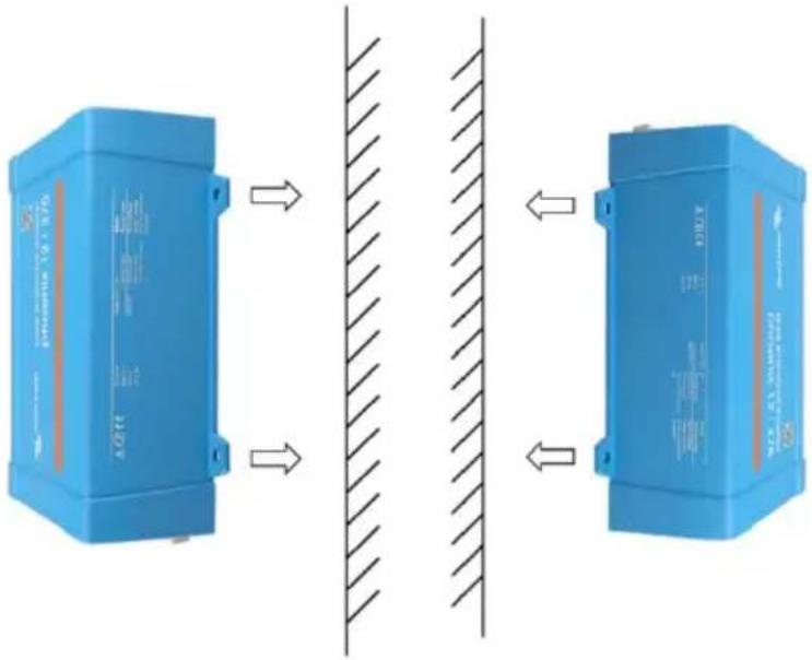
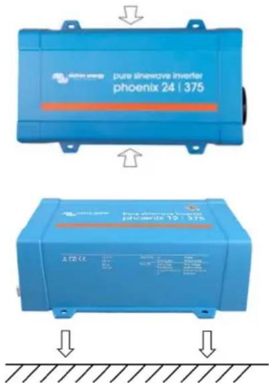
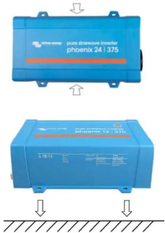
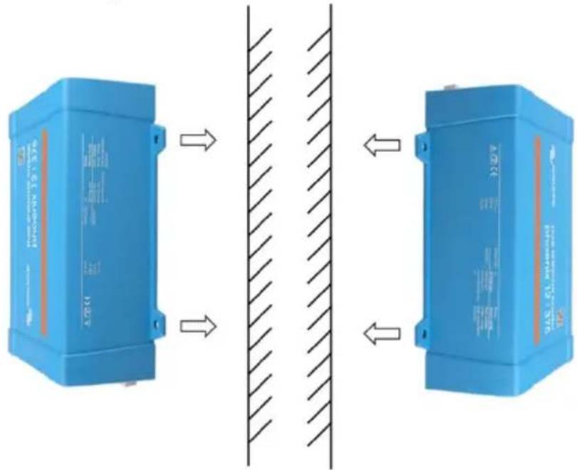
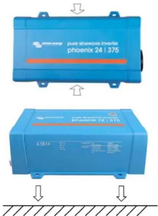
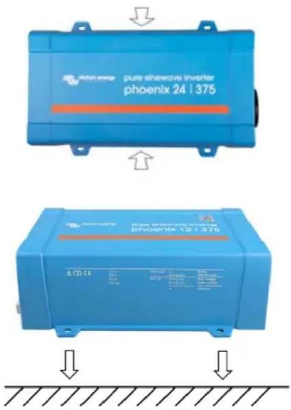
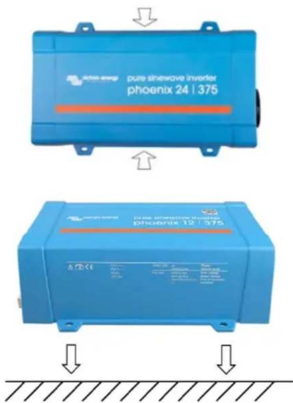
text_image
Diagram showing two blue industrial control units with labeled components and directional arrows indicating flow or interaction between them.Figure 1
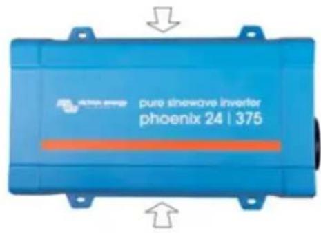
text_image
pure snowwave inverter phoenix 24 | 375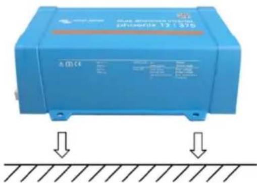
text_image
blue electrochemical system phoenix 12 : 375Figure 2
Mount the inverter with four screws vertically up- or downwards or horizontally up- or downwards (as indicated in Figure 1) against a sturdy wall or horizontally on a suitable ground surface (as indicated in Figure 2). Keep at least 4 inches (10 cm) clearance with respect to other apparatus/objects. Beware that IP21 only applies to the lower mounting method depicted in Figure 2; otherwise IP20 is applies. Do not mount the inverter upside down to a surface.
Appendix A
Connecting the inverter neutral output to the chassis/ground
The AC output is isolated from the DC input and the chassis. Local regulations may require a true neutral. In this case one of the AC output wires must be connected to the chassis, and the chassis must be connected to a reliable ground. Inside the inverter a provision has been made to be able to connect the neural and the chassis; the way to do this is explained below.
Please be sure to disconnect the battery when connecting the neutral to protective earth (PE).
An internal PE wire, which is used to connect the neutral and the chassis, is accessible after removing the plastic cover. A Torx T10 screwdriver is needed to loosen the four screws which hold the plastic cover.
In the pictures below the two possible connections of the PE wire are shown:
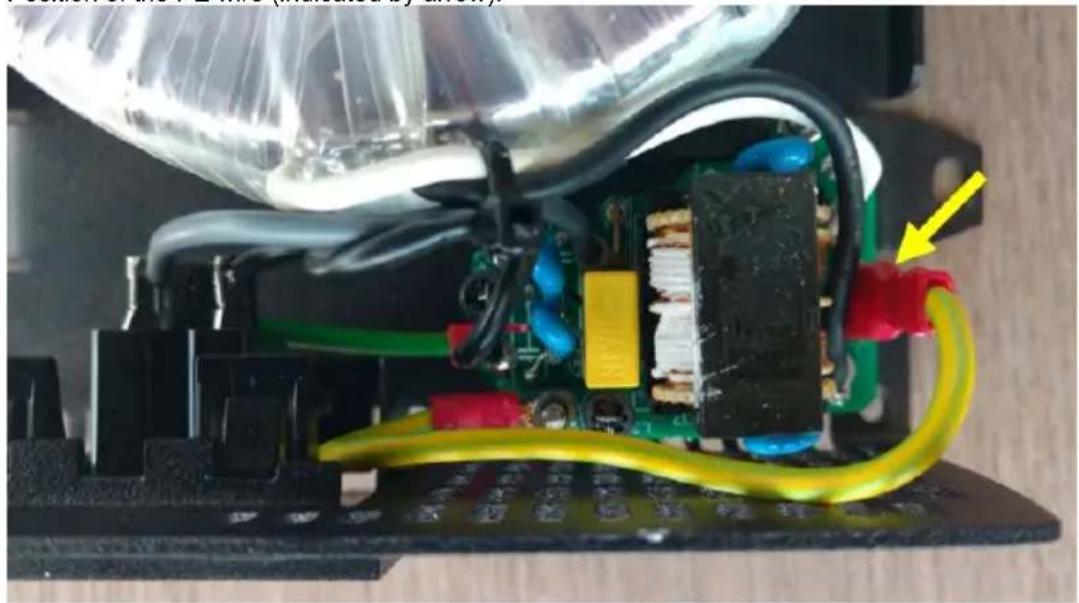
For the 250 VA, 375 VA and 500 VA inverters:
1. Neutral floating
Position of the PE wire (indicated by arrow):
natural_image
Close-up of an electronic circuit board with visible wiring and components, no text or symbols present.2. Neutral connected to protective earth
Position of the PE wire (indicated by arrow):
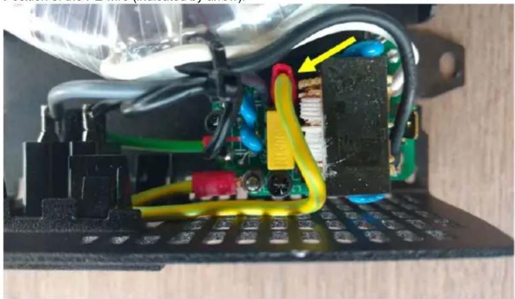
natural_image
Close-up of an electronic circuit board with visible traces, wires, and components (no text or symbols)For the 800 VA and 1200 VA inverters:
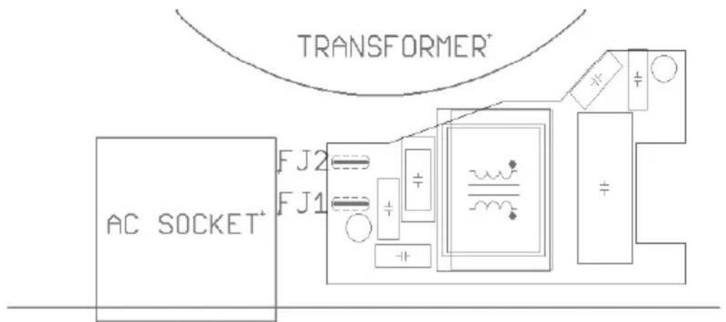
For these inverters the earth wire from the chassis can be either connected to FJ1 (neutral floating) or to FJ2 (neutral connected to earth/chassis). The labels FJ1 and FJ2 are printed on the circuit board. The default position is FJ1, i.e. neutral is floating.
text_image
TRANSFORMER+ AC SOCKET+ FJ2 FJ1Earth wire on FJ1: neutral floating Earth wire on FJ2: neutral connected to earth
Appendix B
Wire size for connecting the inverter chassis to ground
The earth conductor from the earth lug on the chassis to ground should have at least half the cross-section of the conductors used for the battery connection. The maximum conductor size that fits the earth lug is 25 mm^2 . Use the table below to find the correct cross-section for the earth conductor.
| Cable cross-section | |
| to battery | to protective earth |
| 1.5 mm2 | ≥ 0.75 mm2 |
| 2.5 mm2 | ≥ 1.5 mm2 |
| 4 mm2 | ≥ 2.5 mm2 |
| 6 mm2 | ≥ 4 mm2 |
| 10 mm2 | ≥ 6 mm2 |
| 16 mm2 | ≥ 10 mm2 |
| 25 mm2 | ≥ 16 mm2 |
| 35 mm2 | 25 mm2 |
1. BELANGRIJKE VEILIGHEIDSINSTRUCTIES – BEWAAR DEZE INSTRUCTIES!
In het algemeen
natural_image
Front view of a black electrical socket mounted on a blue plastic panel (no text or symbols visible)natural_image
Front view of a blue industrial control panel with ventilation grilles and a central AC output indicator (no readable text or symbols beyond branding)text_image
Diagram showing two blue industrial control units with labeled components and directional arrows indicating flow or movement between them.Afbeelding 1
text_image
pure sinewave inverter phoenix 24 | 375 A.100 CE 1000Ω 10Ω 10Ω 10Ω 10Ω 10Ω 10Ω 10Ω 10Ω 10Ω 10Ω 10Ω 10Ω 10Ω 10Ω 10Ω 10Ω 10Ω 10Ω 10Ω 10Ω 10Ω 10Ω 10Ω 10Ω 10Ω 8.5V 8.5V 8.5V 8.5V 8.5V 8.5V 8.5V 8.5V 8.5V 8.5V 8.5V 8.5V 8.5V 8.5V 8.5V 8.5V 8.5V 8.5V 8.5V 8.5V 8.5M 8.5M 8.5M 8.5M 8.5M 8.5M 8.5M 8.5M 8.5M 8.5M 8.5M 8.5M 8.5M 8.5M 8.5M 8.5M 8.5M 8.5M 8.5MAfbeelding 2
natural_image
Close-up of an electronic circuit board with visible wiring and components, no text or symbols present.natural_image
Close-up of an electronic circuit board with visible wiring, components, and a yellow arrow pointing to a component (no text or symbols)Earth wire on FJ1: neutral floating Earth wire on FJ2: neutral connected to earth
Bijlage B
Port de communication VE.Direct
natural_image
Front view of a black electrical outlet with ventilation grilles and a circular socket, mounted on a blue plastic frame (no text or symbols visible)natural_image
Front view of a blue industrial electrical connector panel with ventilation grilles and a central AC output button (no readable text beyond label)text_image
Diagram showing two blue industrial control units with labeled components and directional arrows indicating flow or interaction between them.Illustration 1
text_image
pure sinewave inverter phoenix 24 | 375 pure sinewave inverter phoenix 12 | 375Illustration 2
natural_image
Close-up of an electronic circuit board with exposed components and colored wires, no visible text or symbolsnatural_image
Close-up of an electronic circuit board with visible wiring and components, no text or symbols present.Earth wire on FJ1: neutral floating
Earth wire on FJ2: neutral connected to earth
Annexe B
natural_image
Front view of a black electrical socket with ventilation grilles and a blue plastic cover (no text or symbols visible)natural_image
Front view of a blue industrial electronic device with ventilation grilles and a central AC output port (no text or symbols visible)Montageanleitung
text_image
Diagram showing two blue electronic devices with labeled components and directional arrows, likely illustrating a physical or engineering concept.Abbildung 1
text_image
puro sinewave invertor phoenix 24 | 375 PUBS SINEWAVE INVERTOR phoenix 19 | 375Abbildung 2:
natural_image
Close-up of an electronic circuit board with visible wiring and components, no text or symbols present.natural_image
Close-up of an electronic circuit board with visible wiring, capacitors, and components (no text or symbols)Earth wire on FJ1: neutral floating Earth wire on FJ2: neutral connected to earth
Anhang B
Conector on/off remoto
3.6 Conector On/Off remoto
natural_image
Front view of a black electrical socket with ventilation grilles and a blue plastic cover (no text or symbols visible)natural_image
Front view of a blue and black electronic device casing with ventilation grilles and a labeled AC output panel (no readable text beyond label)text_image
Diagram showing two blue industrial control units with directional arrows indicating flow or movement between them, separated by a hatched boundary.Figura 1
text_image
pure sinewave inverter phoenix 24 | 375 blue sinewave inverter phoenix 12 | 375Figura 2
natural_image
Close-up of an electronic circuit board with visible wiring and components, no text or symbols present.natural_image
Close-up of an electronic circuit board with visible wiring, capacitors, and components (no text or symbols)Earth wire on FJ1: neutral floating Earth wire on FJ2: neutral connected to earth
Apéndice B:
natural_image
Front view of a black electrical socket with ventilation grilles and a blue plastic cover (no text or symbols visible)natural_image
Front view of a blue and black electronic device casing with ventilation grilles and a labeled AC output (no readable text beyond label)text_image
Diagram showing two blue industrial control units with directional arrows indicating flow or movement, separated by a vertical hatched pattern.Figura 1
text_image
AION Energy pure sinewave inverter phoenix 24 | 375 Cable AirPureOise Hybrid phoenix 12 | 375Figura 2
natural_image
Interior view of an electronic device with exposed circuit board, wires, and connectors (no visible text or symbols)natural_image
Close-up of an electronic circuit board with visible wiring, capacitors, and components (no text or symbols)Earth wire on FJ1: neutral floating Earth wire on FJ2: neutral connected to earth
Appendice B
PO Box 50016 | 1305 AA Almere | The Netherlands
: sales@victronenergy.com
www.victronenergy.com