7455.0976 - Deep fryer CombiSteel - Free user manual and instructions
Find the device manual for free 7455.0976 CombiSteel in PDF.
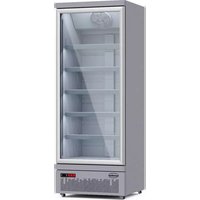
| Product type | Professional gas fryer |
| Brand | CombiSteel |
| Model | 7455.0976 |
| Dimensions (W x D x H) | 393 x 750 x 1160 mm |
| Power supply | Gas (G20/G25, G30/G31 depending on version) |
| Nominal power | 27 kW (for model GF3) |
| Temperature range | 120°C to 195°C (7 positions) |
| Capacity | 2 frying baskets included |
| Material | Stainless steel |
| Compatible gas type | I2H, I2E, I2E+, I3+ (depending on country) |
| Safety | Flame failure detector, emergency thermal switch |
| Included accessories | 2 baskets, grid, oil drain hose, clogging cap |
| Minimum installation distances | Lateral: 150 mm, rear: 50 mm |
| Gas connection | Female BSP 1/2" |
| Maintenance | Regular cleaning with mild detergent, avoid metal sponges |
| Warranty | Subject to conditions of local distributor, correct installation and use required |
| Service | Annual check recommended by an authorized person |
Frequently Asked Questions - 7455.0976 CombiSteel
User questions about 7455.0976 CombiSteel
0 question about this device. Answer the ones you know or ask your own.
Ask a new question about this device
Download the instructions for your Deep fryer in PDF format for free! Find your manual 7455.0976 - CombiSteel and take your electronic device back in hand. On this page are published all the documents necessary for the use of your device. 7455.0976 by CombiSteel.
USER MANUAL 7455.0976 CombiSteel
CombiSteel catering equipment
Fryer 7455.0976 - 7455.0999
User Manual Gebruikershandleiding Gebrauchsanweisung Le mode d'emploi
natural_image
Front view of a white industrial gas washing machine with two side washers and control panel (no visible text or symbols)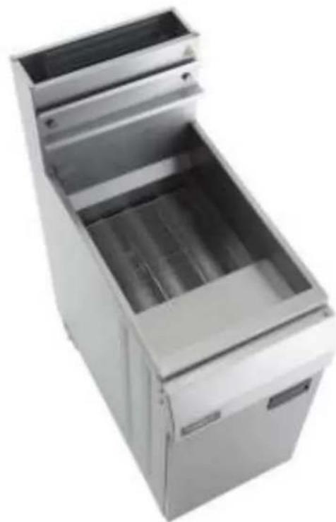
natural_image
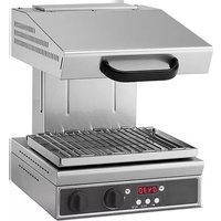
Exterior view of a stainless steel kitchen appliance with open lid (no text or symbols visible)CONTENT
ENGLISH
- WARNINGS....5
- INTRODUCTION....6
2.1 GENERAL 6
2.2 WARRANTY 6
- GENERAL INFORMATION 6
3.1 INSPECTION 6
3.2 OPERATOR MANUAL 7
3.3 INSTALLATION 7
3.4 GAS CONNECTION....7
3.5 GAS PRESSURE 7
3.6 COMMISSIONING....7
- SPECIFICATIONS 7
4.1 INSTALLATION 7
4.2 APPLIANCE SPECIFICATION 8
4.3 TEST POINT PRESSURE 9
4.4 VENTILATION AND AIR SUPPLY 9
4.5 DIMENSIONS....9
4.6 ACCESSORIES....9
- OPERATING INSTRUCTIONS .... 10
5.1 LIGHTING INSTRUCTIONS 10
5.2 IGNITION PROCEDURE 10
6.1 CLEANING STAINLESS STEEL 12
- SERVICE....13
7.1 RECOMMENDED SERVICE 13
7.2 BURNER ADJUSTMENTS....13
7.3 SPARE PARTS 14
- TROUBLE SHOOTING....14
- EXPLODED VIEW OF GF4/GF4L 15
9.1 BILL OF MATERIAL (GF4/GF4L) 16 - EXPLODED VIEW OF GF3/GF3L (7455.0999, 7455.0976)....17
10.1 BILL OF MATERIAL GF3/GF3L (7455.0999, 7455.0976)....18
NEDERLANDS
- WAARSCHUWINGEN 19
-
INTRODUCTIE 20
-
ALGEMENE INFORMATIE....20
3.1 INSPECTIE....20
3.2 HANDLEIDING GEBRUIKER 21
3.3 INSTALLATIE....21
3.4 GASAANSLUITING 21
3.5 GASDRUK 21
3.6 INBEDRIJFSTELLING....21
- SPECIFICATIONS....21
4.1 INSTALLATIE....21
4.2 AANSLUITSPECIFICATIE 22
4.3 DRUKTESTPUNT 23
4.4 VENTILATIE EN LUCHTTOEVOER....23
4.5 AFMETINGEN 23
4.6 ACCESSOIRES....23
text_image
Warning symbol with exclamation mark inside a triangle on a yellow backgroundIMPROPER INSTALLATION, ADJUSTMENT, ALTERATION, SERVICE OR MAINTENANCE CAN CAUSE INJURY OR DEATH. THE INSTRUCTION MANUAL MUST BE READ CAREFULLY BEFORE INSTALLING, OPERATING OR SERVICING THIS EQUIPMENT

text_image
Warning symbol with exclamation mark inside a triangle on a yellow backgroundTO BE INSTALLED ONLY BY AN AUTHORISED PERSON IN ACCORDANCE WITH LOCAL AUTHORITY, GAS, ELECTRICITY, AND ANY APPLICABLE STATUTORY REGULATIONS AND MANUFACTURER REQUIREMENTS.

text_image
Warning symbol with exclamation mark inside a triangle on a yellow backgroundTHIS EQUIPMENT IS DESIGNED FOR COMMERCIAL CATERING PURPOSES AND WILL GENERATE SIGNIFICANT HEAT. IT CAN ONLY BE USED BY A QUALIFIED PEOPLE. HOT SURFACES WILL CAUSE BURNS. A HAZARD AND RISK ASSESSMENT MUST BE UNDERTAKEN BY OWNERS AND ALL OPERATORS MUST BE AWARE OF THESE.

text_image
Warning sign with exclamation mark inside a triangle on yellow backgroundDO NOT STORE OR USE FLAMMABLE LIQUIDS NEAR THIS APPLIANCE. TH PARTS WHICH HAVE BEEN PROTECTED BY THE MANUFACTURER OR HIS AGENT SHALL NOT BE ADJUSTED BY THE USER.

text_image
Warning symbol with exclamation mark inside a triangle, commonly used to indicate caution or hazard.DO NOT SPRAY AEROSOLS NEAR THIS APPLIANCE WHILE IT IS IN OPERATION.

text_image
Warning symbol with exclamation mark inside a triangle on a yellow backgroundINSTALLATION CLEARANCES AS SPECIFIED MUST BE OBSERVED.

text_image
Warning sign with exclamation mark inside a triangle, set against a yellow backgroundIF YOU SMELL GAS, TURN THE UNIT AND THE MAIN GAS SUPPLY VALVE TO THE UNIT OFF. CONTACT YOUR GAS SUPPLIER OR AN AUTHORISED PERSON.

text_image
Warning sign with exclamation mark inside triangle, commonly used to indicate hazardous or hazardous itemsBEFORE TURNING ON THE MAIN GAS SUPPLY, CHECK THE UNIT TO BE CERTAIN THAT ALL THE VALVES ARE IN THE "OFF" POSITION.
PLEASE KEEP THIS MANUAL FOR FUTURE REFERENCE AND REFERENCE BY ALL OPERATORS.
2. INTRODUCTION
2.1 GENERAL
The gas fuelled fryer is designed for commercial catering purposes and incorporates a wide range of features to benefit the customer.
2.2 WARRANTY
This product's warranty is subject to the terms of a local distributor in your own country and is subject to the correct installation, operation, maintenance and care of the equipment.
Warranty does not extend to:
• Damages caused during shipping
• Damage as a result of incorrect installation.
• Damage as a result of incorrect operation
• Damages caused by unauthorised service and use of non-original parts
• Gas supply issues to the equipment
- Failure resulting from improper maintenance.
- Failure as a result of tampering with, removal of, or changing any pre-set control or safety device
For all warranty work, authorized service and genuine and authorized spare parts, please contact your local dealer
Please ensure you quote the Model and Serial Number of the unit. The Model and Serial Number of the unit are on the data plate. Please provide this information for after sales service.
3. GENERAL INFORMATION
3.1 INSPECTION
Please inspect the unit on receipt. If the unit is damaged, contact the carrier immediately and file a damage claim with them. Save all packing materials when filing a claim. Freight damage claims are the responsibility of the purchaser and are not covered under warranty.
3.2 OPERATOR MANUAL
This manual contains important information for your safety and the installation, operation, maintenance and service of this equipment. Please read the manual carefully and ensure all operators of the equipment are aware of the contents and safety requirements.
Warning: You must assess all hazards and risks associated with the operation of the equipment in your environment and advise all operators of them.
3.3 INSTALLATION
This equipment must be installed by an authorized person in accordance with local authority, gas, electricity, and any applicable statutory regulations and manufacturer requirements.
3.4 GAS CONNECTION
The appliance must be connected by an authorized person to the gas type specified on the unit. The gas type is shown adjacent to the gas connection point on the rear panel and on the data plate. Connect to and use only the correct type of gas.
3.5 GAS PRESSURE
The authorized person installing this equipment must ensure that the gas operating pressure is the same as shown on the data plate and that there is sufficient gas volume.
3.6 COMMISSIONING
The authorized person installing this equipment must commission the equipment in accordance with local gas safety regulations - gas leakage, operational checking, adjustments and instructing the owner on use of the equipment are prescribed requirements.
4. SPECIFICATIONS
4.1 INSTALLATION

THIS EQUIPMENT MUST BE INSTALLED BY AN AUTHORIZED PERSON IN ACCORDANCE WITH LOCAL AUTHORITY, GAS, ELECTRICITY, ANY APPLICABLE STATUTORY REGULATIONS AND MANUFACTURER REQUIREMENTS.
NOTE: INSTALLATION IS THE RESPONSIBILITY OF THE OWNER
Gas Inlet Connection: 1/2" BSP Female.
Gas Connection Point: The gas connection point is located at the rear of the unit. Details are shown in the drawings at the rear of this manual.
Gas Connection: The appliance must be connected by an authorized person to the gas type specified on the unit. The gas type is shown adjacent to the gas connection point on the rear panel and on the data plate. Connect to and use only the correct type of gas.
The authorized person installing this equipment must comply with local gas safety standard. Prescribed requirements include, commission the equipment, gas leakage testing, operational checking and adjustments.
All units are tested and adjusted at the factory; however, all burners and pilots must be checked at the installed location and adjusted as necessary.
Data Plate: The data plate is located at the rear of the fryer
Installation Clearances: The MINIMUM clearance from combustible surfaces is;
Sides 150 mm, and
Rear 50mm
Adequate clearance must also be provided for service.
Levelling: To adjust the legs to level the unit to the floor and/or to slightly adjust the height of the unit, raise the front of the unit and adjust the legs (ensure safe work practices).
Similarly, raise the back of the unit and adjust the legs. DO NOT LAY THE UNIT ON ITS
| Product name | Gas Fryer | Type of appliances | Type A1 | |
| Gas Category | I2H | I2E | I2E+ | I_2(43.46-45.3 MJ/m3 (0°C)) |
| Gas and Supply Pressure | G20 at 20 mbar | G20 at 20 mbar | G20/G25 at 20/25 mbar | G25.3 at 25 mbar |
| Country of Des na on | AT, BG, CR, CZ, DK, EE, FI, GR, HR, HU, IS, IE, IT, LV, LT, NO, PT, RO, SK, SI, ES, SE, CH, TR and GB | BE, FR | DE, LU, PL | NL |
| Injector Size | ∅ 2.30 mm | ∅ 2.24 mm | ||
| Gas Consump on | 34kW(3.6m3/h) for GF4;27KW(2.9m3/h) for GF3 | 32kW(3.4m3/h) for GF424kW(2.5m3/h) for GF3 | ||
| Product name | Gas Fryer | Type of appliances | ||
| Appliance category | I3+(28-30/37) | I3B/P(30) | I3B/P(50) | |
| Gas and Supply Pressure | G30 Butane at 28-30 mbar and G31Propane at 37mbar | G30 Butane and G31Propane at 30mbar | G30 Butane and G31Propane at 50mbar | |
| Country of Des na on | BE,CH,CY,CZ,ES,FR,GB,GR,IE,IT,LT,LU,LV,PT,SK,SI | BE,CY,DK,EE,FI,FR,HU,IT,LT,NL,NO,SE,SI,SK,RO,HR,TR,BG,IS,LU,MT | AT,CH,DE,SK | |
| Injector Size | ∅ 1.5 mm | ∅ 1.3 mm | ||
| Gas Consump on | 34kW (2681g/h) for GF4L; 27kW (2129g/h) for GF3L | |||
Warning: This appliance shall be installed in conformity with the current regulations and used only in a well-ventilated location. Consult the instructions before installing and using this appliance.
Burner rating of ignition pilot: 750W
Nominal Gas Consumption Table for I2H only (reference only)
| BURNER | Test pressure at gas inlet | Test pressure at test point |
| GF4 | 20 mbar | 13.5 mbar |
| GF3 | 20 mbar | 14.7 mbar |
| BURNER | Test pressure at gas inlet | Test pressure at test point |
| GF4 / GF3 | 25 mbar | 20 mbar |
| BURNER | Test pressure at gas inlet | Test pressure at test point |
| GF4L | 29 mbar | 28.0mbar |
| GF3L | 29mbar | 28.4mbar |
| GF4L | 50 mbar | 48.5mbar |
| GF3L | 50mbar | 49.5mbar |
Note: The pressure test point is located on the gas manifold (refer below).
4.3 TEST POINT PRESSURE
The pressure test point is located on the gas manifold and is accessed by opening the door. The test point pressure is shown in the 'Nominal Gas Consumption Table' above and is set with the burners operating at maximum setting.
4.4 VENTILATION AND AIR SUPPLY
All gas burners and pilots require sufficient air to operate. For optimum performance and for your safety, it is ESSENTIAL that the equipment, in the installed position, has the proper air and ventilation and the correct exhaust/canopy and air balance. The correct installation and compliance with all regulatory and other requirements is the responsibility of the purchaser/owner.
Please note that a strong exhaust canopy will create a vacuum if there is insufficient replacement air. The amount of air exhausted must be replaced by an equal amount of air. Airflow to the appliance must not be blocked or restricted (e.g. large objects should not be placed in front of the appliance). The flue must never be covered or restricted in any way.
4.5 DIMENSIONS
* Please note that the outside dimensions of GF3/GF4 and GF3L/GF4L are identical.
* Product dimensions are 393 x 750x 1160 mm
* Packing dimensions are 510 x 820 x 1230 mm
4.6 ACCESSORIES
- Fry baskets @ 2
- Rack @ 1
- Oil extension pipe @ 1
- Clog clearance prod @ 1
- Operating manual @ 1
5. OPERATING INSTRUCTIONS
5.1 LIGHTING INSTRUCTIONS

DO NOT OPERATE THE UNIT UNLESS IT HAS BEEN INSTALLED AND COMMISSIONED BY AN AUTHORIZED PERSON.

BEFORE TURNING ON THE MAIN GAS SUPPLY, CHECK AND ENSURE THAT ALL THE VALVES ARE IN THE "OFF" POSITION.

THIS EQUIPMENT IS DESIGNED FOR COMMERCIAL CATERING PURPOSES AND WILL GENERATE SIGNIFICANT HEAT. HOT SURFACES WILL CAUSE BURNS. A HAZARD AND RISK ASSESSMENT MUST BE UNDERTAKEN BY OWNERS AND ALL OPERATORS MADE AWARE OF THESE.
NOTE: Ensure the gas supply to the equipment is turned ON.
NOTE: For your safety, the valve comes with a flame failure sensing device. If the device does not sense a flame, gas supply to the burner will be cut.
5.2 IGNITION PROCEDURE

natural_image
Top-down view of a beige industrial control panel with a rotary dial and two black buttons (no visible text or symbols)NOTE: Ensure the gas supply to the equipment is turned ON
1) Starting from the "0" position
2) Press the PILOT ★ position.
3) Manually light the pilot by use of a spark gun or lighter.
4) Continually press the ★ button for 15 seconds. Now when the ★ button is released, the pilot flame should stay alight. If it does not, go back to step (1) and start all over again. When the automatic valve senses that the pilot is alight, the gas flow to the main burner is opened.
5) If the pilot flame cannot be lit after repeated attempts, check out the troubleshooting page of this manual.
6) Turn the knob to setting "1".
7) Turn the knob to the setting of your desired temperature. Please refer to the following table.
| Setting | 1 | 2 | 3 | 4 | 5 | 6 | 7 |
| °C | 120 | 135 | 145 | 160 | 175 | 185 | 195 |
| °F | 248 | 275 | 293 | 320 | 347 | 365 | 383 |
When the oil temperature reaches the desired temperature (normally at this point of time, the main burner will be temporarily closed), the fryer can be loaded.
Warning:
• Operator must follow the procedure in operating this fryer
• Take particular care when loading the food into the fryer to avoid being scalded by splashing oil.
- Hang the fry basket on the hangar until oil is dripped out.
- Do not overload the fryer basket.
Pilot Standby Position
To turn the main burner off and keep the pilot ON, rotate the knob to "0" position.
Shut Down/Pilot OFF
• Turn the control knob to "0" position
- Depress the ● knob. Gas supply to both the main burner as well as the pilot burner will be cut off simultaneously.
NOTE: If the pilot flame were accidentally extinguished, the flame failure safety device would operate and cut the gas flow to the main burner. It would then be necessary to re light the pilot by following the above procedure.
• Wait for about 15 seconds for the valve to reset.
• Repeat from step (1) of the IGNITION PROCEDURE
Thermal cut out tripping:
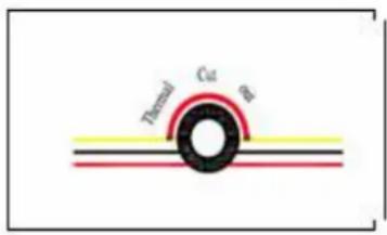
text_image
Thermal Cu BWait for about 10 minutes for the oil to cool down
Press the button on the thermal cut out. If the thermal cut out cannot be manually reset, call your service agent.
Repeat step (1) from IGNITION PROCEDURE to light up the fryer again.
Adding Oil
Caution: Add oil to fry pot between the maximum and minimum level.
Caution: Do not use solid oil or solid shortening. Only liquid oil should be used in this fryer
Oil filtering procedure:
1) Turn off the fryer and let it cool down for about 20 minutes
2) Screw in the Oil drain extension pipe (hung on the inside of the door) to the drain valve outlet
3) Make sure that the nozzle end of the oil drain extension pipe faces an oil collector (or an oil filtering cart) Pull the safety latch of the lever and start turning the lever anticlockwise slowly.
CAUTION: DO NOT TURN THE LEVER TOO FAST. THIS COULD RESULT IN HOT OIL SPLASHING OUT FROM THE DRAIN NOZZLE
Oil filtering
Oil should be filtered regularly in order to lengthen its usable life span. This will also reduce the operating cost.
The following factors all contribute to the shortening of oil life.
← Contact with air
← Carbonated food crumbs and particles.
Contact with any surface other than stainless steel.
← Contact with seasoning, spices and salt.
Cooking food under a temperature too high
Warning: Ensure the appliance is off and the parts are cool to touch.
- Avoid splashing water onto any parts and piping.
- Check the piping connections and gas circuitry regularly.
- Avoid clogging of the flue gas ventilation. Any obstacles in the flue can cause incomplete combustion.
- Make sure the gas type and pressure conforms to the specification as shown in the data plate
Cleaning must be regular and thorough to ensure safe and efficient operation of the equipment and to prevent flare-up. The amount of usage and the type of products being cooked will largely determine how often complete cleaning is necessary - you must assess this.
To clean the items, use a suitable detergent and warm water and scrubbing brush. Repeated scrubbing will be necessary if deposits are heavy and baked on.
6.1 CLEANING STAINLESS STEEL
Regularly wipe the surface with hot water and detergent. Rinse the washed area with a wet sponge and clean water and wipe the area dry to prevent streaking. Follow this process and wash a small area at a time to prevent chemical residue and streaking.
Stainless steel may discolour if overheated. These stains can usually be removed using an appropriate powder/paste. To scrape off heavy deposits of grease and oil, use only wood or plastic tools as necessary.
Note: Never use steel wool to clean stainless steel.
Note: Damage may occur if chemicals not suitable for stainless steel are used.
7. SERVICE

FOR YOUR SAFETY, ALL SERVICE WORK MUST BE CARRIED OUT BY AN AUTHORISED PERSON AND USE ONLY ORIGINAL SUPPLIED AND SPECIFIED PARTS.

TEST ALL FITTINGS, PIPES AND PIPE CONNECTIONS FOR LEAKS IN ACCORDANCE WITH APPROVED GAS LEAK TEST PROCESSES AND METHODS. DO NOT USE A FLAME
7.1 RECOMMENDED SERVICE
It is recommended that your appliance be serviced by an authorized person every 12 months. This period is for guidance purpose only and may vary based on usage of the equipment and operator care. Prescribed service tasks include;
• Functional test of all components and clean and adjust as necessary.
• Inspect and clean all gas valves and lubricate with an industry approved lubricant.
- Inspect all gas piping.
- Check and adjust specified gas pressures.
- Leak test.
• Full operational, performance and safety test.
7.2 BURNER ADJUSTMENTS
Leak Test
1) Ensure that all control valves are in the OFF position.
2) Turn on the main gas supply valve.
3) Light all pilots.
4) Leak test all valves and fittings using approved methods.
5) Correct any leaks as required and re-check.
6) Shut off all valves and set the control knobs to "OFF" position.
Test Point Pressure
The pressure test point is located on the gas manifold. The gas manifold and pressure test point is accessed by opening the fryer door. The test point pressure is shown in the 'Nominal Gas Consumption Table' and is set with the burners operating at maximum setting.
Pilot Burner Adjustment
Set all pilots so that the flame envelops the tip of the thermocouple by adjusting the pilot flame adjusting screw on the gas valve - clockwise to decrease, or counter clockwise to increase.
Service adjustment should not be necessary unless you're changing the gas valve or performing a gas conversion.
Burner Adjustment
The burner orifices are fixed as specified and cannot be adjusted. The specified gas rate will be achieved if the gas supply pressure and test point pressure is correct.
A distinct blue flame over the entire port area of the burner will be achieved at full rate when the air supply is correct and the injector and burner are properly aligned.
If the flame is yellow and wavy, the cause needs to be established.
WARNING: If you are not competent in performing any service task or require assistance, please contact your local service agent.
7.3 SPARE PARTS
A list of major spare part items is shown at the end of this manual.
These parts and all other parts used in the fryer are available at your local dealer.
Warning: Use only genuine spare parts.
Warning: Use of non-authorized parts voids warranty and equipment approval.
8. TROUBLE SHOOTING

ALL SERVICE WORK TO BE COMPLETED BY AN AUTHORISED PERSON.
BURNERS
| Condition | check |
| Pilot will not light. | Gas supply is on and gas pressure is correct |
| Blocked pilots | |
| Pilot adjusting screw | |
| Pilot repeatedly goes out. | Pilot flame size and position |
| Thermocouple | |
| Flame safety device | |
| Yellow Burner Flame. | Primary air |
| Flame lifting off burner ports. | Primary air |
| ‘Popping’ after turning off. | Primary air |
| Burner flame too large. | Gas pressure |
| Delayed ignition. | Pilot flame |
| Burner and ports clean | |
| Gas pressure | |
| Flame burns back to orifice | Primary air |
9. EXPLODED VIEW OF GF4/GF4L
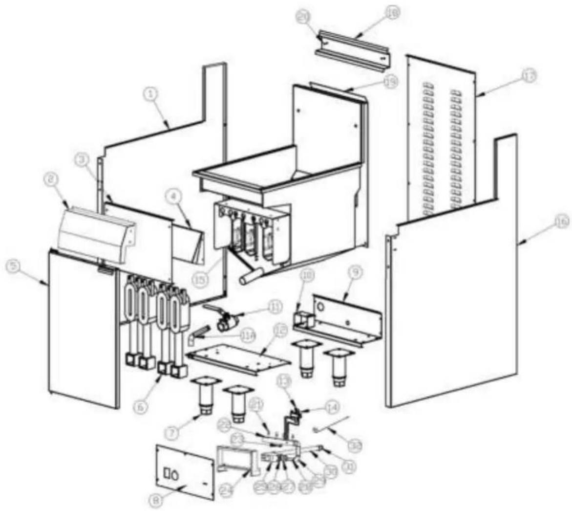
text_image
Exploded diagram of a server rack system with numbered components for identification9.1 BILL OF MATERIAL (GF4/GF4L)
| Item | Description | P/N | Drawing # | Qty |
| 1 | Left panel | 10113062 | 1 | |
| 2 | Front panel | S15015 | B-GF-GY02 | 1 |
| 3 | Shield | 10113055 | 1 | |
| 4 | Front baffle | 10113044 | 1 | |
| 5 | Door | S01097 | B-GF-MZJ-01 | 1 |
| 6 | Burner | B06181 | B-GF-JS-01-11 | 4 |
| 7 | Feet | S99002 | 2 | |
| 8 | Control panel | 10113060 | 1 | |
| 9 | Rear bottom | 10113054 | 1 | |
| 10 | Gas pipe bracket | 10113039 | 1 | |
| 10A | Internal Baffle | B-JS-GF-01 | 4 | |
| 11 | Drain valve | B09022 | 1 | |
| 11A | Drain pipe | S15029 | 1 | |
| 12 | Front bottom | 10113007 | 1 | |
| 13 | Pilot | B06362 | 1 | |
| 14 | Thermocouple | SIT-0.200.015 | 1 | |
| 15 | Caster | B05080 | 2 | |
| 16 | Right panel | 10113053 | 1 | |
| 17 | Back | 10113014 | 1 | |
| 18 | Basket hangar | 10113029 | 1 | |
| 19 | Frypot Ass'y | S15013 | B-GF4-GYGF4 | 1 |
| 20 | Screw | S15012 | 2 | |
| 21 | Injector | S15002 | 4 | |
| 22 | Manifold Ass'y | B-GF4C-LJ03 | 1 | |
| 23 | Pressure test point | B06383 | 1 | |
| 24 | Manifold support | 10113059 | 1 | |
| 25 | Gas valve | B06330 | 1 | |
| 26 | Reducer | B11089 | 1 | |
| 27 | Coupler | B14017 | 2 | |
| 28 | Gas pipe | B-GF4C-LJ01 | 1 | |
| 29 | Elbow | B12008 | 2 | |
| 30 | Gas inlet pipe | B-GF4-LJ01 | 1 | |
| 31 | Reducer | B11014 | 1 | |
| 32 | Hi limit | E03040 | 1 |
- EXPLODED VIEW OF GF3/GF3L (7455.0999, 7455.0976)
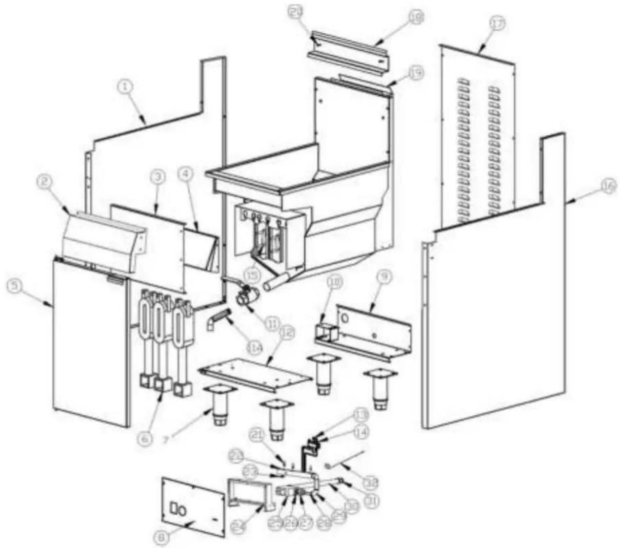
text_image
Technical diagram of an industrial machine with numbered components for identification and assembly reference.10.1 BILL OF MATERIAL GF3/GF3L (7455.0999, 7455.0976)
| Item | Description | P/N | Drawing # | Qty |
| 1 | Left panel | 10113062 | 1 | |
| 2 | Front panel | S15015 | B-GF-GY02 | 1 |
| 3 | Shield | 10113055 | 1 | |
| 4 | Front baffle | 10115013 | 1 | |
| 5 | Door | S01097 | B-GF-MZJ-01 | 1 |
| 6 | Burner | B06181 | B-GF-JS-01-11 | 3 |
| 7 | Feet | S99002 | 2 | |
| 8 | Control panel | E13155 | 1 | |
| 9 | Rear bottom | 10113054 | 1 | |
| 10 | Gas pipe bracket | 10113039 | 1 | |
| 10A | Internal Baffle | B-JS-GF-01 | 3 | |
| 11 | Drain valve | B09022 | 1 | |
| 11A | Drain pipe | S15029 | 1 | |
| 12 | Front bottom | 10113007 | 1 | |
| 13 | Pilot | B06362 | 1 | |
| 14 | Thermocouple | SIT-0.200.015 | 1 | |
| 15 | Caster | B05080 | 2 | |
| 16 | Right panel | 10113053 | 1 | |
| 17 | Back | 10113014 | 1 | |
| 18 | Basket hangar | 10113029 | 1 | |
| 19 | Frypot Ass'y | S15016 | B-GF3-RGGY | 1 |
| 20 | Screw | S15012 | 2 | |
| 21 | Injector | S15002 | 3 | |
| 22 | Manifold Ass'y | B-GF4C-LJ03 | 1 | |
| 23 | Pressure test point | B06383 | 1 | |
| 24 | Manifold support | 10113059 | 1 | |
| 25 | Gas valve | B06330 | 1 | |
| 26 | Reducer | B11089 | 1 | |
| 27 | Coupler | B14017 | 2 | |
| 28 | Gas pipe | B-GF4C-LJ01 | 1 | |
| 29 | Elbow | B12008 | 2 | |
| 30 | Gas inlet pipe | B-GF4-LJ01 | 1 | |
| 31 | Reducer | B11014 | 1 | |
| 32 | Hi limit | E03040 | 1 |
1. WAARSCHUWINGEN

text_image
Warning symbol with exclamation mark inside a triangle on a yellow backgroundONJUISTE INSTALLATIE, AANPASSING, WIJZIGING, SERVICE OF ONDERHOUD KAN LEIDEN TOT LETSEL OF DOOD. DE HANDLEIDING MOET ZORGVULDIG WORDEN GELEZEN VOORAFGAAND AAN HET INSTALLEREN, BEHEREN OF ONDERHOUD VAN DEZE APPARATUUR

text_image
Warning symbol with exclamation mark inside a triangle on a yellow backgroundMAG ALLEEN WORDEN GEINSTALLEERD DOOR EEN BEVOEGD PERSOON OVEREENKOMSTIG DE VOORSCHRIFTEN VAN DE LOKALE AUTORITEITEN, ALLE TOEPASSELIJKE WETTELIJKE VOORSCHRIFTEN T.A.V. GAS EN ELEKTRICITEIT, EN DE VEREISTEN VAN DE FABRIKANT

text_image
Warning symbol with exclamation mark inside a triangle on a yellow backgroundDIT APPARAAT IS ONTWORPEN VOOR COMMERCIËLE CATERINGDOELEINDEN EN ZAL AANZIENLIJKE WARMTE GENEREREN. HET APPARAAT MOET WORDEN GEBRUIKT DOOR GEKWALIFICEERDE PERSONEN. HETE OPPERVLAKKEN KUNNEN BRANDWONDEN VEROORZAKEN. DE EIGENAREN MOETEN EEN GEVAREN- EN RISICO-ANALYSE UITVOEREN EN DEZE ONDER DE AANDACHT VAN ALLE GEBRUIKERS BRENGEN.

text_image
Warning sign with exclamation mark inside a triangle on a yellow backgroundBEWAAR OF GEBRUIK GEEN BRANDBARE VLOEISTOFFEN IN DE BUURT VAN DIT APPARAAT. DE DELEN DIE DOOR DE FABRIKANT OF ZIJN GEMACHTIGDE ZIJN BEVEILIGD MOGEN NIET WORDEN AANGEPAST DOOR DE GEBRUIKER.

text_image
Warning symbol with exclamation mark inside a triangle, commonly used to indicate caution or hazard.SPUIT GEEN AËROSOLS IN DE BUURT VAN DIT APPARAAT WANNEER DIT IN GEBRUIK IS.

text_image
Warning symbol with exclamation mark inside a triangle on a yellow backgroundDE AANGEGEVEN INSTALLATIETOLERANTIEWAARDEN MOETEN WORDEN NAGELEEFD.

text_image
Warning sign with exclamation mark inside a triangle, set against a yellow backgroundSCHAKEL ALS U GAS RUIKT HET APPARAAT DE HOOFDGASTOEVOERKLEP OP HET APPARAAT UIT. NEEM CONTACT OP MET UW GASLEVERANCIER OF EEN BEVOEGD PERSOON.

text_image
Warning sign with exclamation mark inside triangle, commonly used to indicate hazardous or hazardous itemsCONTROLEER HET APPARAAT, VOORDAT U DE HOOFDGASTOEVOER AANZET, OM ER ZEKER VAN TE ZIJN DAT DE KLEPPEN IN DE "OFF" ("UIT")-STAND ZIJN.
HOUD DEZE HANDLEIDING BIJ DE HAND VOOR CONSULTATIE IN DE TOEKOMST EN TER REFERENTIE VOOR ALLE GEBRUIKERS.
2. INTRODUCTIE
2.1 ALGEMEEN
natural_image
Close-up of a beige control panel with a rotary dial and two black buttons featuring red star patterns (no text or symbols visible)1) Ensure that all control valves are in the OFF position.
2) Turn on the main gas supply valve.
3) Light all pilots.
4) Leak test all valves and fittings using approved methods.
5) Correct any leaks as required and re-check.
6) Shut off all valves and set the control knobs to "OFF" position.
Drukmeetpunt
text_image
Technical diagram of a device with numbered components, likely illustrating internal components and assembly relationships.9.1 MATERIAALLIJST (GF4/GF4L)
text_image
Technical diagram of a multi-level electronic device with numbered components for identification.10.1 MATERIAALLIJST GF3/GF3L (7455.0999, 7455.0976)
| Item | Description | P/N | Drawing # | Qty |
| 1 | Linker paneel | 10113062 | 1 | |
| 2 | Voorpaneel | S15015 | B-GF-GY02 | 1 |
| 3 | Schild | 10113055 | 1 | |
| 4 | Asorptieplaat vóór | 10115013 | 1 | |
| 5 | Deur | S01097 | B-GF-MZJ-01 | 1 |
| 6 | Brander | B06181 | B-GF-JS-01-11 | 3 |
| 7 | Poten | S99002 | 2 | |
| 8 | Bedieningspaneel | E13155 | 1 | |
| 9 | Onderkant achterzijde | 10113054 | 1 | |
| 10 | Gasbuisbeugel | 10113039 | 1 | |
| 10A | Interne apsorptieplaat | B-JS-GF-01 | 3 | |
| 11 | Afvoerklep | B09022 | 1 | |
| 11A | Afvoerbuis | S15029 | 1 | |
| 12 | Voorzijde onderkant | 10113007 | 1 | |
| 13 | Waakvlam | B06362 | 1 | |
| 14 | Thermokoppel | SIT-0.200.015 | 1 | |
| 15 | Casterwieltje | B05080 | 2 | |
| 16 | Rechter paneel | 10113053 | 1 | |
| 17 | Achterkant | 10113014 | 1 | |
| 18 | Mandhanger | 10113029 | 1 | |
| 19 | Friteuse assemblage | S15016 | B-GF3-RGGY | 1 |
| 20 | Schroef | S15012 | 2 | |
| 21 | Injector | S15002 | 3 | |
| 22 | Spruitstuk assemblage | B-GF4C-LJ03 | 1 | |
| 23 | Drukmeetpunt | B06383 | 1 | |
| 24 | Spruitstuksteun | 10113059 | 1 | |
| 25 | Gasklep | B06330 | 1 | |
| 26 | Reducer | B11089 | 1 | |
| 27 | Koppel | B14017 | 2 | |
| 28 | Gasleiding | B-GF4C-LJ01 | 1 | |
| 29 | Elleboogstuk | B12008 | 2 | |
| 30 | Gasinlaatbuis | B-GF4-LJ01 | 1 | |
| 31 | Reducer | B11014 | 1 | |
| 32 | Hoge limiet | E03040 | 1 |
1. WARNHINWEISE

text_image
Warning symbol with exclamation mark inside a triangle on a yellow backgroundtext_image
Warning symbol with exclamation mark inside a triangle on a yellow backgroundtext_image
Warning symbol with exclamation mark inside triangle, commonly used to indicate hazardous or hazardous itemstext_image
Warning sign with exclamation mark inside a triangle on yellow backgroundtext_image
Warning symbol with exclamation mark inside a triangle on a yellow backgroundVERSPRÜHEN SIE KEINE AEROSOLE IN DER NÄHE DES GERÄTES WÄHREND ES IN BETRIEB IST.

text_image
Warning symbol with exclamation mark inside a triangle on a yellow backgroundtext_image
Warning sign with exclamation mark inside a triangle, set against a yellow backgroundtext_image
Warning sign with exclamation mark inside a triangle on yellow backgroundBEVOR SIE DIE HAUPTGASZUFUHR AUFDREHEN, ÜBERPRÜFEN SIE DAS GERÄT, DAMIT SICH SICHERGEHEN, DASS SICH ALLE VENTILE IN DER „AUS“-POSITION BEFINDEN.
natural_image
Close-up of a beige control panel with a rotary dial and two black buttons featuring red star patterns (no text or symbols visible)text_image
Technical diagram of a device with numbered components, likely illustrating internal components and assembly relationships.9.1 TEILELISTE (GF4/GF4L)
text_image
Technical diagram of a multi-level electronic device with numbered components for identification.10.1 TEILELISTE GF3/GF3L (7455.0999, 7455.0976)
text_image
Warning symbol with exclamation mark inside a triangle on a yellow backgroundUNE INSTALLATION, UNE ADAPTATION, UNE MODIFICATION, UNE UTILISATION OU UN ENTRETIEN INCORRECTS PEUVENT PROVOQUER DES LESIONS OU LA MORT. LE MANUEL DOIT ETRE LU ATTENTIVEMENT AVANT DE PROCEDER A L'INSTALLATION, AU MANIEMENT OU A L'ENTRETIEN DE CET APPAREIL

text_image
Warning symbol with exclamation mark inside a triangle on a yellow backgroundPEUT UNIQUEMENT ETRE INSTALLE PAR UNE PERSONNE AGREEE CONFORMEMENT AUX PRESCRIPTIONS DES AUTORITES LOCALES, A TOUTES LES PRESCRIPTIONS LEGALES RELATIVES AU GAZ ET A L'ELECTRICITE, ET AUX EXIGENCES DU FABRICANT

text_image
Warning symbol with exclamation mark inside triangle, commonly used to indicate hazardous or hazardous itemsCET APPAREIL A ÉTÉ REALISE POUR DES BESOINS DE CATERING COMMERCIAUX ET GENERE UNE CHALEUR TRES ELEVEE . L'APPAREIL DOIT ETRE UTILISE PAR DES PERSONNES QUALIFIEES. LES SURFACES CHAUDES PEUVENT OCCASIONNER DES BRULURES. LES PROPRIETAIRES DOIVENT EFFECTUER UNE ANALYSE DES DANGERS ET DES RISQUES, ET PORTER CELLE-CI A LA CONNAISSANCE DE TOUS LES UTILISATEURS.

text_image
Warning sign with exclamation mark inside a triangle on yellow backgroundNE CONSERVEZ OU UTILISEZ AUCUN LIQUIDE INFLAMMABLE A PROXIMITE DE CET APPAREIL. LES ELEMENTS QUI SONT SECURISES PAR LE FABRICANT OU SON REPRESENTANT NE PEUVENT ETRE ADAPTES PAR L'UTILISATEUR.

text_image
Warning symbol with exclamation mark inside a triangle on a yellow backgroundNE DIFFUSEZ AUCUN AEROSOL A PROXIMITE DE CET APPAREIL LORSQUE CELUI CI EST EN COURS D'UTILISATION.

text_image
Warning symbol with exclamation mark inside a triangle on a yellow backgroundLES VALEURS DE TOLERANCE D'INSTALLATION INDIQUEES DOIVENT ETRE RESPECTEES.

text_image
Warning sign with exclamation mark inside a triangle, set against a yellow backgroundEN CAS D'ODEUR DE GAZ, REFERMEZ LA VALVE D'ALIMENTATION DE GAZ PRINCIPALE SUR L'APPAREIL. PRENEZ CONTACT AVEC VOTRE FOURNISSEUR DE GAZ OU UNE PERSONNE AUTORISEE.

text_image
Warning sign with exclamation mark inside triangle, commonly used to indicate hazardous or hazardous itemsCONTROLEZ L' APPAREIL AVANT D'OUVRIR LA VALVE D'ALIMENTATION DE GAZ PRINCIPALE, POUR VOUS ASSURER QUE TOUTES LES VALVES SONT EN POSITION "OFF".
CONSERVEZ CE MANUEL A PORTEE DE MAIN POUR CONSULTATION FUTURE ET COMME REFERENCE POUR TOUT UTILISATEUR.
2. INTRODUCTION
2.1 GENERALITES
3.4 RACCORDEMENT AU GAZ
5.1 INSTRUCTIONS D'ALLUMAGE

NE METTEZ PAS L'APPAREIL EN ROUTE S'IL N'A PAS ÉTÉ INSTALLE ET MIS EN SERVICE PAR UNE PERSONNE AGREEE A CET EFFET.

AVANT D'OUVRIR L'ALIMENTATION DE GAZ, CONTROLEZ QUE TOUT EST EN ORDRE ET VEILLEZ A CE QUE TOUTES LES VALVES SOIENT EN POSITION "OFF".

CET APPAREIL A ÉTÉ CONCU POUR A DES FINS DE CATERING COMMERCIALES E GENERE UNE CHALEUR CONSIDERABLE. LES SURFACES CHAUDES PEUVENT OCCASIONNER DES BRULURES. LES PROPRIETAIRES DOIVENT PROCEDER A UNE ANALYSE DES DANGERS ET DES RISQUES, ET PORTER CELLE-CI A L'ATTENTION DE TOUS LES UTILISATEURS.
natural_image
Close-up of a rotary dial with numbered segments and a black rectangular device with a red star emblem (no visible text or symbols)text_image
Exploded diagram of a server rack system with numbered components for identification9.1 LISTE DU MATÉRIEL (GF4/GF4L)
text_image
Technical diagram of a multi-level electronic device with numbered components for identification.10.1 LISTE DU MATÉRIEL GF3/GF3L (7455.0999, 7455.0976)