7280.0030 - Dishwasher CombiSteel - Free user manual and instructions
Find the device manual for free 7280.0030 CombiSteel in PDF.
| Product type | Professional dishwasher |
| Brand | CombiSteel |
| Model | 7280.0030 |
| Power supply | 230 V ~ 50 Hz |
| Dynamic water pressure | 200 to 500 kPa (2-5 Bar) for network versions |
| Dynamic water pressure (PRS) | 100 to 500 kPa (1-5 Bar) with atmospheric superheater |
| Inlet water temperature | 10 °C to 50 °C (max 25 °C with ES/S) |
| Recommended water hardness | 5 to 20 °f (2.8 to 11 °d) |
| Control versions | Electromechanical or electronic with LCD display |
| Main functions | Self-cleaning, cold rinse (option), energy saving (Green), automatic descaling (option) |
| Wash programs | Selectable by duration (cycle indicator) |
| Safety devices | Thermal amperometric relay, door microswitch, manual reset thermostats, pressure switch, overflow pipe |
| Daily maintenance | Cleaning filters with running water, checking detergent and rinse aid dispensers |
| Descaling | Use suitable descaling products, rinse thoroughly |
| Intended use | Washing plates, glasses and cutlery in bars, restaurants, canteens |
| Supplied accessories | Basket support, wash arm, detergent and rinse aid dispensers |
| Protection rating | IPX4 |
| Noise level | Less than 70 dB(A) |
| Estimated net weight | Approximately 60-80 kg (to be confirmed on the rating plate) |
Frequently Asked Questions - 7280.0030 CombiSteel
User questions about 7280.0030 CombiSteel
0 question about this device. Answer the ones you know or ask your own.
Ask a new question about this device
Download the instructions for your Dishwasher in PDF format for free! Find your manual 7280.0030 - CombiSteel and take your electronic device back in hand. On this page are published all the documents necessary for the use of your device. 7280.0030 by CombiSteel.
USER MANUAL 7280.0030 CombiSteel
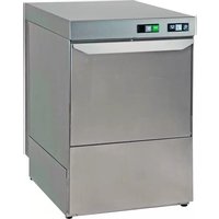
natural_image
3D rendering of a gray industrial machine with ventilation slots and control panel (no text or symbols visible)Lavabicchieri - Lavastoviglie sottobanco Undercounter Glass and Dishwashing machines Lave-verres et Lave-vaisselles à chargement frontal Untertisch Gläser und Geschirrspülmaschinen Lavavasos-Lavavajillas de carga frontal Lava-Copos/Louças sob bancada ПОСУДОМОЕЧНАЯ МАШИНА ФРОНТАЛЬНОГО ТИПА
INDICE
text_image
Technical diagram of a mechanical device with numbered components for identificationnatural_image
3D rendering of a gray industrial cabinet or enclosure unit (no visible text or symbols)natural_image
3D rendering of a gray industrial cabinet or storage unit with no visible text or symbolsnatural_image
3D illustration of a forklift lifting a brown box, no text or symbols presentnatural_image
3D illustration of a gray industrial pallet jack with a green handle and wooden pallet base (no text or symbols)INTERPORRE UN CARTONE PROTETTIVO
SCHERMATA RISCALDAMENTO RESISTENZE NELLA MACCHINA

text_image
V: 55°C B: 82°C COLORE GIALLO-
Introduction......28
-
Safety instructions: symbols and definitions.... 29
2.1 Symbols.... 29
2.2 Definitions.... 29
2.3 Machine identification.... 30
2.4 Keeping the instruction manual and EC declaration.... 30
2.5 Personal Protective Equipment (PPE).... 30
2.6 Protection devices and guards installed.... 31
2.7 Information regarding use and maintenance.... 31
- Description, characteristics and intended use.... 32
3.1 Dishwasher versions.... 32
- Installation.... 33
4.1 Storage.... 33
4.2 Machine handling.... 33
4.3 Water connection.... 34
4.4 Electrical connection.... 34
4.5 Safety devices installed.... 35
- Description of controls.... 36
5.1 Electromechanical version.... 36
5.2 Electronic version with LCD display.... 36
- Startup, first switch-on.... 37
6.1 Controls and adjustments.... 37
6.2 First switch-on.... 37
6.3 Electromechanical version.... 39
6.4 Electronic version with LCD display (first switch-on).... 39
6.5 Electronic version with LCD display.... 42
6.6 Cleaning function 43
6.7 Cold rinse function (option) 43
6.8 Energy Saving function.... 44
6.9 Programming (user) 44
6.10 Errors that can be displayed.... 45
- Automatic water softener (option).... 46
7.1 Operation.... 46
7.2 Installation 47
7.3 Maintenance.... 47
-
Daily use....50
-
Care and maintenance.... 50
-
Troubleshooting....51
1. INTRODUCTION
This instruction manual provides the user with the necessary information for the correct and safe operation, avoiding damage to people, property or animals. It is very important, therefore carefully read the information given for each stage, from transport to installation, commissioning, use, maintenance, repair and dismantling the machine, in order to prevent incorrect handling and problems that could affect the integrity of the machine or be dangerous. The manual must always be available to the operator and kept with care in the place where the machine is used, so that it
is readily at hand in case of any doubts or uncertainties. Do not hesitate to contact the installer or the technical assistance service if explanations on machine operation are necessary. During all stages of use, always respect the current regulations on safety, work hygiene and environmental protection. Therefore it is up to the user to make sure the machine is started and operated only in optimum safety conditions.

ATTENTION! DO NOT WASH THE APPLIANCE WITH DIRECT OR HIGH-PRESSURE JETS OF WATER
| Min 10 °C – Max 50 °CMin 10 °C – Max 25 °C with ES / S | |
| 200÷500 kPa (2÷5 Bar)100÷500 kPa (1÷5 Bar) with PRS Atmospheric Boiler | |
| °f °d | Water hardness 5÷20 °f – 2,8÷11 °d |
2. SAFETY INSTRUCTIONS: SYMBOLS AND DEFINITIONS
This appliance can be used by minors and adults with limited physical or sensory capabilities or limited experience and knowledge regarding its use, only if supervised or if they have been instructed in its use and if they understand the risks involved. Do not allow children to play with the appliance. Cleaning and maintenance must not be carried out without supervision.
2.1 Symbol
This manual describes situations and activities that require levels of attention and precaution indicated by the symbols listed below:

Electrical hazards
Failure to follow instructions can cause damage to people, goods and animals
Failure to follow instructions can cause damage to the dishwasher
Indications or situations which require particular attention
Throughout the text, symbols with safety warnings briefly exemplify the types of hazards. The drawings and diagrams in the manual supplement the information but are not intended to be a detailed representation of the machine supplied.
2.2 Definitions
Listed below are the definitions of the main terms used. Installer The person responsible for machine installation, adjustment, use, maintenance, cleaning, repair and transport.
User
The person who takes care of the machine operation, regular maintenance and cleaning.
Operator for normal machine use
An operator who has been informed and trained regarding the tasks and hazards involved in normal machine use.
After-sales service or specialised technician An operator instructed/trained by the Manufacturer and who, based on his professional and specific training, experience and knowledge of the safety regulations, is able to assess the operations to be carried out on the machine and recognise and prevent any risks. His competence encompasses mechanical, electrotechnical and electronics fields.
Customer
The person/party who purchased the machine and/or who manages and uses it (e.g. company, businessperson, firm).
Manufacturer
The manufacturer of the machine.
Dealer
Authorised dealer.
Danger
A source of possible injury or harm.
Hazardous situation
Any situation where a user or installer is exposed to one or more hazards.
Risk
A combination of probabilities and risks of injury or harm in a hazardous situation
Protection devices
Safety measures consisting of the use of specific technical means (shields and safety devices) for protecting operators from hazards.
Shield
An element of a machine used in a specific way to provide protection by means of a physical barrier.
Safety device
A device (other than a shield) that eliminates or reduces the risk; it can be used alone or in conjunction with a shield.
Emergency stop device
A set of components for the emergency stop function; the device is activated with
a single action and prevents or reduces damage to people/machines/property/animals.
Electrocution
An accidental discharge of electric current on a human body.
2.3 Machine identification
Identification is displayed on the CE plate affixed to the machine; the following is an example with the meaning of the data given.
| MODEL | XXXX | |||
| TYPE | XXXX | 230 V | 50 Hz | |
| CODE | XXXX-XXXX | XX | A | |
| S/N | YYYYYYYY | |||
| ARTICLE | POWER | XXXX | W | |
| MATERIALS | 300-500 MPa/MAX 50°C | IPX4 | ||
| Electronic code: | XXXX | PW, XXX | ||

To contact the manufacturer, always refer to the details given on the data plate.
MODEL: machine name
TYPE: machine type
CODE: machine code
S/N: machine serial number
230V \~ 50 Hz power supply
absorbed current
Power: total installed power
IPX4: insulation rating
Electronic code: PCB code
PW: password to access menu parameters

Do not remove the data plate or make it illegible.
Do not remove the data plate's transparent protection.
2.4 Keep the instruction manual and EC certificate in a safe place
The documentation supplied with the machine must be kept for its entire life and remain with the machine in case of sale, lease or other financial transactions.
In particular, the instruction manual must be made available to machine transport, handling, installation and operation personnel, as well as the employer and specialised service technicians.
2.5 Personal Protective Equipment (PPE)
The following table lists the main personal protective equipment to be used during the various stages of the machine's life cycle.
| FASE | PRODUCTION OF 2015/2016 | SAVILITY OF 2015/2016 | NO. (2015) | ||
| Transport | — | ● | ○ | — | ○ |
| Handling | ● | ● | ○ | — | — |
| Unpacking | ○ | ● | ○ | — | — |
| Installation | ○ | ● | ○ | — | — |
| Normal use | ● | ● | ●* | ○ | — |
| Adjustments | ○ | ● | — | — | — |
| Routine cleaning | ○ | ● | ●* | ○ | — |
| Extraordinary cleaning | ○ | ● | ●* | ○ | — |
| Maintenance | ○ | ● | ○ | — | — |
| Diamantling | ○ | ● | ○ | — | — |
| Scrapping | ○ | ● | ○ | — | — |
Legend
| ● | PPE Required |
| ○ | PPE available or to be used if necessary |
| — | PPE Not Required |
* Gloves must be used for exposure to high temperatures and suitable for contact with corrosive substances.

Failure to use PPE exposes operators to health risks.
2.6 Protection devices and shields installed
The machine has fixed protection devices (side panels, casings, covers, etc.) rigidly secured and removable or openable only with utensils or tools. The doors (fixed or hinged) which access the electrical fittings, can only be opened with utensils or tools.

The machine must not be handled with fixed shields removed due to possible components under pressure, hot or exposing live parts.

Some of the illustrations below depict the machine without protection devices or shields solely for descriptive purposes. It is absolutely forbidden to use the machine without these protection devices.

Some of the illustrations below depict the machine without protection devices or shields solely for descriptive purposes. It is absolutely forbidden to use the machine without these protection devices.
2.7 Information regarding use and maintenance
There are not mechanical, thermal and electrical risks that have not been neutralised or safely confined for use. However, some residual risks may arise if specific measures and precautions are not taken; these are listed in the following table.
| SituationResidual risk | |
| Electrocution During contact withelectrical circuitcomponents in thecourse of extraordinarymaintenance when themain electrical panel is notdisconnected. | |
| Burns | As a result of contact with hot parts during maintenance without gloves and suitable clothing.Contact with hot items/ dishes when removing the load without letting it cool first.Contact with internal parts of the machine if accessed in an unsafe way. |
| Chemical risk | In the event of contact with detergents, rinse aids or descaling acids during cleaning and routine maintenance. |
| Crushing or cutting injuries | From contact with moving parts of the machine during loading/unloading, if accessed in an unsafe way |
| Falls | In case of wet or soiled floor. |
| Tipping over | During machine handling if the load is unbalanced and/or appropriate equipment is not used. |

Machine maintenance operations must be carried out by specialised technicians with the obligation to wear personal safety devices and suitable equipment.

Disconnect electricity and water supply to machine each time panels are removed. Place a sign on the electric control panel indicating machine undergoing maintenance.

Do not open the dishwasher door when in use. Always turn the dishwasher off before accessing the inside.

Do not lean on or sit on the open door.
If the door is accidentally opened, the dishwasher has a special safety response that immediately stops it, limiting the escape of hot fluids. The sound pressure level of the dishwashers is below 70 dB(A).
3. DESCRIPTION, CHARACTERISTICS AND INTENDED USE
The dishwashers are designed to wash various types of crockery, dishes and glasses of gastronomy businesses such as bars, restaurants, canteens, etc.
Any other use without express permission, or failure to follow the instructions given in this manual, will void the warranty.

Items contaminated by petrol or paints, pieces of steel or iron, corrosive or alkaline chemicals and solvents, must not be washed in the dishwasher. Aluminium items must be washed using chemical products suitable for that material.
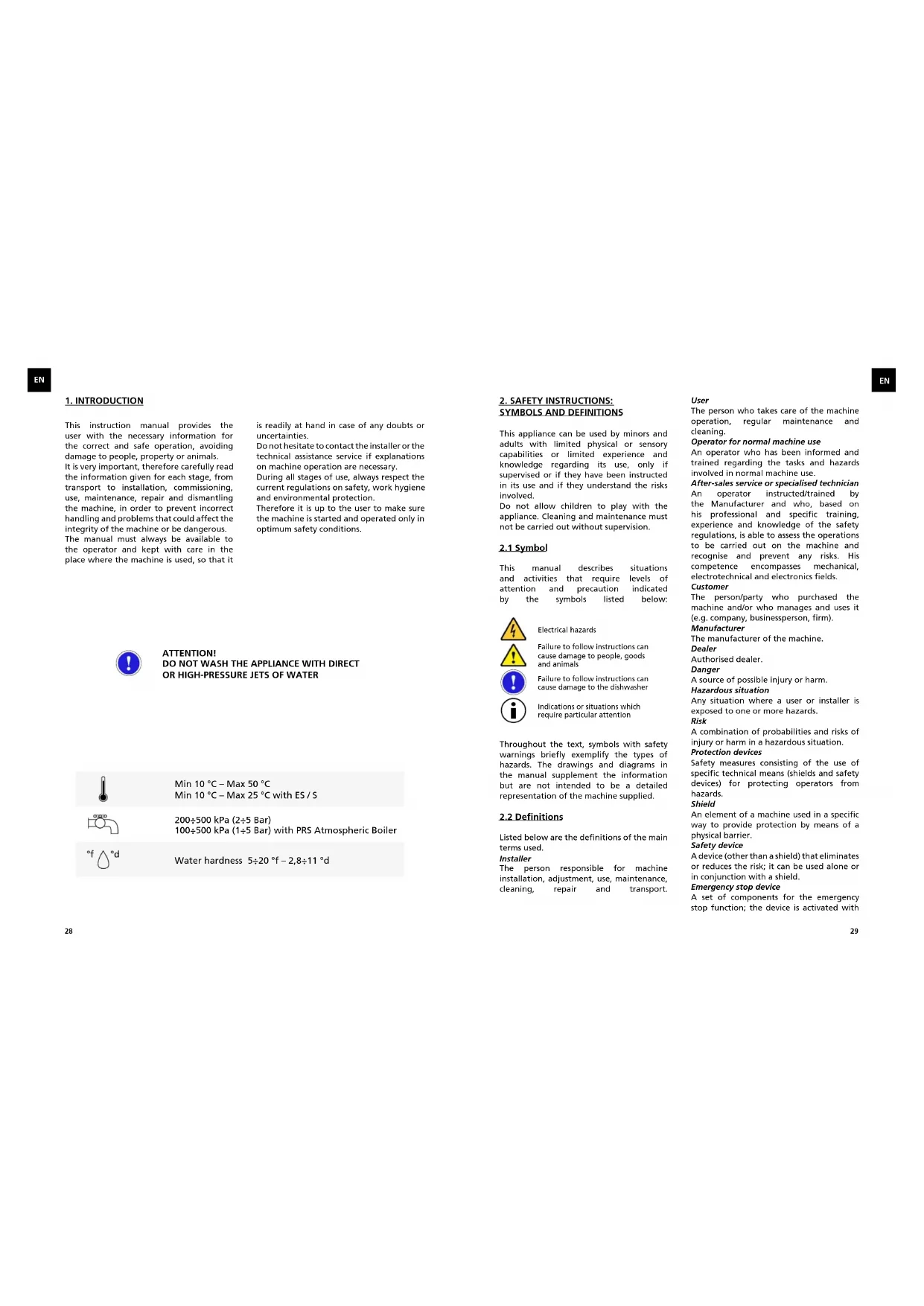
text_image
Technical diagram of a mechanical device with numbered components for identification1 - CE data plate
2 - Control panel
3 - Adjustment foot
4 - Detergent and rinse aid dosing access panel
5 - Basket support
6 - Lower wash arm
7 - Tank filters
3.1 Dishwasher versions

natural_image
3D rendering of a gray rectangular electronic device with ventilation slots and a label on the front face (no readable text or symbols)Control panel with electromechanical buttons

natural_image
3D rendering of a gray server cabinet with ventilation slots and indicator lights (no text or symbols visible)Electronic control panel with LCD display
4. INSTALLATION
During installation, connection and start up, strictly observe the following instructions.

The dishwasher must be installed by specialised personnel, in compliance with the safety regulations in force in the place of use, and following the instructions given below. Always wear personal protective equipment to carry out this type of operation.

Failure to follow these instructions will void the manufacturer's warranty on functional performance and/or damage to the machine.

If your dishwasher is found to be damaged when unpacked, contact the dealer before using it.
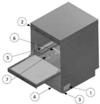
The machine must be transported to the installation site on the pallet supplied, using a pallet truck or forklift.
The location must be a professional and not a domestic environment, having industrial type wall or floor drains with drain tanks allowing an outflow of at least 3 l/sec.
Make sure the floor at the installation site is flat and can take the weight of the machine full of water with a fully loaded rack (+40% of the net weight).
4.1 Storage
Before installation the machine can be stored in a sheltered and dry place, with temperatures ranging between 5°C and 40°C. At the first installation or after long idle periods it is advisable to manually rotate the wash and rinse pump impeller (rinse pump for PRS versions) to free it from possibly adhering.
4.2 Machine handling

The machine must be handled by qualified personnel who have adequate experience and training regarding:
- the applicable safety regulations;
- the ability to identify dangerous situations and adopt the appropriate behaviour
The packed machine must be unloaded and transported with a forklift truck, making sure to slot the forks in the pallet frontally. Once on the ground, before being taken to the installation site, remove the packaging, lift the machine with the forks between the pallet and base, always in a diagonal and rear position, lift then remove the pallet and position the machine on the ground.

natural_image
3D rendering of a forklift lifting a brown box, no text or symbols visibleUsing a pallet truck (suitable for the weight to be lifted - see net weight in the data table), slot the forks under the base of the machine, placing cardboard between the pallet truck and the machine to avoid damaging it.
Do not lift the machine too high from the ground during transport and make sure the route is flat and free of any obstructions.
Before moving the machine, check the passageway size of doors and the space for steering operations.

To lift the machine safely the pallet truck forks should protrude at least 10 cm on the opposite side of the base. Wear protective gloves and safety shoes before removing the packaging.
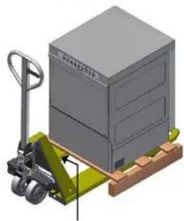
natural_image
3D illustration of a pallet jack handling a large industrial machine (no text or symbols visible)LODGE A PIECE OF PROTECTIVE CARDBOARD
4.3 Water connection

The connections must be carried out by qualified personnel in compliance with the laws in force in the place of installation.

Make sure the water supply pressure is between 100±500 kPa dynamic (1±5 Bar) for the atmospheric boiler version, and between 200±500 kPa dynamic (2±5 Bar) for the version with mains pressure boiler. This measurement must be carried out during the first water filling; if the pressure is higher, install a pressure reducer at the source. If the water has a high content of calcium and magnesium salts, with hardness >20 ^4 , it is advisable to install a water softener. Each machine is supplied with a water filling rubber hose with a 3/4" connection which must be connected to the mains water supply.

The inlet water temperature must be between 10°C and 50°C.
If the "ES" energy saving system or the "S" water softener are installed, the inlet water temperature must not exceed 25°C. The drainpipe must be connected to room's main discharge; it is advisable to insert a floor drain siphon. In the version with incorporated drain pump (option), the drainpipe already has an internal siphon (max. drain height H 800 mm).
4.4 Electrical connection

The electrical connection must be carried out by a qualified electrician, in compliance with local regulations.
Make sure the equipment is connected to an efficient earthing system and that the line voltage matches that specified on the machine's data plate.

Connect the power cable to an easily accessible 30 mA thermal-magnetic wall circuit breaker with contact gap of at least 3 mm.
Make sure the power cable has not been damaged or crushed during handling.

If necessary, it must be replaced only by an authorised installer.

Do not plug the power cable in before completing installation and fitting the cover panels.

The machine must be connected to an equipotential system, connecting the cable in the rear terminal next to the symbol.
CONNECT USING CABLE OF MIN. 10 mm² SECTION
4.5 Safety devices installed
The machine has a number of safety devices in place.
- The internal wiring has an amperometric thermal relay which stops the wash cycle in case of a pump fault.
- A micro magnetic sensor stops the wash cycle in case of accidental opening of the door.
- Manual reset thermostats switch off the heating elements in case of overheating of water.
- An overflow pipe keeps the tank water level constant.
- A safety pressure switch prevents the water inside the machine from exceeding the maximum level.

The manufacturer declines any liability for damage or injury resulting from tampering with or the non-use of these devices or due to non-compliance with the above instructions and the electrical safety regulations in force in the country of installation.
5. DESCRIPTION OF CONTROLS
The control interface is different for the various models.
5.1 Electromechanical version

text_image
1 2 3 4 5 6 7 8- ON-OFF button.
- Power ON indicator.
- Indicator displaying machine temperature ready to wash.
- Start cycle button.
- Wash cycle ON indicator.
- Select cycle button (only models with 50x50 rack).
- Activate drain pump button (option).
- Indicator displaying lack of salt (option).
5.2 Electronic version with LCD display

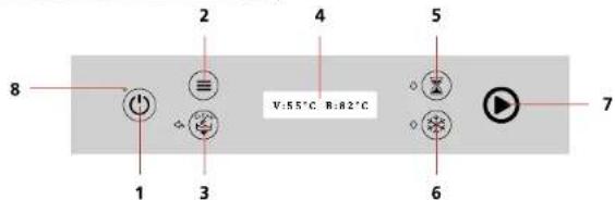
text_image
8 1 2 3 4 V:55°C B:82°C 5 6 7- ON-OFF button (press 2 seconds for ON)
- Programming menu access button (press 3 seconds).
- Drain pump/Self-cleaning button and ESC function when programming.
- LCD display.
- Select cycles and up/increase (+) function button used in programming.
- Enable cold rinse (option) and down/decrease (-) function button when programming.
- Start cycle light and Enter function when programming.
When the machine is OFF, the message "OFF" appears on the display and the power indicator 8 is red.
6. START-UP, FIRST SWITCH-ON
The user must have sufficient knowledge and experience in order to read and understand the information in this manual, interpret the signs and symbols on the machine, and carry out safety operations (e.g. turn off the main switch if water leaks are detected inside the technical compartment or in case of malfunction causing abnormal noise).
6.1 Controls and adjustments
In setting up the dishwasher, carry out the following checks:
- Make sure all the cover panels and safety devices are fitted and efficient.

text_image
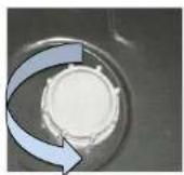
Internal view of tank MAKE SURE THE OVERFLOW AND THE PUMP FILTER ARE PROPERLY FITTED
text_image
MAKE SURE THE SURFACE FILTERS (OPTION) ARE IN PLACECheck the water connection and drain connection (see paragraph 4.3).
- Check the electrical connections and that the power supply matches that specified on the data plate.
- Make sure there are not foreign objects inside the washing chamber and tank.
6.2 First switch-on
Connect the power cable to the control panel, activate it, and open the water faucet. If present, the detergent and rinse aid dosing system must be adjusted according to the water hardness and the type of detergent and rinse aid used.
The adjustment operation will be necessary even if a water softening system is installed on the feed line. The dishwashers leave the factory with dispensers adjusted to half flow rate. To adjust the flow rate of the dispensers, use the adjustment screw as shown in the figure:
Version with electromechanical controls (standard rinse aid dispenser, optional detergent dispenser)
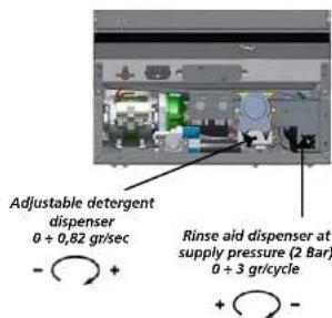
text_image
Adjustable detergent dispenser 0 + 0,82 gr/sec - + Rinse aid dispenser at supply pressure (2 Bar) 0 + 3 gr/cycle + -Version with electromechanical controls (alternative)

text_image
Adjustable detergent dispenser 0 ÷ 0,82 gr/sec Adjustable rinse aid dispenser 0 ÷ 0,12 gr/secVersion with electronic controls, LCD display

text_image
Fixed detergent dispenser 0,82 gr/sec time setting from control panel Fixed rinse aid dispenser 0,12 gr/sec time setting from control panelTo correctly dose the amounts of detergent and rinse aid follow the manufacturers' directions given on the packaging, which vary according to the type of dirt, water hardness and tank capacity. Insert the suction tubes of the dispensers, equipped with ballast, in the detergent and rinse aid containers (not supplied).

When changing the type of detergent or rinse aid, drain the tank and boiler completely, connect the dispenser suction pipes to a hot water tank and run 3 washing cycles. This operation is necessary in order to prevent the products from crystallising with possible damage to the dispenser.
6.3 Electromechanical version

text_image
1 2 3 4 5 6 7 8Close the door and start the machine by pressing the ON/OFF button (1), the Power ON indicator (2) lights up and water loading starts. Once the pre-set level is reached, the tank and boiler have been filled, and the boiler heating element starts heating the water inside. Once the set temperature is reached, the boiler heating element is deactivated and the one in the tank starts heating the water.
When the set temperature is reached, also the tank heating element is deactivated and the machine ready-to-wash indicator (3) lights up. The temperatures can be viewed on the indicators, if present.
Carry out at least 3 washing cycles to allow the detergent and rinse aid to start circulating.
For machines without detergent dispensers, manually place directly into the tank the amount of detergent recommended by the manufacturer.
filters if present, and overflow pipe and attend emptying.

Remove the plastic pump filter only once the tank has been emptied.
If the machine is fitted with a drain pump (option), press the "start drain pump button" for 3 seconds (7) to drain the machine, after removing the overflow pipe. (if present)
6.4 Electronic version with LCD display (first switch-on)
When the machine is switched on for the first time, the display shows a series of data that the installer must enter.
Once the data has been set, it will no longer be requested when switching on, unless the initial state is restored from the menu.

Exaggerating with quantities creates excessive foam that can cause the wash pump to malfunction.
Open the door, insert the rack with the dishes to be washed, select the wash cycle in minutes with the "cycle time selector" (6), if present. Press the "start cycle" button (4), the "wash cycle ON indicator" (5) lights up and the machine starts washing.
The cycle ends when the "wash cycle ON indicator" (5) goes off, and it is possible to proceed with other cycles.
At the end of service always drain the water in the tank: open the door, remove surface
ON-OFF BUTTON (PRESS 2 SECONDS FOR ON)
UP BUTTON
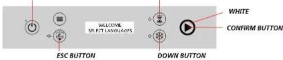
text_image
WELCOME SELECT LANGUAGRS ESC BUTTON DOWN BUTTON WHITE CONFIRM BUTTON
text_image
SELECT LANGUAGE ENGLISH ← EDIT/CONFIRM BUTTONSELECTABLE LANGUAGES:ITALIANO-ENGLISH-FRANÇAIS-ESPAÑOL-DEUTSCH-PORTUGUES-NEDERLANDS

text_image
ELECTRONIC CODE XXXX CONFIRM BUTTONThe electronic code is preset by the manufacturer

text_image
WATER HARDNESS 25 °F 14 °F EDIT/CONFIRM BUTTONAfter changing the hardness value with the up/down buttons, press the confirm button

text_image
PREFLOAD DISPENSERS1 OFF EDIT/CONFIRM BUTTONAfter editing with up/down button, change from "OFF" to "ON" and confirm to follow through.

text_image
INSERT PIPES IN THE TANKS CONFIRM BUTTON
text_image
PRELOAD DETERGENT CONFIRM BUTTONPressing the confirm button activates the detergent dispenser for a given time and the button blinks white. Finally, press the confirm button.

flowchart
graph LR
    A["ESC BUTTON"] --> B["PRELOAD RINCE, AID"]
    B --> C["CONFIRM BUTTON"]
Pressing the confirm button activates the rinse aid dispenser for a given time. The button blinks white. Finally, press the confirm button and the machine goes to the tank filling phase. Pressing the "ESC" button, returns to the previous screen.

text_image
ON-OFF BUTTONBy pressing the "ON-OFF" button, the first switch-on sequence ends, and the machine is turned off.
MACHINE WATER LOADING SCREEN

text_image
FILLING YELLOW SQUARES SCROLLINGMACHINE HEATING ELEMENTS SCREEN

text_image
V: 55°C B: 82°C YELLOWDuring heating, the button indicated is yellow. If the wash cycle is launched with cold tank, the cycle does not start, and a message appears on the display.

text_image
COLD TANK V: 40°C B: 82°C YELLOWWith the START button green, the temperatures have been reached and the machine is ready for wash cycle.
START WASH CYCLE
Select the cycle. The wash cycle can be launched by pressing the START button, with door closed, tank filled, and hot water (green START button).

text_image
Glue 1.20 □□□□ SELECT CYCLE EX. GLASSES START BLUEWhen the wash cycle is launched, the start button turns blue, and the cycle time countdown begins, with the horizontal bar scrolling. The running cycle can be stopped by pressing the START button. If the door is opened for more than 10 seconds during the wash cycle, the cycle is reset.

text_image
END CYCLE GREEN BLINKINGAt the end of the wash cycle, the START button blinks green until the door is reopened, and the display shows the message "END CYCLE"

text_image
RED LED ON-OFF BUTTON OFFTo turn the machine off, press the ON-OFF button twice. The led will become red.
6.5 Electronic version with LCD display
text_image
8 1 2 3 4 V:5.5°C, B:8.2°C 5 6 7Close the door and turn the machine on by pressing the "ON/OFF" button (1) for 2 seconds, the LCD display (4) will light up and indicate the water loading phase. After filling, the detergent and rinse aid dispensers inject the dose as established by the parameters relevant to the set wash cycle.

Exaggerating with quantities creates excessive foam that can cause the wash pump to malfunction.
Once the pre-set level has been reached, the tank and boiler are full, the boiler heating element starts heating the water inside (7 yellow) and the relative temperature blinks on the display. Once the set temperature is reached, the boiler heating element is deactivated, while the one in the tank starts heating the water (7 yellow) and the temperature blinks on the display. See paragraph 6.4. Once the set temperature is reached, the tank heating element is also deactivated.
The START button (7) turns green when the minimum tank and boiler temperatures are reached. The machine is now ready to carry out a wash cycle. Open the door, insert the rack with items to be washed, select the wash cycle with the "select times button" (5), press the "start cycle button" (7). The "wash cycle On indicator" turns blue, and the machine starts washing. The cycle ends when the "wash cycle On indicator" (7) blinks green and "END CYCLE" appears on the display, hence it is possible to remove the rack and to proceed with other cycles.
It is possible to activate the automatic cycle start, to take action upon closing the door, by setting the "Automatic Cycle" parameter to the value "ON" from the programming menu. The setting remains active until the next change. Once the parameter is enabled by pressing the "select times button" (5) for two seconds it is deactivated or activated as desired.
At the end of service, always drain the water in the tank: open the door, remove surface filters and the overflow pipe (if present) and attend emptying.

Remove the plastic pump filter only after emptying.
If the machine is fitted with a drain pump (option), keep the "drain pump button" (3) pressed, to empty the tank.
6.6 Cleaning function
At the end of the service, a final cleaning cycle can be activated manually. With the machine switched on and door closed, press and hold the "drain pump button" (3) for 3 seconds. The display will show "REMOVE OVERFLOW PIPE!" and "TANK DRAINING" and the button 7 turns purple. Open the door and remove the overflow pipe (if present). When the tank is empty the display will show "SELF-CLEANING" and after a short pause the solenoid valve or the rinse pump (PRS versions) will be activated for a set time, followed by draining. After the draining time, the machine will go to OFF mode. If the door is left open after pressing the "drain pump button" (3), the machine will only drain the tank, and remains in standby for five minutes, after which it will go to OFF mode without cleaning.

text_image
3 SELF-CLEANING PURPLE6.7 Cold rinse function (option)
A cold rinse can be carried out at the end of the full wash cycle; the function is activated by pressing button 6 for 3 seconds and LED 9 (blue) will light up. At the end of the rinse cycle, after a pause, button 7 will turn light blue and the display will show the message COLD RINSE.

text_image
COLD RINGE LIGHT BLUE 6 96.8 Energy Saving function
Green function: This function allows the boiler and tank temperatures to be lowered during periods of machine inactivity, by controlling the temperatures. During this phase, the display will show the message "GREEN FUNC. ON."
At the start of the wash cycle the heating elements resume their standard activity.

text_image
GREEN FUNC. ON V:55°C B:82°C GREEN6.9 Programming (user)
With the machine OFF, press the "access programming menu" button (2) for 3 seconds and confirm with the "start cycle" button (7). With the buttons 5 (+) and 6 (-), move to the parameter to modify and press the "start cycle" button (7) to enable the edit. Using the buttons 5 (+) and 6 (-), select the desired value and confirm by pressing the "start cycle" button (7) again. Press the "ESC" button (3) twice to exit programming. In the programming menu the user can change the following values

text_image
1 2 3 MENU USER MENU 5 6 7 WHITEIn the programming menu the user can change the following values
| Description | Value | Default parameters |
| Language IT,UK,FR,ES,DE | PT,NL ENGLISH | |
| Temperature °C + °F °C | ||
| Acoustic signal Off + On Off | ||
| Initial message Off + On Off | ||
| Initial text *****. | ||
| Brightness 15 ÷ 90 % 75 % | ||
| Automatic cycle | Off + On Off | |
| Total cycles | 0 ÷ 999999 | - |
6.10 Errors that can be viewed on the display

text_image
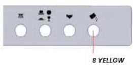
1 3 ALARM 62 HEATING ROBER RED STEADY/BLINKINGList of ERRORS that can be displayed, with the button (7) red steady/blinking:
| Alarm number | Display Message | Description | User checks | Installer checks |
| Alarm 01 | TANK FILLING | TANK not filling | - Tap does not supply water;- Overflow pipe placed incorrectly or not inserted;- Rinse arm nozzles clogged;- Inlet pipe constricted | - Faulty or clogged solenoid valve;- Clogged boiler;- Faulty pressure switch;- Clogged air gap; |
| Alarm 02 | BOILER HEATING | BOILER not heating | Request technical assistance | - Faulty heating element- Check possible contactor |
| Alarm 03 | TANK HEATING | TANK not heating | Request technical assistance | Faulty heating element |
| Alarm 04 | TANK DRAINING | No TANK draining within time-out | - Check cleaning of filters;- Make sure the drain hose is not blocked or pinched; | Drain pump blocked by a foreign body or faulty |
| Alarm 05 | BOILER FILLING | BOILER not filling | - Tap does not supply water;- Constricted inlet pipe | - Faulty or clogged solenoid valve;- Faulty pressure switch |
| Alarm 06 | BOILER PROBE | Boiler probe temperature outside range | Request technical assistance | Check boiler temperature probe |
| Alarm 07 | TANK PROBE | Tank probe temperature outside range | Request technical assistance | Check tank temperature probe |
| Alarm 08 | Thermostat TIME-OUT | Thermostat time out before rinse | Request technical assistance | - Faulty boiler heating element;- Check possible contactor |
| Alarm 09 | BOILER SAFETY SW | Boiler safety thermostat intervention | Request technical assistance | Check boiler safety thermostat |
| Alarm 10 | TANK SAFETY SW | Tank safety thermostat intervention | Request technical assistance | Check tank safety thermostat |
| Alarm 12 | PANEL CONNECTION | No communication with circuit board | Request technical assistance | Check circuit board cable connections |
| Alarm 13 | PARAMETER ERROR! | The parameters have been compromised | Request technical assistance | Carry out initial installation sequence by entering the four-digit machine code |
| Alarm 15 | SERVICE WARNING | The number of cycles for carrying out maintenance have been reached | Request technical assistance | Carry out a dishwasher maintenance/check |
- Errors 01, 05, 09, 10, 12 are critical (button 7 is fixed red) and shut down the machine completely. To reinstate the machine, request technical assistance. To reset these errors, the PCB must be switched off and then on again (ON-OFF button 1).
- With errors 02, 03, 04, 06, 07 and 08 button 7 continues to blink red until the error is reset (press button 3). If the problem persists, request technical assistance.
- With error 13 the machine goes to the first installation sequence. It is necessary to request the assistance of a technician who must enter the machine model code.
7. AUTOMATIC WATER SOFTENER (OPTIONAL)
Optional automatic water softener is available for both machines with electromechanical buttons and those with electronic control panel (with LCD display). The dishwasher is fitted with an automatic water softener whose operation is managed directly by the PCB.
7.1 Operation
During the first loading, and at each wash cycle, the water entering passes through the water softener reservoir containing ion exchange resins. These combine with calcium and magnesium ions, responsible for limescale residues, and make them inert.
Due to gradual saturation the action of the resins tends to weaken over time but can be restored thanks to the addition of saline water. This process is called "regeneration". Therefore the water softener also has a 1 kg capacity salt container, which must be periodically filled. A sensor checks the salt level and, if insufficient, the message "SALT FINISHED!" is displayed followed by an alarm sound, or the warning light comes on (8 for version with electromechanical buttons.

text_image
SALT FINISHED! BLINKINGFrom this stage on, even if the dishwasher is able to operate, the water softener is not treating the water. Due to the action of the water softener, the hardness of the water used for the wash cycles is reduced to about 6-8 °f. To maintain the effectiveness of the resins and to keep the water hardness level constant, the dishwasher carries out a regeneration after a number of wash cycles, established according to the initial water hardness settings(see Table 1). Regeneration lasts 120 seconds and is done at the end of each initial filling and during the wash cycle with the chosen interval.
If a wash cycle with a shorter time has been set, during regeneration this will last 120sec + 20sec (rinse); during the 120 seconds, for all the additional time due to regeneration, the display will show the message "SELF REGENERAT".

text_image
SELF REGENERAT. BLUE7.2 Installation
The dishwasher with automatic water softener comes with the water softening function already activated and set for a hardness of 25 °f.
For this value, regeneration of the resins occurs every 20 cycles in the electromechanical version and 24 cycles in the electronic version. For different hardness values, the frequency of regeneration must be changed as indicated in Table 1. To change the regeneration frequency, request technical assistance. Initial filling of salt in the container: unscrew the cap, fill the container with 2 glasses of hot water, then add 1kg of kitchen rock salt. Tighten the cap, making sure to remove any residual salt on the outside.
7.3 Maintenance
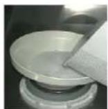
Maintenance of the automatic water softener system consists of filling the salt container whenever the message "SALT FINISHED!" appears on the LCD display, or when the indicator light comes on (in versions with electromechanical buttons). Only use kitchen rock salt: unscrew the cap inside the wash tank and carefully add 1 kg of salt, using the special funnel provided and facilitating the outflow of water contained in the reservoir below.
Make sure the salt does not spill, and do not exceed the recommended amount. After adding the salt, add 2 glasses of hot water in order to facilitate the dissolving of salt, clean the gasket, close the cap properly, eliminate any residual salt, remove the overflow pipe, if present and rinse the tank thoroughly.

Residual salt that is not removed can cause corrosion of the steel!
After filling, the dishwasher is ready for normal operation.

| INLET WATER HARDNESS SETTING | REGENERATION INTERVAL (CYCLES) | RECOMMENDED DETERGENT WITHOUT WATER SOFTENER | RECOMMENDED RINSE AID WITHOUT WATER SOFTENER | RECOMMENDED DETERGENT WITH WATER SOFTENER | RECOMMENDED RINSE AID WITH WATER SOFTENER |
| 40 °F | 9 | DETERGENT FOR HARD WATER | RINSE AID FOR HARD WATER | DETERGENT FOR SOFT WATER | RINSE AID FOR SOFT WATER |
| 39 °F | 12 | ||||
| 38 °F | |||||
| 37 °F | |||||
| 36 °F | |||||
| 35 °F | 16 | DETERGENT FOR MEDIUM HARD WATER | |||
| 34 °F | |||||
| 33 °F | |||||
| 32 °F | |||||
| 31 °F | 20 | ||||
| 30 °F | RINSE AID FOR MEDIUM HARD WATER | ||||
| 29 °F | |||||
| 28 °F | |||||
| 27 °F | 24 | ||||
| 26 °F | |||||
| 25 °F | |||||
| 24 °F | |||||
| 23 °F | 28 | ||||
| 22 °F | |||||
| 21 °F | |||||
| 20 °F | |||||
| 19 °F | 32 | DETERGENT FOR SOFT WATER | RINSE AID FOR MEDIUM HARD WATER | ||
| 18 °F | |||||
| 17 °F | |||||
| 16 °F | |||||
| 15 °F | 36 | RINSE AID FOR SOFT WATER | |||
| 14 °F | |||||
| 13 °F | |||||
| 12 °F | |||||
| 11 °F | WATER SOFTENER NOT NECESSARY | ||||
| 10 °F | |||||
| 9 °F | |||||
| 8 °F | |||||
| 7 °F | |||||
| 6 °F | |||||
| 5 °F |
8. DAILY USE
Before using the machine it is advisable to proceed as indicated in paragraph 6.1 regarding its state.
Solid waste must be removed from items before being washed.
In case of encrustations, soak items before introducing them.
When putting items in the rack supplied, make sure to arrange them so that the dirtiest part receives water from the lower wash arms yet without retaining water inside them.

Each time the cycle ends, open the door and wait a few moments to allow the load to dry and cool naturally. Wear protective gloves before touching the load; it may still be very hot.
Run a couple of cycles without loading before using the machine for the first time, to clean the inside and ducts of any impurities.
It is advisable to change the tank water every 25 washes or twice a day.

In machines with electronic display, it is possible to set the number of cycles after which programmed or forced draining is to be carried out. Too high temperatures can cause starch residues to stick to items.

Be careful not to touch the heating element inside the tank upon tank draining and removing the overflow pipe, as it may still be very hot.

At the end of the self-cleaning cycle, with the tank empty, clean the filters with running water and remove the residuals of dirt with a non-metallic brush.
Place the filters and any other utensils back inside the tank and close the door.
9. CARE AND MAINTENANCE
Check the detergent and rinse aid in the respective containers every day.
Do not clean the appliance with direct or high-pressure jets of water.
Do not use corrosive products such as sodium hypochlorite or acids.
If the feed water has a high content of calcium and magnesium salts, it is advisable to carry out regular descaling with appropriate products in the correct doses and concentrations.

Rinse thoroughly and dry the internal parts where the descaling product was applied!
In the event of prolonged idle periods (several weeks), it is advisable to run the dishwasher with clean water for 3 cycles before starting the wash.
Before proceeding, make sure the wash and rinse pump rotate freely.
To do this, use a screwdriver in the special slot on the motor shaft (ventilation side). In the electronic version, when the set number of cycles is reached, the display will show the message "SERVICE WARNING" to prompt contacting technical assistance.
- TROUBLESHOOTING
| PROBLEMS | POSSIBLE CAUSES AND CURES |
| The control panel/display does not light up | A) Make sure the wall power switch is turned on and that the fuses are not blown;B) Make sure the plug is properly inserted in the socket. |
| The tank does not fill with water | A) Check the supply water and that the shutoff valve is open.B) Make sure the pressure switch is not out of calibration or out of order.C) Check proper operation of the solenoid filling valve and internal filter.D) Make sure the overflow is fitted in place. |
| Water filling does not stop when the level is reached | A) Make sure the pressure switch is not out of calibration or out of order.B) Check proper operation of the solenoid valve.C) Make sure the inside of the air trap is not dirty |
| Inadequate washing results | A) Make sure the detergent used is the correct type and in the right dose (as recommended by the manufacturer).B) Make sure the impeller nozzles are not clogged.C) Make sure the tank water temperature is at least 55°C.D) Make sure the pump filter is not clogged by impurities.E) The wash cycle is too short. Repeat the cycle. |
| Inadequate tank temperature | A) Check that the thermostat is not out of calibration, faulty or incorrectly set (electromechanical machines).B) Check the temperature setting on the boardC) Check proper operation of the tank heating element. |
| Unsatisfactory rinsing A) | Check the water supply pressure.B) Make sure the nozzles are not clogged with limescale.C) Check proper operation of the solenoid valve.D) Check proper operation of the supplementary pump (if present).E) Make sure there is rinse aid in the tankF) Check the rinse water temperature (80÷85°C) |
| Rinse temperature too low | A) Make sure the thermostat is not out of calibration, faulty or incorrectly set.B) Check the temperature setting on the boardC) Check if the safety thermostat has intervened and verify related causes.D) Check proper operation of the heating element.E) Make sure the coil of the contactor for the boiler heating element is not disconnected. |
SOMMAIRE
text_image
Technical diagram of a mechanical device with numbered components for identificationnatural_image
3D rendering of a gray rectangular electronic device with ventilation slots and a label on the front face (no readable text or symbols)natural_image
3D rendering of a gray server cabinet with ventilation slots and indicator lights (no text or symbols visible)natural_image
3D rendering of a forklift lifting a brown box, no text or symbols visiblenatural_image
3D illustration of a pallet jack carrying a large gray industrial box (no text or symbols visible)INTERPOSER UN CARTON DE PROTECTION
4.3 Raccordement hydraulique

text_image
Technical diagram of a mechanical device with numbered components for identificationnatural_image
3D rendering of a gray rectangular electronic device with ventilation slots and indicator lights (no text or symbols visible)natural_image
3D rendering of a gray server cabinet with ventilation slots and ventilation ducts (no text or symbols visible)natural_image
3D illustration of a forklift lifting a brown box (no text or symbols visible)
natural_image
3D rendering of a gray industrial pallet jack with green handle and wooden base (no text or symbols visible)text_image
Technical diagram of a mechanical or electronic device with numbered components for identificationnatural_image
3D rendering of a gray industrial cabinet or rack unit with no visible text or symbolsnatural_image
3D rendering of a gray office cabinet with ventilation slots and doorways (no text or symbols visible)natural_image
3D rendering of a forklift lifting a brown box, no text or symbols visiblenatural_image
3D rendering of a gray industrial pallet jack with wheels and a wooden base (no text or symbols visible)natural_image
3D mechanical component diagram showing internal structure with no visible text or symbolstext_image
Technical diagram of a mechanical device with numbered components for identificationnatural_image
3D rendering of a gray server cabinet with ventilation slots and top panel (no visible text or labels)natural_image
3D rendering of a gray server cabinet with ventilation slots and ventilation grilles (no text or symbols visible)natural_image
3D illustration of a forklift lifting a brown box (no text or symbols visible)natural_image
3D rendering of a gray industrial pallet jack with green handle and wooden base (no text or symbols visible)text_image
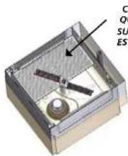
Vist CERTIFIQUEVista do Interior
da cuba
CERTIFIQUE-SE DE QUE O TUBO
DE NÍVEL DA ÁGUA E O FILTRO
DA BOMBA ESTÃO INSERIDOS
CORRETAMENTE
text_image
C Q S E S E Snatural_image
Interior view of a computer case showing internal components like CPU, memory, and drive slots (no text or labels visible)Doseador de detergente
regulável
0 ÷ 0,82 gr/seg

text_image
V: 55°C B: 82°C COR AMARELOtext_image
FUNÇÃO GREEN ON V.55°C 8.82°C COR VERDEtext_image
Technical diagram of a mechanical device with numbered components for identificationnatural_image
3D rendering of a gray industrial cabinet or storage unit with ventilation slots and control panel (no visible text or symbols)natural_image
Isometric illustration of a gray server cabinet with ventilation slots and ventilation duct (no text or symbols)natural_image
3D rendering of a forklift lifting a brown box, no text or symbols visibleThe Manufacturer reserves the right to change without notice the characteristics of the machines presented in this publication.