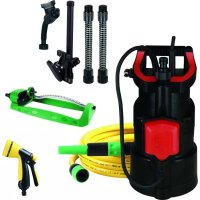
DrainPress 320024 Set - Pump T.I.P. - Free user manual and instructions
Find the device manual for free DrainPress 320024 Set T.I.P. in PDF.


| Product type | Submersible pump |
| Brand | T.I.P. |
| Model | DrainPress 320024 Set |
| Mains voltage | 230 V~ / 50 Hz |
| Power consumption | 400 Watts |
| Protection class | IPX8 |
| Discharge connection | 26.44 mm (3¼"), male thread |
| Max. flow rate | 3 200 l/h |
| Max. pressure | 2.4 bar |
| Max. delivery head | 24 m |
| Max. immersion depth | 7 m |
| Max. solids size | 2 mm |
| Max. liquid temperature | 35 °C |
| Connection cable length | 10 m |
| Net weight | approx. 4.7 kg |
| Dimensions (L x W x H) | 16 x 15.5 x 30.0 cm |
| Min. self-priming level | 45 mm / 40 mm |
| Min. suction level | 4 mm / 1 mm |
| Max. starts per hour | 30 |
| Delivery contents | Pump, connection, instruction manual |
| Main functions | Pumping of clear or slightly dirty water for pools, tanks, irrigation, drainage (flat suction) |
| Maintenance and cleaning | Rinse with clear water; disassemble the foot for stubborn dirt |
| Safety | Motor thermal protection; requires a 30 mA residual current device; prohibited to use when people are in the water |
| Spare parts and repairability | Available at www.tip-pumpen.de; repairs by qualified after-sales service |
Frequently Asked Questions - DrainPress 320024 Set T.I.P.
User questions about DrainPress 320024 Set T.I.P.
0 question about this device. Answer the ones you know or ask your own.
Ask a new question about this device
Download the instructions for your Pump in PDF format for free! Find your manual DrainPress 320024 Set - T.I.P. and take your electronic device back in hand. On this page are published all the documents necessary for the use of your device. DrainPress 320024 Set by T.I.P..
USER MANUAL DrainPress 320024 Set T.I.P.
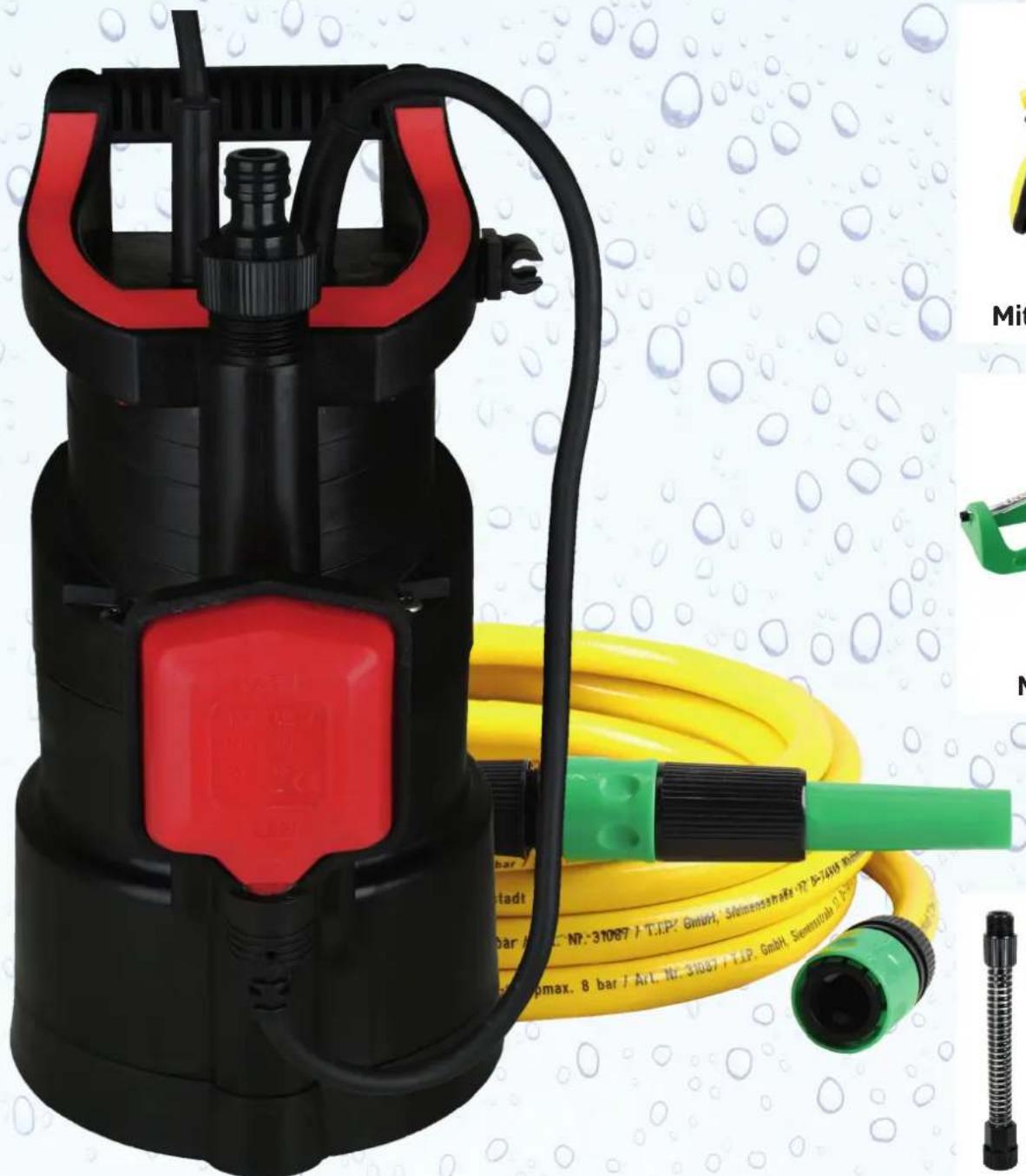
DrainPress 3200/24 Set
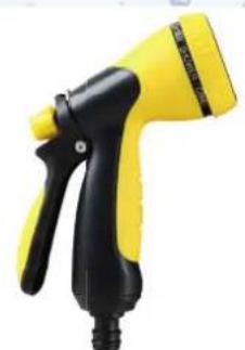
Mit Gartenbrause
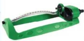
Mit Beregner
Operating Instructions Submersible pump

Congratulations for buying your new device from T.I.P.!.
Like all our products, this one, too, was developed using the latest technological knowledge. The device was manufactured and assembled on the basis of state-of-the-art pump technology using most reliable electrical or electronic components which ensure a high level of quality and a long life of your new product.
Please read through these operating instructions carefully to make sure that you can fully benefit from all features.
Some explanatory illustrations can be found at the end of these operating instructions.
We hope you will enjoy your new device!
Table of contents
- General safety information 1
- Range of use 2
- Technical Data 2
- Scope of delivery 3
- Installation 3
- Electrical connection 4
- Putting into operation 5
- Maintenance and troubleshooting 5
- Warranty 7
- How to order spare parts 8
- Service 8
Annex: Illustrations
1. General safety information
Please read through these operating instructions carefully and make yourself conversant with the control elements and the proper use of this product. We shall not be liable in the case of damage caused as a result of the nonobservance of instructions and provisions of the present operating instructions. Any damage caused as a result of the nonobservance of the instructions and regulations contained in the present operating instructions shall not be covered by the warranty terms. Please keep these operating instructions in a safe place and hand them on together with the device should you ever dispose of it.
Persons not conversant with the contents of these operating instructions must not use this device.
The pump must not be used by children.
The pump may be used by persons with reduced physical, sensory or mental capabilities or lack of experience and / or knowledge if they have been supervised or instructed in the safe use of the equipment and have understood the resulting hazards.
Children are not allowed to play with the device.
Keep the appliance and its cord out of reach of children.
The pump must not be used when people or animals are in the water.
The pump must be supplied through a residual current device (RCD) having a rated residual operating current not exceeding 30mA .
If the supply cord is damaged, it must be replaced by the manufacturer, its service agent or similarly qualified persons in order to avoid a hazard.
Disconnect the device from the power supply and let it cool down before cleaning and maintenance is performed and before the device is stored.
Notes and instructions with the following symbols require particular attention:

Any nonobservance of these instructions involves the danger of bodily harm to people and/or damage to property.
Any nonobservance of this instruction bears the risk of an electrical shock which may cause damage to persons or property.
Please inspect the device for damage occurred during transportation. In case of damage, the retailer has to be informed immediately, at the latest within 8 days after the date of purchase.
2. Range of use
These for special applications developed submersible multistage pumps from T.I.P. are highly efficient electrical pumps for discharging clear, clean or moderately dirty water containing solids up to the maximum size specified in the technical details. These high-quality products with their convincing performance data were developed for the multiple purposes involved with irrigation, draining and pumping liquids from one place to another.
The typical ranges of application of DrainPress pumps include: draining of pools, basins and storage containers as well as the operation of irrigation systems and draining from rooms (thanks to low suction function). This pump is suitable for stationary or temporary installations.
This product is intended for private use in the home area and not for commercial or industrial purposes or for continuous circulating.
The device is not suitable for use in swimming pools when people or animals are in the water or for installation in public water mains.
The pump is not suitable for use in table-top fountains, aquariums or similar ranges of use.

The pump is not suited to discharge saltwater, faeces, inflammable, etching, explosive or other hazardous liquids. Please observe the max. temperature of the liquids to be discharged stated in the technical data.

Inside the pump, lubricants are used which may contaminate the liquids being discharged in case of any improper operation or damage of the device. The lubricants used are biologically degradable and non-hazardous to health.
3. Technical Data
| Model | DrainPress 3200/24 6H |
| Mains voltage / frequency | 230 V~ / 50 Hz |
| Nominal performance | 400 Watt |
| Protection type | IPX8 |
| Pressure port | 26,44 mm (¾") male |
| Max. flow rate (Qmax)1) | 3.200 l/h |
| Max. pressure | 2,4 bar |
| Max. delivery height (Hmax)1) | 24 m |
| Max. submersion depth ∇ | 7 m |
| Max. size of the solids being pumped | 2 mm |
| Max. fluid temperature (Tmax) | 35 °C |
| Max. cut-in frequency in one hour | 30, evenly distributed |
| Length of connection cable | 10 m |
| Cable type | H05RN-F |
| Weight (net) | ~ 4.7 kg |
| Min. self-priming level (A)2) | 45 mm / 40 mm |
| Min. suction level (B)2) | 4 mm / 1 mm |
| Cut-in level (C)2) | 600 mm - 250 mm |
| Cut-out level (D)2) | 60 mm - 170 mm |
| Dimensions (L x D x H) | 16 x 15,5 x 30,0 cm |
| Item no. | 30181 |
1) The values were determined with free, unreduced outlet.
2) The values between brackets refer to the illustrations given at the end of these operating instructions.
4. Scope of delivery
The scope of the delivery of this product includes:
One pump with connection cable, an outlet element, one operating manual.
Please verify that the scope of delivery is complete. Depending on the purpose of the application, additional accessories may be necessary (please refer to the chapters titled "Installation" and "How to order spare parts").
If the pump is to be used for example as rain barrel pump, corresponding accessories can be ordered in our spare parts shop.
If possible, keep the packing until the warranty period has expired. Please dispose of the packing materials in an environmental-friendly manner.
5. Installation
5.1. General installation information

During the entire process of installation, the device must not be connected to the electrical mains.
The pump and the entire connection system have to be protected from frost.
All connection lines have to be perfectly tight since leaking lines may affect the performance of the pump and cause considerable damage. If required, please use a suitable sealant to make the installation airtight. When tightening threaded connections, please do not apply excessive force which may cause damage.
When laying the connection pipes, you should make sure that the pump is not exposed to any form of weight, vibration or tension.
5.2. Installation of the pressure line
The pressure line conveys the liquids to be discharged from the pump to the point of withdrawal. To avoid dynamic flow losses, one should use a pressure line having at least the same diameter as the pressure port (1) of the pump.
To facilitate installation, a quick coupling connector for direct connection of a garden hose is included.
5.3. Stationary installation
If the unit is used in a stationary installation, rigid pipes have proven to be the ideal choice for the pressure lines. In this type of installation, we recommend that you incorporate a check valve (non-return valve) in the pressure line immediately following the pump outlet so that no liquid will flow back after the pump cuts out. To facilitate maintenance work, we also recommend the installation of a stop cock valve downstream of the pump and check valve. This arrangement is beneficial in that closing the stop cock will prevent the pressure line from running dry after the disassembly of the pump.
5.4. How to set the floating switch

Please make sure that the pump will cut out as soon as the water level decreases and the floating switch has reached the cut-out level.
Also, it must be made sure that the floating switch can move freely.
The pump is equipped with a floating switch (2) causing the unit to cut in or out automatically as a function of the water level as soon as the water level has reached, or dropped below, the cut-out level, the pump will cut out. When the water level reaches or raises above the cut-in level, the pump will resume operation. The cut-in and cut-out levels can be adjusted by shortening or lengthening the freely movable cable (3) of the floating switch. The length of the cable can be set at the cable duct (4) located at the carrying handle (5) of the pump. In this regard, the relevant part is the freely movable part of the cable leading from the cable duct to the floating switch. If this length increases, the cut-out level will decrease, and the cut-in level will augment. Vice versa, if its length decreases, the cut-in level will increase whereas the cut-out level will be lowered.
Shall the pump continue to suck beyond the automatic cut-out level, the flow switch has to be operated manually, e.g. by holding it in upright position. Therefore you have to take the cable of the float switch from the side cable guide (4). Then lock the float switch in the holder provided on the front pump (13) by sliding the switch from above vertically in the bracket so that the cable points downward. Only in this operation mode, the minimum suction height can be reached as listed in the tec. data box. In this condition the pump has to be under constant supervision to avoid dry running.
5.5. Use as low suction pump
If you want to use the excellent low suction function of the pump (minimal suction level 1 mm) - for example, for drainage of rooms - you need to remove the dirt guard in front of the suction port at the pump.
Unscrew the 3 screws (12) and remove the grid. In this operation mode you must consider the following:
a) Only clear water with a max. particle size of 0.5mm can be pumped. Since no more dirt guard is mounted there is a risk that the pump is clogged or blocked and the impellers are damaged.
b) To reach the minimum suction level the pump must operate in manual mode, this means the float switch must be fixed in upright position (see above). This means that the pump will run permanently as long as it is connected to the electrical mains. This increases the risk of dry running which may cause severe damage to the unit as a result of overheating. So please do make sure that the pump is only operating as long as there is enough liquid left to be discharged by it.
c) When starting the pumping-out the water level must be at least 45mm (see min. self priming level) so that the pump housing is vented.
d) By dismantling the dirt protective grid and the screws the max. flow rate is reduced about 30% .
In normal operation, you should use the pump always with mounted dirt protective grid to avoid-pollution and damage to the pump.

In manual operation mode (with fixed float switch) the pump has to be under constant supervision to avoid dry running.
5.6. How to position the pump
When positioning the pump, please make sure that the max. submersion depth indicated in the technical data will not be exceeded. Likewise, please make sure that the minimum self-priming level is not fallen short of. If everything is properly set, the water level may decrease down to the minimum suction level once the pump is operating.
Please position the pump on solid ground. Avoid placing it on lose stones or sand. When positioning the pump, please do make sure that the pump cannot tip over or sink into the ground with its intake openings. The penetration of sand, mud or comparable matters is to be avoided.
To position, lift up or carry the pump, please use only the carrying handle. If required for lowering or raising the pump, you may connect a suitable lowering rope to the carrying handle. In no case must the pressure hose, the mains cable or the cable of the floating switch be used to position, to lift up or to carry the pump.
6. Electrical connection
The unit is equipped with a mains connection cable and a mains plug. It must only be replaced by qualified staff to avoid any danger. Please do not use the mains connection cable to carry the pump, and do not use this cable to pull off the plug from the socket, either. Protect the mains connection cable and mains plug from heat, oil or sharp edges.

The values stated in the technical details have to correspond to the mains voltage. The person responsible for the installation has to make sure that the electrical connection is earthed in compliance with the applicable standards.
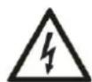
The electrical connection has to be equipped with a highly sensitive residual current circuit-breaker (FI switch): = 30mA (DIN VDE 0100-739).

Only use an extension cable with a cable section (3 × 1.0 ~mm^2) and rubber sheath which at least corresponds to that of the unit's own connection cable (see "Technical data", cable type) and which is labelled with the relevant abbreviation according to the VDE (German Association for Electrical, Electronic & Information Technologies). The mains plug and other connections must be splashproof.
7. Putting into operation

Nobody must be in the water while the pump is running.

The pump must only be operated in the performance range indicated on the type plate.

Dry-running - i.e. operating the pump without discharging water - is to be avoided since the absence of water may cause the pump to run hot. This may cause considerable damage on the device.

Please make sure that the electrical plug connections are in the flood-proof area.

As long as the device is connected to the electrical mains, one must never reach with one's hands into the opening of the pump.
Please inspect the pump visually prior to each use. This applies in particular to the mains connection line and the mains plug. Make sure that all screws are firmly tightened, and verify the perfect condition of all connections. A damaged pump must not be used. In any case of damage, the pump has to be inspected by qualified service staff.
To put the unit into operation, please plug the mains plugs into a 230V AC socket. If the water level has reached or exceeded the cut-in level, the pump will start to run immediately.
To stop the operation of the pump, please pull the mains plug off the socket.
The negligible water leakage at the lateral venting bore hole - about 10cm below the pressure port - is inherent to the design of the device and provides for both venting at the start-up of the pump and for temporary pressure relief when the stopcock is closed, respectively.
The electrical pumps of the T.I.P. DrainPress series are equipped with an integrated thermal motor protection feature. In the case of overload, the motor will switch off independently and on again after cooling down. For possible causes and their elimination, please refer to the "Maintenance and troubleshooting" section.
8. Maintenance and troubleshooting
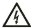
Prior to carrying out any maintenance work, the pump must be separated from the electrical mains. If you fail to separate the unit from mains, there is a risk of an inadvertent start of the pump.

We decline any liability for damage caused by inappropriate repair attempts. Any damage caused by inappropriate repair attempts will avoid all warranty claims.
Observing the conditions of use and the ranges of application of the present device will reduce the risk of possible operational malfunction and contribute to extend the lifetime of your unit. Sand and other abrasive matters contained in the liquid discharged will speed up the process of wearing and tearing and accelerate the drop in performance.
If the unit is operated properly, it will not require any maintenance. Where applicable, you may clean the hydraulic part from sediments and dirt. This can be done by counter-flushing the unit with clear water using a hose to be connected through the pressure port of the pump. To remove tenacious dirt, the foot of the pump (8) can be removed by loosening the screws (9) located at the bottom of the pump. To avoid any hazard, any further disassembly as well as the replacement of parts must only be done by the manufacturer or a by an authorised service provider.
Water left in the pump may freeze in case of frost and thus cause considerable damage. Therefore, the pump must be removed from the liquid being discharged and fully drained when temperatures are below the freezing point of the liquid. Please store the pump in a dry, frost-protected place.
In the case of malfunction, you should first of all check whether it was caused by an operating error or some other reason which cannot be attributed to a defect of the device - for instance a power failure.
The list below shows some possible malfunctions of the device, possible causes and tips on their elimination. All the measures referred to may only be carried out with the pump being separated from the electrical mains. If you yourself feel unable to eliminate any of these malfunctions, please contact
the customer service department or your point of sales. Any repair beyond the scope specified below must only be performed by qualified staff. Please bear in mind that all warranty claims will become void in the case of damage caused by inappropriate repair attempts, and that we decline any liability for any ensuing damage.
| MALFUNCTION | POSSIBLE CAUSE | ELIMINATION |
| 1. The pump is not discharging any liquid, the motor is not running. | 1. No current.2. Thermal motor protection feature has triggered.3. The capacitor is defective.4. The pump wheel is blocked.5. The floating switch is defective. | 1. Please use a device complying with GS (German technical supervisory authority) to check for the presence of voltage (safety information to be observed!). Please verify the correct position of the plug.2. Separate the pump from the electrical mains, allow the system to cool down, eliminate cause.3. Please contact the customer service department.4. Eliminate blocking of pump wheel.5. Please contact the customer service department. |
| 2. The motor is running, but the pump is not discharging any liquid. | 1. The intake openings are clogged.2. The pressure line is clogged.3. Air penetrates into the pump body.4. The min. suction level was fallen short of; possibly motion of floating switch restricted or floating switch defective. | 1. Remove possible congestion.2. Remove possible congestion.3. Start pump several times so that the entire air will be driven out. Make sure that the water level is not below the min. self priming level.4. Make sure that the minimum suction level is not fallen short of; if necessary, make sure that floating switch can move freely; in the case of a defective floating switch, please contact customer service. |
| 3. The pump stops after a short time of operation because the thermal motor protection feature has triggered. | 1. The electrical supply does not correspond to the information given on the type plate.2. Pump or intake openings are blocked by solids.3. Liquid is too viscous.4. Temperature of the liquid is too high.5. Pump is running dry. | 1. Please use a device complying with GS (German technical supervisory authority) to check the voltage of the lines of the connection cord (safety information to be observed!).2. Remove possible congestion.3. Pump may not be suitable for this liquid. If feasible, the liquid should be thinned.4. Make sure that the temperature of the liquid being pumped does not exceed the max. admissible value.5. Eliminate causes of dry-running. |
| 4. Intermittent or irregular operation. | 1. Pump wheel obstructed by solid matters.2. Refer to section 3.3.3. Refer to section 3.4.4. Mains voltage out of tolerance.5. Motor or pump wheel defective. | 1. Remove solids.2. Refer to section 3.3.3. Refer to section 3.4.4. Make sure that mains voltage matches that indicated on the type plate.5. Please contact the customer service department. |
| 5. Water quantity discharged by pump is inadequate. | 1. Refer to section 2.1.2. Refer to section 2.2.3. Worn pump wheel. | 1. Refer to section 2.1.2. Refer to section 2.2.3. Please contact the customer service department. |
| 6. The pump does not cut in or out. | 1. Floating switch cannot move freely.2. Floating switch defective. | 1. See that floating switch can move freely.2. Please contact the customer service department. |
9. Warranty
The present device was manufactured and inspected according to the latest methods. The seller warrants for faultless material and workmanship in accordance with the legal regulations of the country in which the device was purchased. The warranty period begins with the day of the purchase and is subject to the provisions below:
Within the period of warranty, all defects which are to be attributable to defective materials or manufacturing will be eliminated free of charge. Any complaints are to be reported immediately upon their detection.
The warranty claim becomes void in the case of interventions undertaken by the purchaser or by third parties. Damage resulting from improper handling or operation, incorrect setting-up or storage, inappropriate connection or installation or Acts of God or other external influences are excluded from warranty.
Parts being subject to wear and tear, such as the pump wheel (impeller) and mechanical shaft seals are excluded from warranty.
All parts were manufactured using maximum care and high-quality materials and are designed for a long lifecycle. It should be understood, however, that the wear and tear depends on the kind of use, the intensity of use and the internals of maintenance. Complying with the installation and maintenance information contained in the present operating instructions will therefore considerably contribute to a long lifecycle of these wearing parts.
In case of complaints, we reserve the option of repairing or replacing the defective parts or replace the entire device. Replaced parts will pass into our property.
Claims for liquidated damages are excluded unless they are caused by wilful acts or negligence on the side of the manufacturer.
The warranty does not provide for any claims beyond those referred to above. The warranty claim has to be evidenced by the purchaser in the form of the submission of the sales receipt. The present warranty commitment is valid in the country in which the device was purchased.
Please note:
- Should your device fail to function properly, please verify first whether an operating error or another cause is present which cannot be attributed to a defect of the device.
- In case you have to take or send in your defective device for repair, please be sure to enclose the following documents:
a. Sales receipt (sales slip).
b. A description of the occurring defect (a description as accurate as possible will expedite the repair work).
- In case you have to take or send in your defective device for repair, please remove any attached parts which do not belong to the original condition of the device. If any attached parts of this kind should be missing upon the return of the device, we shall not be liable for them.
10. How to order spare parts
The fastest, most simple and cheapest way of ordering spare parts is through the internet. On our www.tip-pumpen.de website you will find a convenient spare part shop where you can order spare parts with just a couple of clicks. In addition, this is also the place where we publish comprehensive information and valuable tips on our products and accessories, introduce new devices and present current trends and innovations in the range of pump technology. If you want to use the pump as a rain barrel pump you can order following parts as needed.
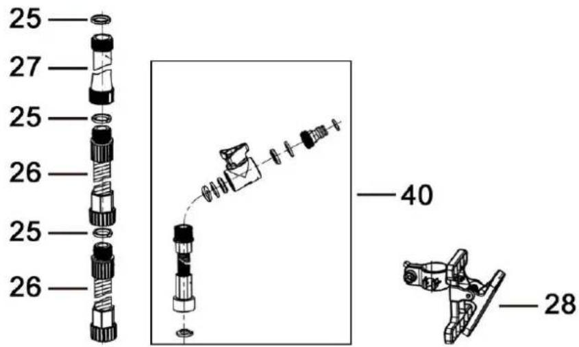
| Part-No. | Spare part No.. | Part description |
| 25 | 71625 | Seal |
| 26 | 70261 | Flexible pipe segment |
| 27 | 71626 | Rigid pipe segment |
| 28 | 70262 | Attachment clamp |
| 40 | 70263 | Outlet element |

11. Service
In the case of warranty claims or malfunction, please contact your point of sale.
A current operating manual is available as required as a PDF file via e-mail: service@tip-pumpen.de.
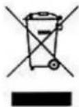
For EC countries only
Please do not dispose of electrical appliances in the regular domestic waste!
According to the European Directive 2012/19/EU regarding waste electrical and electronic equipment and the implementation of that directive into national law, electrical devices have to be collected separately and disposed off in an environmental-suitable manner after the end of their life cycle. Should you have any questions, please contact your local waste disposal company.
Chere cliente, cher client.
Functional parts / Details
1 Pressure port
7 Mains connection cable
13 Holder for float switch
2 Floating switch
8 Pump foot
3 Cable of floating switch
9 Pump foot screws
A Min. self-priming level *
4 Attachment clamp
10 Outlet element
B Min. suction level *
5 Carrying handle
11 dirt protective grid
C Cut-in level
6 Intake openings
12 Srews / distance holder
D Cut-out level
- The applicable values are specified in the "Technical details" section
F
Email: service@tip-pumpen.de