ELVOX ESM2.120 - Controller Vimar - Free user manual and instructions
Find the device manual for free ELVOX ESM2.120 Vimar in PDF.
User questions about ELVOX ESM2.120 Vimar
0 question about this device. Answer the ones you know or ask your own.
Ask a new question about this device
Download the instructions for your Controller in PDF format for free! Find your manual ELVOX ESM2.120 - Vimar and take your electronic device back in hand. On this page are published all the documents necessary for the use of your device. ELVOX ESM2.120 by Vimar.
USER MANUAL ELVOX ESM2.120 Vimar
1 - Product features 9
2 - System type 9
3 - Dimensions and overall dimensions 10
4 - Preliminary procedures 10
5 - Anchoring the gear motor. 11
6 - Operator height adjustment and fixing 11
- - Mounting the rack. 12
8 - Mounting the limit switch brackets 13
9 - Connecting to the power mains 14
10 - Electrical connections to the control panel. 14
ESM2, ESM2.120, ESM2.D, ESM2.D.120, ESM2.W, ESM2.W.120, ESM2.1000.W, ESM2.1000.W120
1 - Product features
ACTO 600D automatic gate system for heavy-use residential and condominium sliding gates. The non-reversible, electromechanical actuator is equipped with a low-voltage 24 Vdc motor and a mechanical release which enables the gate to be opened and closed manually. The motor operates a gear unit, lubricated with permanent grease, which is enclosed in a thick but extremely compact die-cast aluminium housing. The electronic control board is integrated in the body of the actuator, with the provision of a housing for the back-up battery (optional).
Technical characteristics
| Supply voltage | ESM2 230 Vac (+10%, -10%) ESM2.120 120 Vac (+10%, -10%) | ESM2.1000 230 Vac (+10%, -10%) ESM2.1000 120 Vac (+10%, -10%) |
| Frequency 50-60 Hz | ||
| Board voltage supply 22 Vac | ||
| Motor voltage supply 24 Vdc | ||
| Frequency of use Heavy duty service | ||
| Rated motor power 140 W 160 W | ||
| Speed 10 m/min 9 m/min | ||
| Rack Module 4 | ||
| Operating temperature From -25°C to +55°C | ||
| Protection rating IP45 | ||
| Noise < 70dBA | ||
| Maximum gate weight | 600 Kg | 1000 kg |
| Dimensions (WxHxD) | 308x270x225 mm | |
| Motor weight | 10.8 kg | |
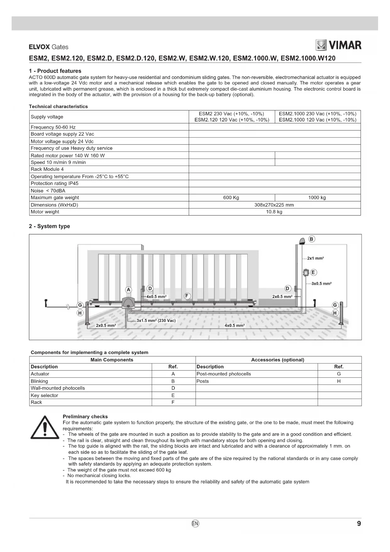
2 - System type
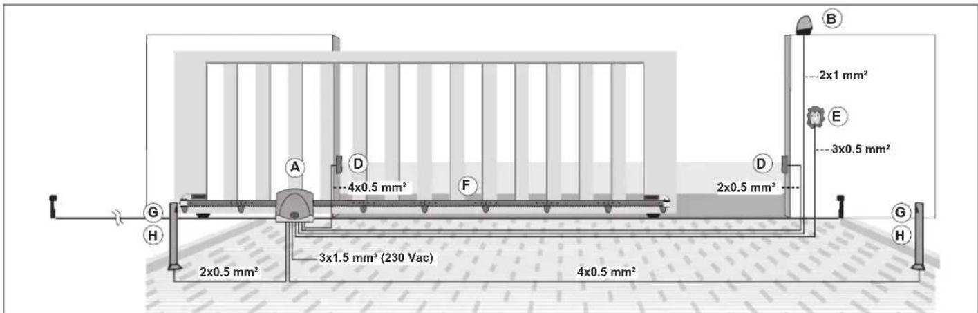
Components for implementing a complete system
| Main Components | Accessories (optional) | ||
| Description | Ref. | Description | Ref. |
| Actuator | A | Post-mounted photocells | G |
| Blinking | B | Posts | H |
| Wall-mounted photocells | D | ||
| Key selector | E | ||
| Rack | F | ||

Preliminary checks
For the automatic gate system to function properly, the structure of the existing gate, or the one to be made, must meet the following requirements:
The wheels of the gate are mounted in such a position as to provide stability to the gate and are in a good condition and efficient.
- The rail is clear, straight and clean throughout its length with mandatory stops for both opening and closing.
- The top guide is aligned with the rail, the sliding blocks are intact and lubricated and with a clearance of approximately 1 mm. on each side so as to facilitate the sliding of the gate leaf.
- The spaces between the moving and fixed parts of the gate are of the size required by the national standards or in any case comply with safety standards by applying an adequate protection system.
- The weight of the gate must not exceed 600kg
- No mechanical closing locks.
It is recommended to take the necessary steps to ensure the reliability and safety of the automatic gate system
ESM2, ESM2.120, ESM2.D, ESM2.D.120, ESM2.W, ESM2.W.120, ESM2.1000.W, ESM2.1000.W120
3 - Dimensions and overall dimensions
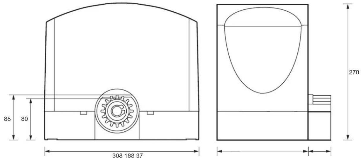
Fig. 1
4 - Preliminary procedures
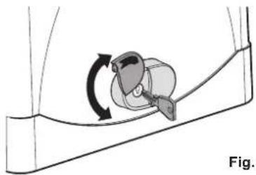
Fig. 2.1
Open the release flap, insert and turn the release key
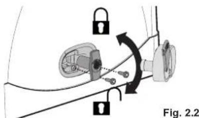
Fig. 2.2
Remove the release cover, loosen the screw on the release knob, remove the release knob and loosen the fixing screw on the cover on the gear motor casting
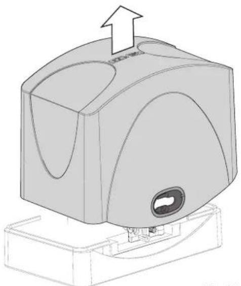
Fig. 2.3
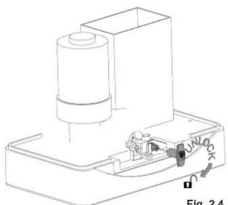
Fig. 2.4
Remove the cover from the gear motor
Reposition the release knob and release the gear motor by turning the knob clockwise 5 revolutions
Before securing the actuator, check the distance between the gate and the gear motor (see figure 3).
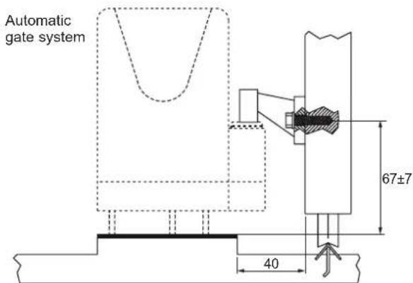
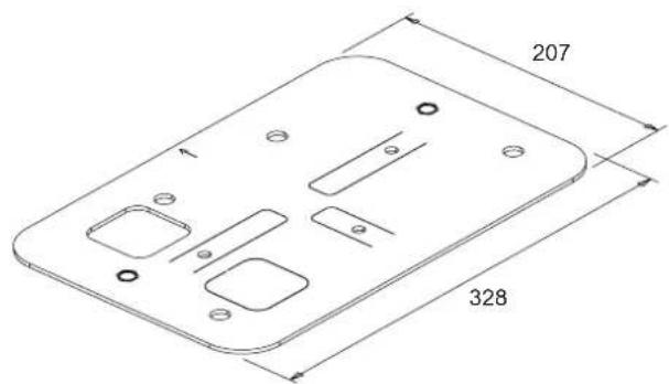
Fig. 3
ESM2, ESM2.120, ESM2.D, ESM2.D.120, ESM2.W, ESM2.W.120, ESM2.1000.W, ESM2.1000.W120
5 - Anchoring the gear motor
After identifying the position where you are going to install the gear motor (which can be to the right or left of the gate), you can anchor the gear motor to the ground in two ways:
A) by bedding the base plate into a concrete plinth (to be constructed)
B) by anchoring the plate to a concrete plinth (pre-existing or to be constructed) using 4 high-strength M10 metal anchor bolts (not supplied)
Note: the plate must be bedded in concrete or anchored taking care to respect the measurements given in Fig. 3 to ensure that the pinion meshes correctly with the rack.
We recommend that the plate is always bedded into a plinth that has a height of a few centimetres above ground level to avoid the risk of water collecting around the gear motor.
A) Bedding the plate in concrete
1) Screw the M8x50 screws (ref. A) fully into the threaded inserts (ref. B) in the plate (Fig. 4A).
2) Fit the rubber plugs (ref. A) on to the screws M8x50 (ref. B) screwed into the plate (Fig. 4B). These plug are essential as they prevent the cement adhering to the screws, so that, if necessary, the screws may be removed in the future.
3) Using a screwdriver, lift up the anchor tabs (Fig. 4C).
4) Position the plate so that the arrow (ref. A) is pointing towards the rack (Fig. 4D).
5) Insert the corrugated pipes for cables in the square hole (ref. B); the hole can accept one 32mm pipe and one 25mm pipe. If additional corrugated pipes are to be installed, open up the second square hole (ref. C) in the plate (Fig. 4D). The corrugated pipes must project 5cm beyond the plate.
6) Cast the concrete, making sure that the plate is positioned perfectly level.
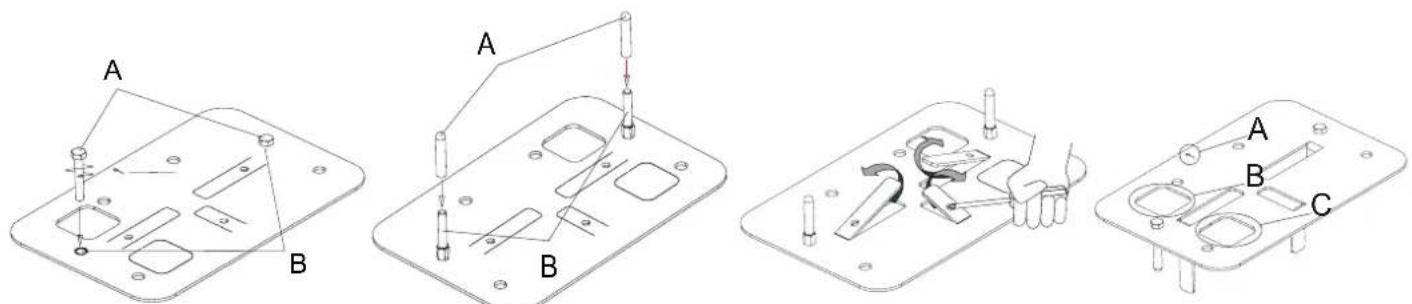
Fig. 4A Fig. 4B
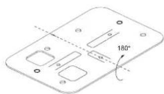
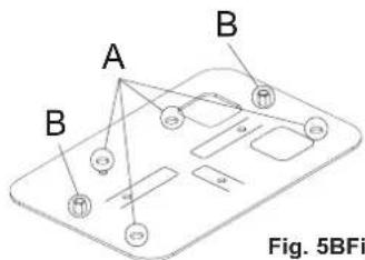
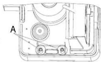
Fig. 5BFig. 5A
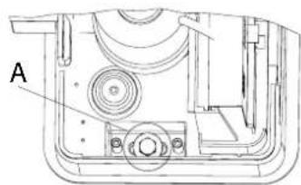
Fig. 6B
B) Anchoring the plate with expansion bolts
If there is no pre-existing plinth, construct a perfectly level and sturdy concrete plinth with an area sufficiently larger than the plate.
1) If a plinth is to be constructed, cast the concrete making sure that the corrugated pipes are positioned so as to allow the plate to be subsequently positioned correctly relative to the gate, as indicated in Fig. 3.
2) Turn the plate over through 180^ , keeping the arrow pointing towards the rack (Fig. 5A), and position it in accordance with the measurements in Fig. 3 and use it as a template to mark out the positions of the 4 holes for the anchor bolts (ref. A) and the gear motor fixing screws (ref. B) (Fig 5B). The plate must be turned over otherwise the threaded inserts would prevent it from lying flat.
3) Mark the centres of the anchors and of the screws and drill holes for the high-strength M10x120 anchor bolts (not supplied) and the holes for the gear motor fixing screws (at least 014 with min. depth 60 mm).
4) Reposition the plate and secure it to the concrete plinth.
6 - Operator height adjustment and fixing
The operator has a height adjustment mechanism to facilitate the adjustment of the clearance between the rack and pinion and to compensate any lowering of the track without having to adjust the rack.
To adjust the height and fix the gear motor, proceed as follows:
- If the M8x50 gear motor fixing screws are still screwed into the plate, unscrew them.
The gear motor base is fitted with 4 captive nuts positioned on the underside of the gear motor casting, alongside the fixing slots. Screw the 4 studs provided into the nuts through the holes (ref. A Fig. 6A).
Position the gear motor observing the measurements shown in Fig. 3. Rest the gear motor on the plate in its working position, fit the washers to the M8x50 fixing screws (ref. A Fig. 6B) and screw them in by just a few turns without tightening. - Screw in the studs to position the gear motor at the correct height and to ensure the correct clearance between the pinion and the rack; use a spirit level to check that the gear motor is level.
- Once the gear motor is positioned correctly, tighten the fixing screws.
ESM2, ESM2.120, ESM2.D, ESM2.D.120, ESM2.W, ESM2.W.120, ESM2.1000.W, ESM2.1000.W120
7 - Mounting the rack
Before you start installing the rack, check the mechanical stops of the gate. If they are missing or not strong enough you need to install them.
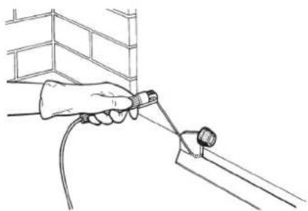
Fig. 7
If you are using the screw rack it is advisable to assemble the modules to verify that the fixing points do interfere with the movement of the wheels (see Figure 8).
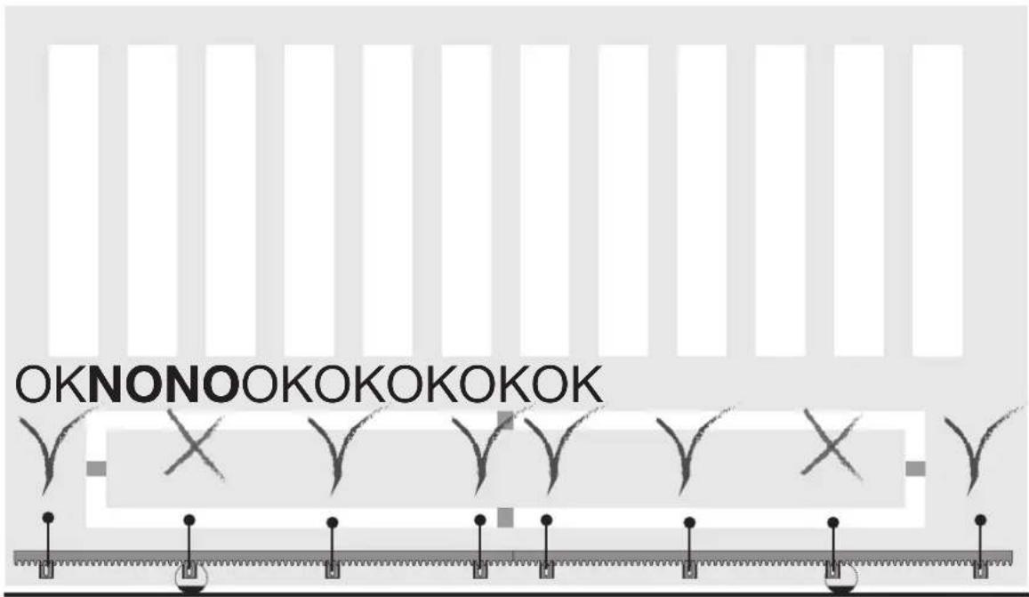
Fig. 8
There should be a clearance of 1.5mm between the pinion and rack over the whole length of the gate (Fig. 9). To adjust the clearance between the pinion and the rack, refer to paragraph "6 - Operator height adjustment and fixing".
N.B.: This operation is very important for the operation and durability of the gear motor. The load of the gate should not weigh on the pinion because it may damage the automatic gate system.
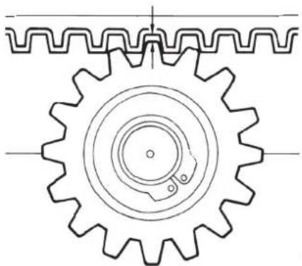
1.5 mm obtained at the end of the adjustment
Fig. 9
- After unlocking the actuator close the gate completely.
Rest the rack against the pinion of the gear motor. Before doing the drilling for fixing, check that the screws do not interfere with the movement of the wheels.
ESM2, ESM2.120, ESM2.D, ESM2.D.120, ESM2.W, ESM2.W.120, ESM2.1000.W, ESM2.1000.W120
Start securing the first metre of rack, moving the gate manually towards the opening, checking that it rests properly with the pinion of the actuator. Move the second element of the rack near to the previous one, using a piece of rack to align the teeth of the 2 elements correctly (see figure 10).
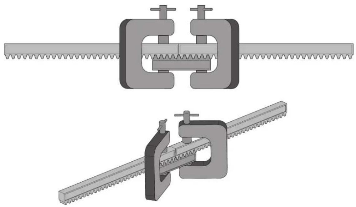
Fig. 10
Use the screws to secure the second element of the rack and repeat the procedure all along the gate.
8 - Mounting the limit switch brackets
Manually unlock the gear motor, move the gate to the point where it is completely open, secure the bracket of the limit switch Sx so that the magnet matches the sensor, move the gate to the point where it is completely closed, and secure the bracket of the limit switch Dx so that the magnet matches the sensor (see Figures 11-13).
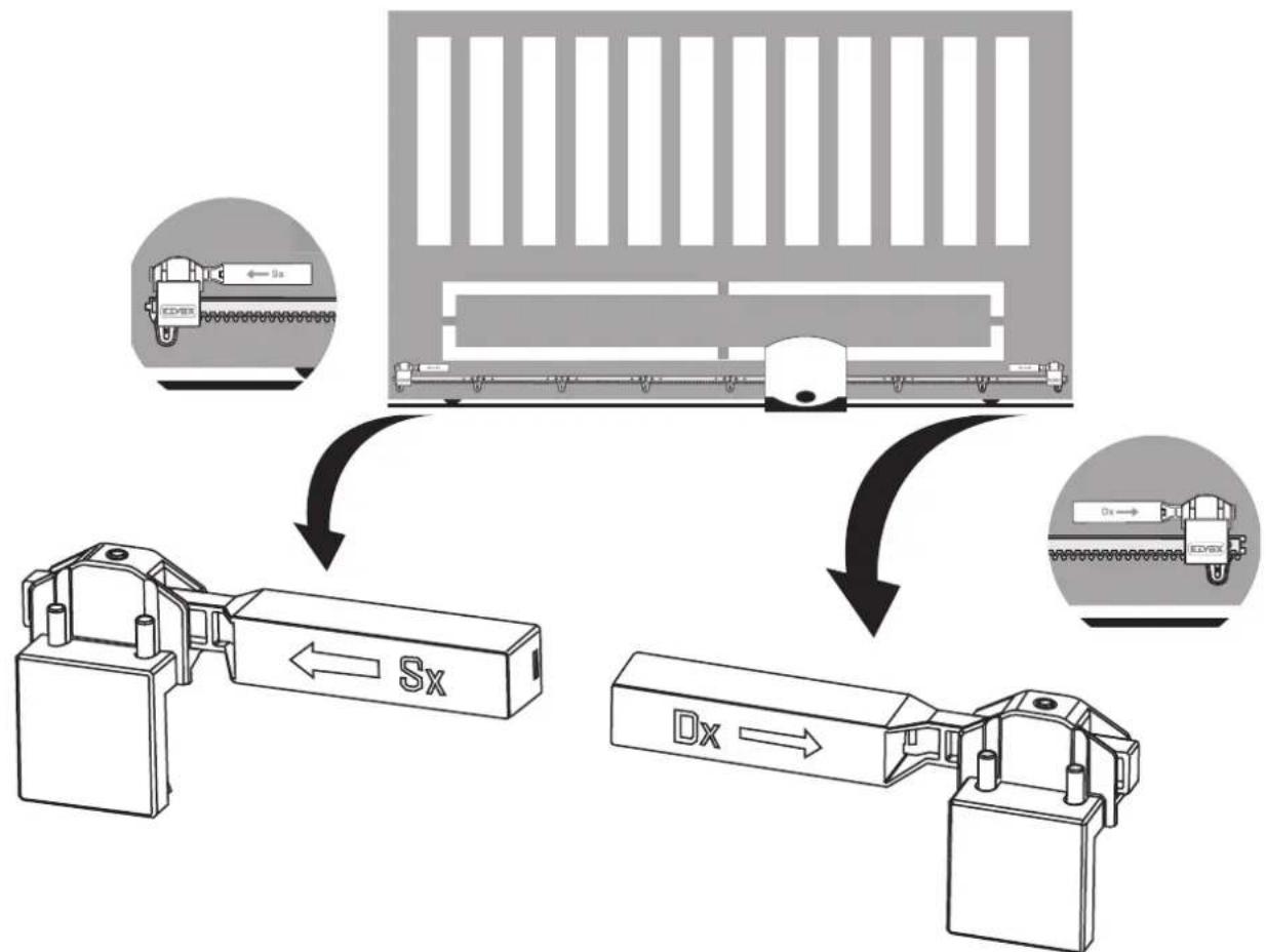
Fig. 11
ESM2, ESM2.120, ESM2.D, ESM2.D.120, ESM2.W, ESM2.W.120, ESM2.1000.W, ESM2.1000.W120
9 - Connecting to the power mains
Loosen the four screws (A) and remove the cover from the transformer seat.
Drill the cable outlet (B) situated in the gear motor base and thread the three-pole power supply cable through, stripping the phase and neutral for approximately 30 cm and the earth for approximately 5 cm. Fix the cable sheath by tightening the tear-proof clamp (C).
Phase and neutral must be connected to the fuse carrier situated inside the transformer housing (please refer to the control panel instructions), earth must be crimped to the eyelet (D) screwed onto the base of the gear motor.
Please refer to the detail in fig. 12.2 for the cable passage.
Reposition the cover onto the transformer seat and tighten all screws.
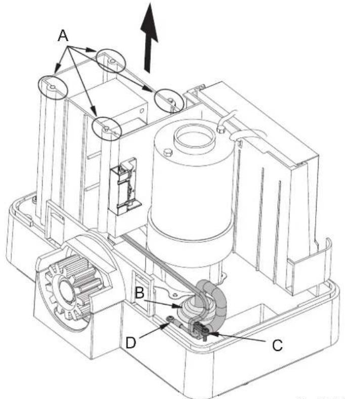
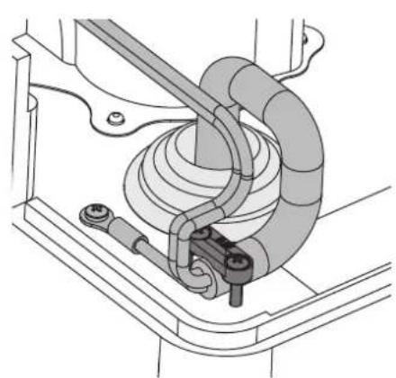
Fig. 12.1 Fig. 12.2
Once the electrical connections have been made, block the gear motor again and reposition the gear motor cover following the procedure illustrated in paragraph "4 - Preliminary procedures" in the reverse order.
10 - Electrical connections to the control panel
Below are the electrical connections to the control panel if replacement is necessary.
Reposition the cover onto the transformer seat and tighten all screws.
RS05/RS06
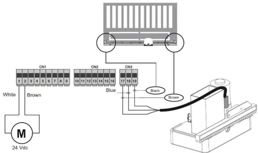
Fig. 13.1
ESM2, ESM2.120, ESM2.D, ESM2.D.120, ESM2.W, ESM2.W.120, ESM2.1000.W, ESM2.1000.W120
SL24.W
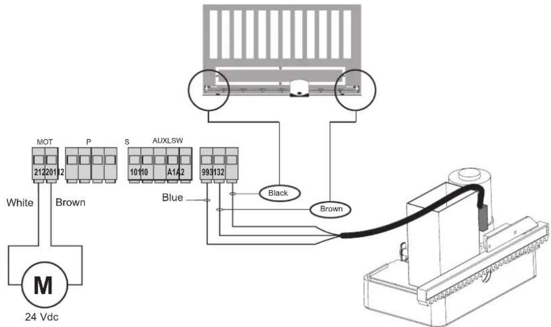
Fig. 13.2
SL24.T
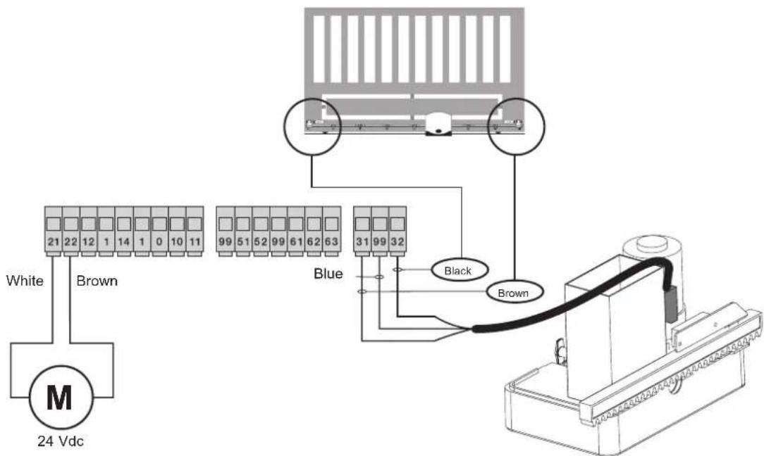
Fig. 13.3