
16470.B - Switch Vimar - Free user manual and instructions
Find the device manual for free 16470.B Vimar in PDF.

| Product Type | Transponder Key Reader (Switch) |
| Brand | Vimar |
| Model | 16470.B |
| Series | Idea |
| Rated Supply Voltage | BUS 20-32 V d.c. |
| Typical Consumption | 22 mA |
| RF Transmission Power | < 66 dBμA/m |
| Protection Class | IP30 |
| Operating Temperature | -5°C to +45°C |
| Installation | Flush or surface mounting |
| Interface | TP1 bus |
| Key Management | Up to 50 SLAVE keys, 4 MASTER keys |
| Relay Command | Monostable, activation time adjustable 0.25-10 s |
| Antitamper | Not active (for integration with Vimar alarm system) |
| Dimensions (approx.) | Standard flush-mount switch size (e.g., 80x80x40 mm) |
| Weight (approx.) | 150 g |
| Power Supply Requirement | BUS system powered by Vimar power supply (e.g., 01400) |
| Maintenance | Clean with a dry, soft cloth. Do not use solvents or abrasives. |
| Regulatory Compliance | RED Directive, EN 60669-2-5, EN 50491, EN 301 489-3, EN 300 330, EN 62311 |
| Disposal | WEEE compliant; do not dispose with household waste |
Frequently Asked Questions - 16470.B Vimar
User questions about 16470.B Vimar
0 question about this device. Answer the ones you know or ask your own.
Ask a new question about this device
Download the instructions for your Switch in PDF format for free! Find your manual 16470.B - Vimar and take your electronic device back in hand. On this page are published all the documents necessary for the use of your device. 16470.B by Vimar.
USER MANUAL 16470.B Vimar
Access control and appliance management via BUS
using a transponder card or key
HOME AUTOMATION

VIMAR
CONTENTS
- Legend 2
- Installing the system via BUS 3
- Main features and functions of the system components.... 5
3.1 - Transponder key reader.... 5
3.2 - Transponder card and key 6
3.3 - Relay actuator 8
3.4 - Power supply unit.... 9
- Operation 10
4.1 - Initializing the transponder reader and coding keys.... 10
4.2 - Activating configuration status.... 12
4.3 - Pairing with the relay.... 14
4.4 - Coding SLAVE keys.... 16
4.5 - Deleting one or more SLAVE keys 18
4.6 - Deleting all the SLAVE keys 19
4.7 - Deleting the 4 MASTER keys.... 20
4.8 - Operation test 21
-
Installation rules 22
-
Regulatory compliance 22

VIMAR
1. Legend

Operations to be performed solely by skilled personnel

Operations that can be performed also by the user
LED off

LED on green

LED on red

LED on amber

LED blinking green
amber
LED blinking amber
red
LED blinking red
red
LED blinking red-off-green
green


red
LED blinking red-green
green

red
LED blinking red-amber
amber

2. Installing the system via BUS
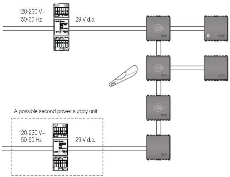
- For the connections use the twisted pair and sheathed cable VIMAR 01840.E (2 x 0.5 mm ^3 ). The wire pair distributes both the power supply voltage (29 V d.c.) and the device control signals.
- The devices do not have to be connected in any particular order, maintaining the polarities indicated on the terminals.
- The voltage at each point of the bus must never fall below 20 V. In particular, check the points farthest from the power supply unit and the sections of cable where the load is greater.
- The total current used by the various devices must not exceed the nominal current of the power supply unit. Make sure that the current drawn by a device increases as the power supply voltage decreases (for the consumption of the device, please refer to its instructions booklet).
- A bus system must be supplied by 1 or 2 power supply units and related chokes (diagram on page 4).
• Maximum bus cable length with 1 power supply unit: 250 m.
- Maximum bus cable length with 2 power supply units: 500 m. For optimum load distribution, it is necessary to connect the two power supply units to the two ends of the bus.
- For "star" bus connections, avoid creating branches of the bus that are too long and have few devices; it is recommended not to exceed lengths of 50m if the branch has no more than one device and 100m if there are no more than 5 devices. The best case is when the branches have devices distributed along the cable.

VIMAR
flowchart
graph TD
    A["120-230 V~50-60 Hz"] -->|29 V d.c.| B["Device 1"]
    C["120-230 V~50-60 Hz"] -->|29 V d.c.| D["Device 2"]
    B --> E["Device 3"]
    D --> F["Device 4"]
    style A fill:#f9f,stroke:#333
    style C fill:#f9f,stroke:#333
    style B fill:#ccf,stroke:#333
    style D fill:#ccf,stroke:#333
    style E fill:#dfd,stroke:#333
    style F fill:#dfd,stroke:#333

VIMAR
3. Main features and functions of the system components
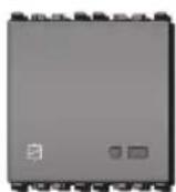
3.1 - Transponder key reader
Technical characteristics:
- Rated supply voltage (Vn): BUS 20-32 V d.c.
• RF transmission power: < 66 dBμA/m
• Protection class: IP30 - TP1 bus interface
• Transponder reader
• Typical consumption: 22 mA - Operating temperature: -5^ - +45^ .
Eikon
20470
Idea

16470
Plana

14470
Main functions:
- Local key management, with programming procedure, via one or more enabling keys.
- Priority key management; up to 50 SLAVE keys can be saved and 4 MASTER keys must be saved. With the enabling keys you can delete all the keys or a particular key (if available).
- Monostable relay command (the relay activation time is adjusted with a trimmer on the relay itself).
- Antitamper (not active). This feature can only be used when there is integration with the Vimar intrusion detection alarm system.
- Command for enlisting the relay (procedure that is activated when there is an enabling key and by pressing the button on the front).
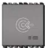
natural_image
Diagram of an electronic device with two ports and a cable, no text or symbols presentKey:
+, - : Connection to BUS
3.2 - Transponder card and key
Transponder keys and transponder cards offer absolute safety and reliability. Each key/each card contains a different code chosen from among more than 1000 billion possible combinations. The code's uniqueness is ensured by the key and card production process. They work without a battery, so they have unlimited, maintenance-free operation.

VIMAR

01815

01816 - 01816.H (front)

01816 (rear)

01816.H (rear)
Operation
The inductive coupling between the connector, which contains the primary winding of a transformer, and the transponder key or card, which contains the secondary winding (coil in a small capsule), generates energy that activates the secondary winding, which responds by modulating and transmitting the code. The code is transmitted by setting the transponder key or card into contact (as shown by the posi-
tion of the arrow - figures 3.2a and 3.2b for the key; figures 3.2c and 3.2d for the card) with the connector, which is recognized and signalled to the system. The keys and cards can have a MASTER or SLAVE function. The MASTER function enables opening the enabled accesses and performing reader management and maintenance operations. The SLAVES permit opening the enabled accesses only. The following illustrations show the transponder key. Its operation is identical to that of the transponder cards.


VIMAR


VIMAR
3.3 - Relay actuator
The actuator is a device that, thanks to the potential-free contacts of the relay with which it is provided, is able to control electric locks, activate the lighting circuit, etc.
Technical characteristics
- Rated supply voltage (Vn): BUS 20-32 V d.c.
- Protection class: IP30
- Operating temperature: -5 to +45^ (for indoor use)
• Installation: flush or surface mounting
• Rated relay data: 3 A 30 V
• Average consumption: 8 mA
• Monostable mode operation - Trimmer for adjusting activation time from 0.25 to 10 s
- Configuration push-button
Eikon
20472
Idea
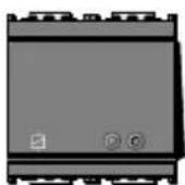
16472
Plana

14472
- Indicator LED:
- LED on red: in configuration phase
- LED on green: relay activated
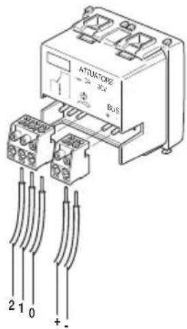
Key:
+, - : Connection to BUS
0: Common
1: Contact normally open
2: Contact normally closed

VIMAR
3.4 - Power supply unit
The power supply unit enables obtaining a voltage of 29 V d.c. for powering the system via BUS.
01400: Power unit with decoupling coil. At most 2 power units can be installed on each line.
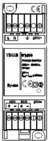
01400
Technical characteristics
• Power: 230 V\~ 50/60 Hz
• Consumption: 150 mA
• Dissipated power: 4 W
- BUS output voltage: 29 V d.c. (SELV) with decoupling coil
• AUX output voltage: 29 V d.c. (SELV)
• Total max output current: 400 mA (IBUS + IAUX)
- Two-colour LED green/red
- Operating temperature: -5^ - +45^ (from inside)
- 2 modules size 17.5 mm; installation on consumer units with DIN rails (60715 TH35)
• Class II symbol

VIMAR


4. Operation
To make the system for access control via bus with transponder keys operative, you must perform the following tasks in sequence:
- save the 4 MASTER keys;
- enlist the relay;
- save the SLAVE keys.
Note:
The MASTER key is the enabling key for all the functions.

4.1 Initializing the transponder reader and coding keys
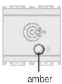
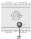
If the device is not paired with a MASTER key (in other words it has never been used), on starting it remains blocked, waiting to read 4 keys (the status is indicated by the LED on amber).
4.1.1
Power up the reader.
4.1.2
If the reader has never used the LED will light up amber.
4.1.3
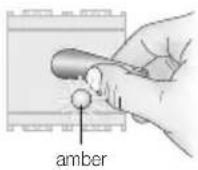
Place the transponder key on the reader. Key saving is indicated by the LED blinking amber, then it goes back to steady amber.
4.1.4
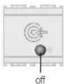
Repeat this operation with another 3 keys. After reading the 4 keys the LED will go out (Fig. 4.1.5).
You need to have each reader read 4 keys; the same key can also be used 4 times.
For convenience, it is advisable to use the same MASTER keys for all the readers installed.

VIMAR
4.1.5
After saving the 4 MASTER keys, the reader is ready for configuration and operation:
- pairing with the relay
- adding SLAVE keys
- deleting one or more SLAVE keys
- deleting all the SLAVE keys
• recoding the MASTER keys

VIMAR

4.2 Activating configuration status
Use this procedure to set the transponder reader in configuration status, in order to then be able to program the various functions.
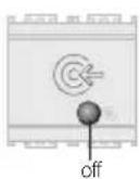
4.2.2
Press the button again. The LED turns green.

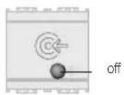
4.2.1
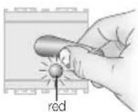
Press the button. The LED blinks red-off-green in an intermittent sequence.
4.2.3
Move the MASTER key near within 15 seconds. If the key is recognized, the LED will blink green 2 times and then go out.
If the LED blinks red the MASTER key has not been recognized. Repeat the operation with the correct key.
If no operations are carried within 30 seconds the reader will go back into its normal state. Resume the operations from point 4.2.1

30"

VIMAR

4.2.4
Depending on the mode and the colour of the LED that is on, obtained by repeatedly pressing the button, you activate the following functions:
• LED on red: pairing with the relay
• LED on green: adding SLAVE keys
- green LED blinking: deleting SLAVE keys
• red LED blinking:
deleting all the SLAVE keys
- amber LED blinking: no function
• LED alternating green-red: deleting the 4 MASTER keys

4.3 Pairing with the relay
Use this procedure to pair a relay with the transponder reader. The paired relay will then be activated only if the transponder reader recognizes the key.
4.3.1
The reader must be in configuration status (the sequence of operations described in Chapter 4.2 must have been carried out).
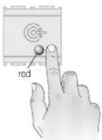
4.3.2
Press the button until the LED lights up red.

VIMAR
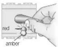
4.3.3
Bring the MASTER key near to the transponder reader. The LED blinks alternately red-amber.
If the LED blinks red the key has not been recognized. Repeat the operation with the correct key.

4.3.4
Press the button of the relay for pairing (the relay is distinguished by the actuator symbol shown in the figure).
The relay's LED will illuminate red and stay on until configuration has completed and then turn off.

Note: During configuration, the transponder reader LED will keep on blinking red-amber alternately and then go out upon completing configuration.
4.3.6
After pairing the relay, the transponder reader LED switches off and the device exits configuration status.

VIMAR
4.3.7
If necessary adjust the monostable relay activation time from 0.25 to 10 seconds, by using the trimmer.


VIMAR

4.4 Coding SLAVE keys
Use this procedure to code SLAVE keys, which will be recognized only by the transponder readers that have coded them.

4.4.3
Bring the reader near to the key to be coded as a SLAVE. The LED will blink 2 times to signal coding has completed and then go back to green.
4.4.1
The reader must be in configuration status (the sequence of operations described in Chapter 4.2 must have been carried out).
4.4.4
Repeat this step for the other SLAVE keys to code; each time the LED will blink to signal successful coding

4.4.2
Press the button a number of times until the LED lights up green.
4.4.5
The same key can be coded also on other readers by repeating the previous step.

VIMAR
4.4.6
To exit the procedure, press the button repeatedly until the LED switches off.

4.5 Deleting one or more SLAVE keys
Use this procedure to delete any SLAVE keys that are brought near to the transponder readers. MASTER keys cannot be deleted with this procedure.
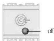
off
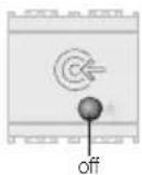
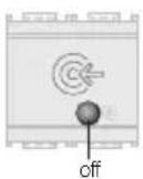
If no operations are carried within 30 seconds the reader will go back into its normal state.
4.5.1
The reader must be in configuration status (the sequence of operations described in Chapter 4.2 must have been carried out).

30"

VIMAR

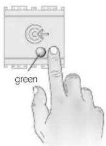
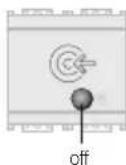
4.5.2
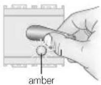
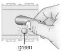
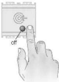
Press the button a number of times until the LED is blinking green.
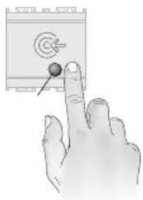
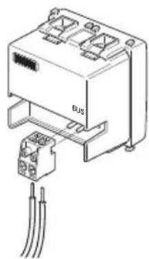
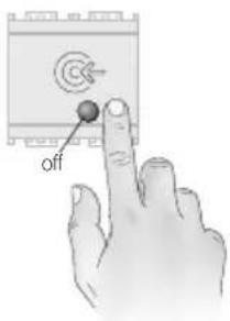
natural_image
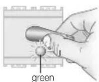
Hand pointing at a device with a target symbol and arrow (no text or labels)4.5.4
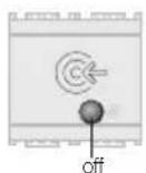
To exit the procedure, press the button repeatedly until the LED switches off.
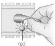
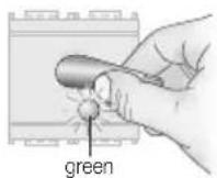
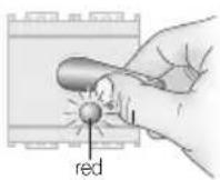
4.5.3
Bring the SLAVE key near to the reader. When the LED blinks red, the key has been deleted.
Repeat this step for the SLAVE keys that you want to delete.

off

30"
If no operations are carried within 30 seconds the reader will go back into its normal state.

VIMAR

4.6 Deleting all the SLAVE keys
Use this procedure to delete all the SLAVE keys by bringing a MASTER key near to a transponder reader.
4.6.1
The reader must be in configuration status (the sequence of operations described in Chapter 4.2 must have been carried out).
4.6.2
Press the button a number of times until the LED is blinking red.

4.6.3
Bring a MASTER key near to the reader. When the LED blinks green, all the SLAVE keys are deleted.
4.6.4
To exit the procedure, press the button repeatedly until the LED switches off.

off

30"
If no operations are carried within 30 seconds the reader will go back into its normal state.

VIMAR

4.7 Deleting the 4 MASTER keys
Use this procedure to delete the 4 MASTER keys by bringing one near to the transponder reader. After deletion, the reader sets up to recode the MASTER keys.

4.7.2
Press the button a number of times until the LED lights up alternating red-green.

4.7.1
The reader must be in configuration status (the sequence of operations described in Chapter 4.2 must have been carried out).
4.7.3
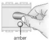
Bring a MASTER key near to the reader. When the LED turns amber, all 4 MASTER keys are deleted. The reader remains blocked with the amber LED on, waiting to code 4 keys again.
4.7.4
Initialize the system by performing the procedures of paragraph 4.1

VIMAR

4.8 Operation test
Use this procedure to check the system works properly.
4.7.3
Bring a MASTER key or a SLAVE key near to the reader.
If the key is recognized, the transponder reader LED will blink green 2/3 times, and the relay LED will light up green for the activation time on which it is set.

5. Installation rules
Installation should be carried out by qualified staff in compliance with the current regulations regarding the installation of electrical equipment in the country where the products are installed.
6. Regulatory compliance
RED directive.
Standards EN 60669-2-5, EN 50491, EN 301 489-3, EN 300 330, EN 62311.
Vimar SpA declares that the radio equipment complies with Directive 2014/53/EU. The full text of the EU declaration of conformity is on the product sheet available at the following Internet address: www.vimar.com.

VIMAR
WEEE - Information for users
If the crossed-out bin symbol appears on the equipment or packaging, this means the product must not be included with other general waste at the end of its working life. The user must take the worn product to a sorted waste center, or return it to the retailer when purchasing a new one. Products for disposal can be consigned free of charge (without any new purchase obligation) to retailers with a sales area of at least 400 m², if they measure less than 25 cm. An efficient sorted waste collection for the environmentally friendly disposal of the used device, or its subsequent recycling, helps avoid the potential negative effects on the environment and people's health, and encourages the re-use and/or recycling of the construction materials.

20470 EN 03 1810

VIMAR
Viale Vicenza, 14
36063 Marostica VI - Italy
www.vimar.com


- VIMAR
- CONTENTS
- Legend
- Installing the system via BUS
- Main features and functions of the system components
- - Transponder key reader
- Technical characteristics:
- Main functions:
- - Transponder card and key
- Operation
- - Relay actuator
- Technical characteristics
- Key:
- - Power supply unit
- Operation
- Note:
- Initializing the transponder reader and coding keys
- 4.1.1
- 4.1.2
- 4.1.3
- 4.1.4
- 4.1.5
- Activating configuration status
- 4.2.2
- 4.2.1
- 4.2.3
- 4.2.4
- Pairing with the relay
- 4.3.1
- 4.3.2
- 4.3.3
- 4.3.4
- 4.3.6
- 4.3.7
- Coding SLAVE keys
- 4.4.3
- 4.4.1
- 4.4.4
- 4.4.2
- 4.4.5
- 4.4.6
- Deleting one or more SLAVE keys
- 4.5.1
- 4.5.2
- 4.5.4
- 4.5.3
- Deleting all the SLAVE keys
- 4.6.1
- 4.6.2
- 4.6.3
- 4.6.4
- Deleting the 4 MASTER keys
- 4.7.2
- 4.7.1
- 4.7.3
- 4.7.4
- Operation test
- Installation rules
- Regulatory compliance
- WEEE - Information for users
Brand : Vimar
Model : 16470.B
Category : Switch