
ELVOX 945B - Switch Vimar - Free user manual and instructions
Find the device manual for free ELVOX 945B Vimar in PDF.


| Product Type | Porter's Switchboard (desk-top version) |
| Brand | Vimar |
| Model | ELVOX 945B |
| Housing Material | Black thermoplastic |
| Display | LCD, 40 characters x 2 lines, with icons |
| Keypad | 20 keys, divided into two sections |
| Power Supply Voltage | 13.5 Vdc (terminal 10 positive, 9 negative) |
| Power Consumption | Not specified; typical < 10 W |
| User Capacity | Up to 99,999,999 users |
| Call Memory | 30 events (circular queue) |
| Wake-up Services | 2 programmable daily alarms |
| Clock Backup | Capacitor backup (~4 days) |
| Intercom / Conference | Supports up to 3 parties |
| Door Lock Release | Via terminal S and software key |
| Additional Functions | F1, F2, F6, F7, F8 (auxiliary relays optional) |
| Printer Interface | Optional (Art. 945B/I), parallel port |
| Melody Customization | 5 preset melodies; downloadable via PC/interface |
| PC Connectivity | Via serial interface for data download/config |
| Operating Temperature | 0°C to 40°C (estimated) |
| Dimensions (approx.) | 200 x 150 x 80 mm (desk-top) |
| Weight (approx.) | 1 kg |
| Maintenance | Clean with a dry cloth; avoid liquids and abrasives |
| Safety Compliance | EMC directive; standards EN 60065, EN 61000-6-1, EN 61000-6-3 |
| Spare Parts / Repairability | Contact Vimar authorized service; internal circuit board programmable |
Frequently Asked Questions - ELVOX 945B Vimar
User questions about ELVOX 945B Vimar
0 question about this device. Answer the ones you know or ask your own.
Ask a new question about this device
Download the instructions for your Switch in PDF format for free! Find your manual ELVOX 945B - Vimar and take your electronic device back in hand. On this page are published all the documents necessary for the use of your device. ELVOX 945B by Vimar.
USER MANUAL ELVOX 945B Vimar
Porter's Switchboard
DESCRIPTION
Porter's switchboard in desk-top version with black thermoplastic housing. This switchboard can call up to 99999999 users using a 20-key keypad which serves to enter user numbers, make calls, activate intercom or conference functions (excluding the building complex), release the door lock and for F1-F2 functions and to cancel the operation currently in progress. The switchboard can store up to 30 different calls (displayed by using the memory scroll button) and is provided with watch (with time and date) and two wake up functions. Option to manage a printer (use switchboard Art. 945B/I with printer interface)
MANAGING THE DISPLAY (40X2):
The switchboard display is (in its typical operation state) divided in 5 main zones in order to allow an easy and immediate distinction of all data displayed.
UPPER LINE
3 zones may be distinguished:
Left hand side: display of all outgoing messages, and also particular information signalling.
Centre: display of the number to be dialled (8 digits) or the respective message on its left hand side
Right hand side: display of the current time.
LOWER LINE
- Left hand side: display of all incoming messages (from internal units or from external lines), followed by respective number.
- Right hand side: display of a series of "icons" able to show in a graphic way a wide series of states/functions.
"ICON" DESCRIPTION


+ (box with an arrow, followed by a number): It shows that there are calls (or other commands) in the memory (5 = er of queued calls)

(Telephone handset): It means the handset is lifted.

(Arrow toward the wire at the left hand side): It indicates intromission in the conversation line by the switchboard's operator.

(Key): It means there is a lock release or a function activation in progress.

(Bell in movement): It means there is a call in progress (ring). Is then being replaced by an "A" indicating a "Wait for the er" and then by a "C" indicating a "Conversation in progress" (NOTE: with hooked handset).


or (Telephone in movement): It means there is a connection with the telephone line.

(Lock): Indicates "locked keypad" by an external key.
(Int) (Ext): Indicates the switchboard state (Internal or External mode).

Exclusion of sound (by using R+3).

(Lock in movement): Indicates 'locked keypad'.
Moreover, the display switches its operation if there is any particular function.
QUICK GUIDE
- Parameter programming (R+4) + code
- Displaying the date-time-wake up (R+2), (or R+"8->8")
- Entering the code for keypad lock (R+1)
- Activation of accessory functions (KEY)
- Programming the events to store (R+)

- Programming the events to print (Press again the push-button)

- Setting the time for wake up service 1 (Press again the push-button)

- Setting the time for wake up service 2 (Press again the push-button)

- Setting the time (Press again the push-button)

- Setting the date (Press again the push-button)

- Exclusion - Reactivation of audio sound
R + 3
STORED CALLS
- Possibility of storing different types of "events": calls from interphones, activation of: different functions, door lock release, calls from switchboard. The selection of the type of events to store is managed by interactive menu type display (see "OPERATION OF MENU PROGRAMMING").
- Besides the type of message concerning the type of event and the calling number, the time of the event is stored.
- Maximum number of stored messages: 30 with circular queue (i.e. the latest 30 more recent events are stored).
- Storage of events on the watch backed up RAM (by means of a proper capacitor). In case of mains failure there is no loss of stored data.
- The events may be sent to a printer simultaneously (option with interface type 945B/I).

- In case of events stored in the memory, a special flashing icon is activated (arrow toward the box 📄) on the display and also the number of stored messages. As soon as a message is read it gets cancelled and the number decreases.
- A sound simultaneous with the event reception is generated (programmable).
INTERNAL WATCH WITH DATE AND TIME AND 2 WAKE UP SERVICES
It is always possible to display the present date and time. The internal watch is "backed up" (by means of a capacitor) in case of mains failure (capacitor supply dwell: nearly 4 days). Two wake up services may be also programmed.
AUDIO EVENTS
Different types of sounds are foreseen according to different type of events (call from riser, from external lines, wake up service etc.). The sounds may be also programmed with musical melodies by means of a special software and an interface connected to a personal computer.
"SOFTWARE" LOCK KEY
The switchboard keypad may be locked by means of the "software key".
SIMPLIFIED MANAGEMENT OF THE "INTERNAL-EXTERNAL" MODE PUSH-BUTTON.
Now the "Internal-External" push-button (I/E) has only the function to switch from the internal to the external mode. In this new version there is no keypad lock activation. At any time it is possible to recognize the switchboard state: a proper symbol on the bottom on the right hand side of display (icon zone) indicates the mode ("1" for internal mode and "E" for external mode). On external mode also the respective "EXTERNAL" mode LED switches on. NOTE: the state is memorized in EEPROM and is kept stored even during the mains failure.
MANAGING THE PRINTER
- The printer is connected by means a special optional interface, built-up inside the same switchboard.
- Any printer provided with connected parallel circuit board may be installed (not any more a dedicated printer). It is the internal software to manage the different models.
- A wide range of data may be selected (either on reception either on transmission).
CIRCUIT BOARD RE-PROGRAMMING "IN-CIRCUIT".
The circuit board may be easily programmed "in-circuit" by proper connector (above all useful for special versions).
POSSIBLE CONNECTION TOWARD A PC
By means of a computer equipped with a proper software and interface it is possible to download the data (events in memory), to manage the configuration parameters, to manage the names in memory (optional), and to set various functions. Moreover, it is possible to modify the musical melodies, the direct event recording, and to make a partial switchboard selfdiagnose.
PROGRAMMING THE SWITCHBOARD PARAMETERS
The switchboard is delivered with an "already inserted" basic program, which can be modified according to the instructions to follow. The programming is necessary if the pre-programmed parameters do not satisfy the installation requirements.
A) Entry to programming mode using the front switchboard keypad
Press push-buttons "R" and "4" simultaneously on the front keypad.
When a series of symbols "#######" is displayed on the screen, digit code "123". If the above sequence has been correctly performed "PROGRAM" will be displayed on the LCD screen. If this is not the case, repeat the entire procedure.
Once you have entered the programming mode use the bell button to scroll the following parameters and the numerical keys to modify the associated values. In the case of error, only use the numerical keys to correct the value entered. Press
push-button to confirm any changes. On completion of programming, press push-button and then R to exit the technical programming function.
Parameters may be programmed and consulted as and when required.
Parameter settings are stored in the memory even in the event of power failure until next edited.
Switchboard technical parameters table
Parameter Minimum value Maximum value Set value Description
| Initial user 1 99999999 00000001 only for building complex |
| Final user 1 99999999 99999999 only for building complex |
| System Number 1 99999999 00000000 It assigns a code to the switchboard |
| (for direct call from entrance panel or remote programming). | ||||
| 1 99999999 00000000 Not used | ||||
| Technical prg. key | 0 9999 00000123 Technical programming access code | |||
| Dis switch keypad | 0 9999 0000027 | Switchboard keypad disable code | ||
| * Number of digits | 4 | 8 | 000004 | 4/8 digit selection |
| Language | 0 | 1 | 000000 | 0 = Italian language1 = English language |
| Entr. Pan. Prefix | 0 | 99 | 000099 | The two digits indicate the call function from the external panel to the switchboard |
| Lock abilit | 0 | 1 | 00001 | Enables transit of door lock activation(0 = NO, 1 = YES) |
| Camera abilit | 0 | 1 | 00001 | Indicates presence of switchboard(0=NO, 1=YES). |
| Sound enable | 0 | 2 | 00002 | 0= Disable all chimes1= Enables the internal call chime2= Enables the external and internal call chime |
| Ring time enable | 0 | 1 | 00001 | Sound enabling for the clock signal |
| Function Vis. enable | 0 | 1 | 00001 | Function display enabling |
| Switchboard dialling code | 1 99 | 00000000 The two digits indicate the call function fromswitchboard and switchboard | ||
| Call rip. number | 1 | 255 | 00003 | Enables the switchboard call chime for the programmed intervals |
| Conversation time | 1 | 255 | 00012 | Maximum conversation time (time = value x 10 seconds; 12 = 120 seconds) |
| Ring duration | 1 | 255 | 00001 | Call signal activation time(time = value x 1 second) |
| Answer time | 1 | 255 | 00030 | Relay delay time(time = value x 1 second) |
| F1 time | 1 | 255 | 00001 | EM1 auxiliary function activation time(time = value x 1 second) |
| F2 time | 1 | 255 | 00001 | EM2 auxiliary function activation time(time = value x 1 second) |
| Lock time | 2 | 255 | 00001 | Door lock activation time(time = value x 1 second) |
| Printer Set | 0 255 | 00001 | Printer setup | |
| Enables call transit | 0 | 1 | 00000000 | Enables external call transit: YES - NO |
| Reserved parameter | 0 1 | 00000000 Reserved parameter | ||
press R to exit
Same parameter as that of the entrance panel and internal product programming (interphone-monitor).
OPERATION
DISPLAYING THE TIME - DATE - WAKE UP TIME-TABLE
The time is always displayed at the top on the right hand side of display.
To display other data press push-buttons R+2 (or R+Number transf. [8->8]), and the following message will appear:
DATE: 14/02 15:30:35
AL.RING: 12:30 & 18:30
ACTIVATION OF LOCK RELEASE, F1, F2 AND OF THE ACCESSORIES FUNCTIONS F6, F7, F8:
Pressing the "CHIAVE" (Key) push-button the following menu will appear:
SELECT OPEN?
(0=LOCK; 1=F1; 2=F2; 6=F6; 7=F7; 8=F8).
Pressing a numerical push-button the respective command is activated. Besides the normal door lock ("O" push-button) it is possible to activate Function 1 (push-button 1) and F2 (push-button 2). The activation in this case works on proper pin and send downward the corresponding digibus command (to possible main entrance panels).
Pressing, on the contrary, the numerical push-buttons 6, 7 or 8 it is to send an auxiliary command (F6, F7 or F8) to a possible auxiliary relay (type 170D) in order to allow other possible external functions (stair light, irrigation etc.) to be activated (other 5 external functions (max) may be activated besides the door lock).
In all cases during the activation time the "key" icon is simultaneously activated.
SWITCHBOARD LOCK BY MEANS OF A SOFTWARE KEY
The complete keypad lock may be made by inserting a password. This password must be previously stored in the technical parameters (parameter = "CHIAVE BLOC SW.") with a number included between 1 and 32000.
To activate the lock using the software key, press push-buttons "R+1" simultaneously. A request for password appears:
Cod. Bloc. Tas. ?
Enter then the password and press C (default password=27)
The switchboard keypad is now blocked. The display shows the message "!BLOCCO CHIAVE!" (locked keypad). Transit and calls toward the switchboard are in any case completely active.
To release it repeat the same procedure repeating the same password.
To modify the password enter the parameter programming (pressing "R+4") and enter the parameter "Chiave Bloc. Sw." using the wanted password value.
NOTE: the lock operates even during a mains failure.
CONFIDENTIAL: If you forget the password enter the programming mode by using push-buttons on the lower side. Press PS2 and release it, press and keep pressed PS1 until the message PROGRAM appears and check the password in the analog parameter in the memory.
QUEUE OF STORED CALLS:
The backed-up memory keeps the latest 30 requests from internal units (calls and/or F1 and/or F2 and/or APERTURA_SERRATURA (lock release) according to the programming) complete with the reception time. In this case a special event counter with icon (box with arrow) signals the number of events in the memory on the display (and the proper led switches on).
Recording time
14:30
00000000
14:56:30
Chiam.citof.N 00123456 03
Type of command and number of the calling internal unit. the icon "
Counter for number of events memory (it is alternated with commandi in memoria"
(command in memory).
You can scroll the events by pressing push-button "MEM". Pressing push-button "trasferimento numero" (number transfer) (8->8) the number is got from the memory and displaced onto the call display, so as it can be called upon request. The event counter for consequence decreases the event number.
To blank the memory completely and automatically press push-button and keep it pressed for nearly 3 seconds. A short tone and the event counter cancellation will confirm the complete buffer blanking.
PROGRAMMING MENU
In the switchboard it is possible to program a series of accessory functions, such as:
- TIME AND DATE
- 2 WAKE-UP SERVICES
- THE TYPE OF COMMAND YOU WANT TO MEMORIZE IN THE RECEPTION BUFFER (AND SIGNAL IT WITH A MELODY)
- THE TYPE OF COMMAND YOU WANT TO SEND TO THE PRINTER (OPTIONAL).
There is a proper menu to enter these functions, which can be selected by pressing push-buttons R+ simultaneously (memory). The first selection function appears on display (COM. TO MEMO?). If it is the desired item you must digit the requi-
red value and then press C, or go to the next function by pressing push-button several times until reaching the required item. Find hereby the different functions (in the order as they appear):
1) PROGRAMMING THE COMMANDS TO BE STORED ("COM. TO MEMO" on display):
It allows to select the commands (received by the serial) to be memorized in the circular buffer (30 memories).
COM.TO MEMO?001
"1CH; 2F1; 4F2; 8S; 16F7; 32F8; 64CNT"
As shown on display, press 1 to activate the storage of "CALLS FROM INTERPHONE" (CH), 2 for command F1, 4 for F2, 8 for lock release (LOCK) 16 for F7, 32 for F8, 64 for CALLS FROM SWITCHBOARD. If you want to enable the storage of more functions press the sum of values (For example: if you want to memorize CH, F1 and F2 dial 7 (1 = CH + 2 (=F1) + 4 (=F2). On the right hand side of the upper line the present programmed value is displayed (127 = all commands).
Press C to enter the new value or R to exit without modifying.
2) PROGRAMMING THE COMMANDS TO PRINT ("COM. TO PRINT" on display):
It allows to select the commands to be sent to the printer connected (optional).
Obviously in this case the switchboard must be connected to an external printer by means of a proper interface (on a parallel port).
COM. TO PRINTER? 031
1=CH; 2=F1, 4=F2; 8=LOCK; 16=CENT
According to display, press 1 to activate the printing of "CALLS FROM INTERPHONE" (CH) (Calls from interphone), 2 for commands F1, 4 for commands F2, 8 for lock release (LOCK) and 16 for all calls made by the switchboard. If you want to enable the printing of more functions press the sum of the values (for example: if you want CH and F2 dial 5 (1 = CH) + 4 (=F2).
On the right hand side of the upper line the present programmed value is displayed (31 = all commands).
Press C to enter the new value or R to exit without modifying.
NOTE: If a printer is not connected, it is advisable to set this parameter to 0 (not to introduce useless delays).
3) PROGRAMMING THE WAKE UP SERVICE N. 1 ("RING 1 (hhmm) on display):
It allows to program an internal daily wake up. It will be repeated every day at the programmed time.
RING 1 (hhmm)? 1230
(NB: 9999=No Ring)
If you want to enable the wake up time dial the hour and the minutes written with a unique 4-digit number (hhmm as suggested by the display, hh=hour, mm=minutes). (For example: to enter the wake up at 8:15 dial 0815). Press then C.
On the upper line of the right hand side the value previously programmed is displayed (12:30).
Dial 9999 to disable the wake up (No ring).
4) PROGRAMMING THE WAKE UP SERVICE N. 2 ("RING 2 (hhmm)" on display):
It is a possible second wake up.
Operation similar to the previous one.
5 ) PROGRAMMING THE TIME ("TIME (hhmm) on display):
To set the present time operate in the same way as you do for the wake up services (For example: to enter 17:08 dial 1708 followed by push-button C).
TIME (hhmm)? 1530
To enter the hour and the minutes press push-button "C".
On the upper line of the right hand side the present programmaed value is displayed.
N.B. Press push-button R if you do not want to modify the value.
6) PROGRAMMING THE DATE (DATE "gg mm aa") on display)
To program the date operate in the same way as the previous ones by dialling first the day and then the month (1-12) (For example: to enter February, 25 enter 2502 followed by push-button C).
PRINTING ACTIVATION
By means of a lodge switchboard it is possible to print (with the reception time) all incoming calls, and possibly also the activations of functions F1, F2, lock release and calls made by the same switchboard.
1) To carry out the printing you must have, besides the printer with parallel cable, a proper interface Art. 945/I (installed on the base of the same switchboard). The printer parallel cable must be connected to the socket for printer (CANNON 25 pins) placed on the rear panel of the same switchboard.
2) Through the programming menu (push-button R+) you must select the option (2) "PROGRAMMING OF COMMANDS TO BE SENT FOR PRINTING" ("COM. TO PRINT" on display) to select the command you want to be sent for printing (for its use see above, point 2 of programming menu).
3) By means of the "Setup Stampante" parameter ("Printer Setup", whose default value is 0, it is possible to set the printing mode according to the type of printer connected (see underneath."SETTING THE TYPE OF PRINTER".
4) Now on receiving each chosen command "CALL FROM INTERPHONE", but also function F1, F2, LOCK RELEASE and CALLS FROM SWITCHBOARD) the switchboard will print a line including the reception time, the command description and the calling number.
SETTING THE TYPE OF PRINTER
Through parameter "Setup Stampante" ("Printer Setup") whose default value is 0, it is possible to adapt the printing to the connected printer.
With 0 default value the interface send the completed line to the printer only with "Carriage- Return" command (CR=13).
This printing mode is usually suitable for all "dot impact" printers. Pratically, on receiving the line completed by the CR, the printer edits immediately the line and forces a "new line" (i.e. it goes to the following line).
In some printers, besides the CR character, also the "Line Feed" character is required (LF = 10). If the printer does not print the lines you can attempt to add such character entering parameter "PRINTER SETUP" = 16.
With "ink-jet" printers or similar, it is not usually possible to print the single lines one at time. Such printers memorize line by line and then print them on receiving a proper character, which, unfortunately, forces also the paper expulsion.
It is possible to send such command ("espulsione pagina" (paper expulsion) = 12+11) by pressing "R" push-button simultaneously with "C" push-button.
It is also possible to expel the page after a certain number of lines (for example, every 30 lines there is a data printing).
To do so ADD to "PRINTER SETUP" (whose value is 0 or 16 according to the above mentioned instructions) the number of the wanted tens of lines (for example 2 to print every 20 lines, max = 7). Doing so the printer will carry out the printing with the paper expulsion each time it receives the required lines.
As a result it is clear that the most suitable is surely the "dot impact" printer, even in "industrial" versions with 40 columns (typically with thermical paper).
PROGRAMMED VALUES DESCRIPTION USE
| 0 Printing line by line followed by character "CR" Typical for "matrix" printers (suggested) | ||
| 16 Printing line by line followed by If the previous setting does | ||
| 16+3=19 (or 16+1...7) The same as above but with expulsion of For "Ink-jet" (with required | character "CR" + "LF" not work with "ink jet" printers.To be added nearly always when using "Ink-Jet" printers. | |
| 3+0=3 (or 1..7) | paper every 30 lines (3x10). number of lines).Printing line by line followed by the only | If the previously ones |
| character "CR"There is a paper expulsion every 30 lines | do not work. | |
NOTE: If the different tests after the reception, the printers do not work properly, try and press push-buttons R+C.
TO FORCE THE EXPULSION OF THE PRINTER PAPER
If the printer is connected and it has a printing buffer, press R+C to force the printing of the buffer in memory (with paper expulsion).
ADVISED PRINTERS
Dot impact printers, even with only 40 columns. (Ink jet printer: Hp-Deskjet 600 when printing only full pages).
In memory there are 5 different melodies (numbered from 1 to 5) associated to different types of events. Their time dwell is variable according to the maximum number of tones (25,15,15,12,10 respectively). NOTE: a the present: 1 pink-panter, 2=Chopin, 3=Vivaldi, 4=EleInco note (List of notes), 5=Happy-Birth.)
We follow with the association between events and melodies (numbers from 1 to 5).
- Reception of a command to be stored: 2 (i.e. melody 2 is carry out/ max. 15 tones).
- Repetition (every minute for the programmed number of times) of a programmed command: 2
- Reception of a command not to be memorized: 2 (stop at the 3rd tone)
- Reception of an external call: 3
- Pressure of Scrolling Menu push-button: 4 (stop at the 3rd note)
- Pressure of Menu push-button signalling the last scrolling: 4
- Pressure of INT/EXT push-button: 4 (stop at the 2nd tone).
- Wake up services: 1
- Sound every quarter of an hour: 5 (stop at the 2nd tone)
- Clock sound (repeated every hour): 5
Mind that the sounds for the command reception are activated by parameter "Abil. Suoni" (Sound enable) (0=mai (never), 1 only for Int mode, 2 = Int and Ext mode).
Pay attention that the audio has not been excluded by pressing R+3 push-buttons (if the audio is not excluded the loud-speaker icon appears on the right hand side of display; to exclude it press R+3 again).
TO LISTEN TO/SHORTEN THE MELODIES:
Pressing R+" the request of the melody number, to be listened to, appears on display:
N. SOUND (1-5) ?
1=RING; 2=C_UP; 3=C_DW; 4=KEYB; 5=TIME
Pressing a push-button (from 1 to 5) followed by C the corresponding melody is activated with the request of the tone number to which it should be limited (the maximum time dwell according to the melody appears at the bottom, on the right hand side the present number to which is limited). Inserting a number >= to the maximum proposed, no limitation is applied.
NOTE: The stroke limitation is used to reduce the melody time dwell when it is too long.
DOWNLOADING A NEW MELODY:
There are two possibilities:
1) With proper software through serial interface. The software consists of a musical composer used to compose/copy the melody, coupled with a software which allows you to download the melody inside the switchboard at the required position (i.e. it is possible to modify a single melody).
2) Copying all the 5 melodies from another memory 24C02 connected to the strip for IIC. Pressing push-buttons R+INT/EXT the melody downloading in an external memory is activated (IIC ADDR. 160), pressing R+INTROMISS the programmed melodies are downloaded from an external memory (only in case it has already been programmed). In these cases a "wait" message appears, during which the memory interface must not be disconnected (nearly 2-3 seconds).
MEANING OF THE MAIN TECHNICAL CHARACTERS
- Numero Targa (Entrance panel number): it is the digibus number assigned to the switchboard (to allow a numerical call toward the same switchboard, for example from another switchboard or from a secondary entrance panel).
- Numero digit (Digit number): it allows the selection mode to use 4 or 8 digits. Select according to the type of installation.
- Chiave blocco Software (Software lock key): to lock keypad (see above)
- Num.Rip.Chiamate (Call rip. number): It is the number of times you want the call sound to be repeated (consequent to a memorization).
It is going to be repeated every minute for the programmed number of times.
- Abil.Suoni (Sound enable): It allows you to decide if and when to activate the melodies. If set to 0 the melodies are excluded, if set to 1 the sounds are produced only at reception of commands if set to INTERNAL mode (I on the right hand side, i.e. when the operator is present). If set to 2 the melodies are produced either in INT mode either in Ext mode (by night). If set in Ext mode the melody is never repeated more than once.
- Set Stampante (between the reserved parameters): Particular parameter which allows you to select some printing modes.
DESCRIPTION OF SWITCHBOARD KEYPAD
The switchboard is equipped with a 20-key keypad divided into two sections: the right hand section is used to make calls, program the switchboard and cancel operations currently in progress. The left hand zone is instead used to activate porter's call, door lock release, intercom, conference, call transfer to internal unit and notification functions.
DESCRIPTION OF KEYPAD
Left hand section:
| Button | MEMORY SCROLL:Use to scroll calls from interphones or monitors |
| Button DOOR LOCK RELEASE:Activates terminal S on the switchboard and opens the door lock at the main entrance panel communicating with the switchboard. | |
| Button | TRANSFER:Transfers the number in order to make a call to an internal unit, activate the intercom or conference function or cancel the number. |
| Button | TELEPHONE:This button is used to connect the telephone line (terminals a-b) to the interphone cable riser. |
| Button | INTERCOM:This function enables conversation between two users: two interphones (monitors) or interphone (monitor) and entrance panel. Intercommunicating, conferencing or conversations between the entrance panel and interphone (monitor) are indicated by illumination of the lamp "INTERC." |
| Button | CONFERENCE:This function enables conversation between two or three users (interphones or monitors). Activation of the conferencing function is indicated by illumination of the lamp "INTERC.". |
| Button | INTERNAL/EXTERNAL:Use to manually switch the switchboard from internal to external mode and vice versa.Illumination of the lamp"EXTERNAL" indicates that the switchboard is in external mode. |
| Button | NOTIFICATION:This button allows the switchboard to enter a conversation already in progress. An acoustic signal announces activation of this function to users. |
Right hand section:
| Button 0-9 NUMBER SELECTION:Use to enter user call numbers and change technical parameter settings during switchboard programming operations. | |
| Button R DISPLAY ZERO SET: | Cancels and interrupts all conversations. This button is also used to exit the technical parameter programming function. |
| Button ⏻ | USER CALL:Routes the call once the number has been entered. In technical parameter programming mode, this button is also used to confirm any changes made to settings and pass onto the next parameter. |
Buttons R and 4PROGRAMMING ACCESS:
Press these buttons simultaneously to enter the technical parameter programming function.
Keypad lamps in central section of switchboard:
LINE: The light indicator is lit on the audio line (Terminal 3) when there is at least one set connected and unhooked. The light indicator is also lit when there is a call signal on the audio line.
Interc.: The light indicator is lit when two or more interphones (monitors) or an interphone (monitor) and a door entry panel are communicating together.
External: When the light indicator is switched off the switchboard is in "internal" mode, otherwise is in "external" mode.
Switchboard Art. 945B can operate in two modes: internal and external mode. To select the mode required use INTERNAL/EXTERNAL key to select EXTERNAL mode or INTERNAL mode. The lamp "EXTERNAL" indicates the status of the switchboard (lamp "on" = external mode; lamp "off" = internal mode). In EXTERNAL mode all calls from the main entrance panel are routed directly to the interphone/monitor cable riser without being intercepted by the switchboard.
In this mode however, it is still possible to receive porter's calls, make direct calls to the switchboard and receive notification of a conversation between the main entrance panel and interphone (monitor).
In INTERNAL mode all functions are activated and authorised by the switchboard operator.
EXTERNAL operation (lamp EXTERNAL "on").
- Call from entrance panel to user: when the switchboard is in external mode it is possible to call internal units directly from the entrance panel without the switchboard intercepting the call. The switchboard however is notified that a conversation is in progress by illumination of the LINE indicator lamp and by viewing the number in transit. If you wish to interrupt the line from the switchboard, return the switchboard to INTERNAL mode and press button R. If instead, you wish to enter the conversation, return the switchboard to INTERNAL mode, transfer the code in transit by pressing push-button (8<>8) and then push button ☑. Entry into a conversation by the switchboard operator is announced to the units by an acoustic signal. To exclude the switchboard from the conversation, repress button ☑. To release the main entrance panel door lock from the switchboard, press the lock button ☑
- Direct call to switchboard from main entrance panel: when the switchboard is in EXTERNAL mode it is possible to communicate with the switchboard from the entrance panel using the direct call number (see parameter "SYSTEM NUMBER"). Each time this number is used, the switchboard activates the call signal, displays "CALL YOU FROM EXT." on LCD screen and automatically connects up to the entrance panel by activating its phonic line and monitor. To open the entrance panel door press buttons.
- Porter call: when the switchboard is in EXTERNAL mode calls to the switchboard by monitors or interphones are recorded and displayed on the LCD screen. Only the acoustic call signal is disabled. The switchboard must be set to INTERNAL mode to manage the calls.
INTERNAL operation ("EXTERNAL" lamp "off").
- Call from switchboard to internal unit: to make calls from the switchboard to one of the internal units, use the numerical keys to enter the required user is number and press the bell button. After placing the call, the switchboard will connect its phonic line and activate its video camera and monitor (which displays the image filmed by the switchboard video camera). The switchboard frees the line with the internal unit if no handset is raised within the set reply time (see "answers time" parameter) or the maximum conversation time (see "conversation time" parameter) elapses if the user does answer the call. When the reply time or maximum conversation time elapses the switchboard automatically interrupts the connection by switching off its monitor and video camera. The line is also disconnected if the handset is replaced before the permitted conversation time has elapsed - the switchboard frees the line 5 seconds after the handset has been replaced. The operator may also disconnect a conversation at any time by pressing button R on the switchboard.
- Call from main entrance panel to switchboard: when the switchboard is in INTERNAL mode, all incoming calls from the entrance panel are intercepted by the switchboard which automatically switches to the entrance panel by activating its monitor. Calls to the switchboard are indicated by an acoustic signal and by viewing the called number on display. When the switchboard switches to the entrance panel it is possible to release the door lock. If the switchboard is communicating with an internal unit, and a call is routed from the door station to the switchboard (see device code parameter) the message "call you from ext." appears on display. If a user is number is digited at the main entrance panel (not the same as the switchboard "SYSTEM NUMBER"), the call will be displayed on the LCD screen with the called user's number.
To communicate with the entrance panel, the switchboard can be switched to the entrance panel using button without disconnecting the interphone or monitor. When the switchboard is connected to the entrance panel the lamp "EXTERNAL" illuminates.
- Call from entrance panel with switchboard in internal mode: when the switchboard is in INTERNAL mode, each incoming call from the entrance panel is intercepted by the switchboard which then routes the call to the relative internal unit. After receiving a call from the entrance panel, the operator calls the relative internal unit by pressing push-buttons "8<>8" and bell button ☐. When the internal unit answers the call the operator can then transfer the line to the panel by pressing button (the lamp "EXTERNAL" illuminates).
While the entrance panel is waiting to be connected to the required internal unit, the switchboard transmits an acoustic "hold" signal to the entrance panel which lasts for the duration of the conversation between the switchboard and internal unit. This signal terminates as soon as the line is transferred to the entrance panel.
- Call from user to switchboard: users can use the door lock release button on the interphone or monitor to call the switchboard. The number of the internal unit which has made the call is displayed on the LCD screen. If the switchboard is set to INTERNAL mode, the call is also accompanied by an acoustic signal. To communicate with the internal unit, press button
to transfer the number and press the bell button. If instead you wish to cancel the call, press buttons and R. If more than one call is made to the switchboard (up to 30 different calls) the switchboard notifies the operator by flashing the respective icon. To scroll the different calls, simply press button.
Pressing push-button for more then 3 seconds all stored number are cancelled
Note: interphones and monitors can only call the switchboard using the door lock button when they are not engaged in a conversation. Otherwise activation of the door lock button would transmit a door lock release code.
- Intercommunication between internal units connected on the same riser: to activate the intercom facility between two internal units, one of the two units must first call the switchboard. The operator then calls the internal unit which has made
the call followed by the other internal unit using the bell button. This done, the operator then presses button to connect the two units.
When the two units are connected the switchboard is excluded from the conversation.
If an incorrect user number is entered, only use the numerical keys to change the number. Do not press button R unless you wish to permanently disconnect the intercom function.
The duration of conversations using the intercom facility is determined by the conversation time set on the switchboard.
- Conference between internal units connected on the same riser: the conferencing function permits conversations with up to three internal units. To activate this function from the switchboard, the operator must first call one of the units using
the bell button and then connect the other units one by one by entering the corresponding number and pressing button.
Each time button is pressed, the switchboard routes the call to an internal unit without disconnecting those already connected. In conferencing mode the switchboard remains connected to the conversation line. To exclude press button
If an incorrect user number is entered, only use the numerical keys to change the number. Do not press button R unless you wish to permanently disconnect the conferencing function. The duration of conversations using the conference function is determined by the conversation time set on the switchboard.
- Conversation with telephone line: the switchboard can connect an internal unit to the external telephone line to both receive incoming telephone calls and make outgoing telephone calls. To activate this function, connect a telephone to the switchboard (terminals aa-bb) and telephone line (terminals a-b).
Incoming telephone call: to reply to incoming telephone calls, use the telephone connected to the switchboard. To transfer the call to an internal unit, call the relative unit using the bell button ⏻ and press button ⏱. Connection of the internal unit to the telephone line is indicated by illumination of the lamp "LINE" and by the telephone icon on the LCD screen.
- Outgoing telephone call: if an internal unit wishes to make an outgoing telephone call, use the telephone connected to the switchboard to call the external user. Next call back the internal unit using the code and bell button and press
button.
Connection of the internal unit to the telephone line is indicated by illumination of the lamp "LINE" and by the telephone icon on the LCD screen.
The duration of the telephone conversation is determined by the conversation time set on the switchboard.
- Notification: this function allows the switchboard to enter a conversation already in progress. Using this function the switchboard can interrupt intercommunicating, conferencing or telephone conversations as well as conversations between an interphone (monitor) and entrance panel. Each time the switchboard enters a conversation an acoustic warning signal is transmitted to all the units. Press the notification button again to exclude the switchboard from the conversation.
ADJUSTMENTS AND DESCRIPTION OF TERMINALS
Adjustment trimmers
The following trimmers are fitted on the back of the switchboard:
P1- Adjusts the digital signal current generator (d.c. value 25 mA must not be changed unless otherwise specified).
P2- Adjusts the volume of the switchboard acoustic call signal.
P3- LCD contrast.
Switchboard terminals.
H) Not used by switchboard Art. 945B.
CH) Terminal controlling call signal activation.
S) Terminal controlling electric door lock activation.
F1) Terminal controlling activation of auxiliary function 1.
F2) Terminal controlling activation of auxiliary function 2.
R+ e R-) Additional bell connection terminals.
+1) Terminal controlling monitor deactivation.
I) Terminal controlling switchboard monitor deactivation.
T) Terminal controlling switchboard video camera deactivation.
1) Terminal controlling digital signal to interphone/monitor cable riser.
3) Terminal controlling phonic signal to interphone/monitor cable riser.
6) Terminal controlling digital signal to main entrance panel.
8) Terminal controlling phonic signal to main entrance panel.
9) Supply voltage negative terminal.
10) Supply voltage terminal + 13.5 Vdc.
aa e bb) Telephone connection terminals.
a e b) External telephone line connection terminals.
MINIMUM CONDUCTOR SECTION (mm ^2 )
| Conductors | up to 50 m. | up to 100 m. up | to 200 m. |
| 4-5 | 0,75 mm^2 | 1 mm^2 | 1,5 mm^2 |
| + - and lock | 1 mm^2 | 1,5 mm^2 | 2,5 mm^2 |
| Others 0,5 mm | ^2 | 0,75 mm^2 | 1 mm^2 |
| Video Coaxial cable 75 Ohm (RG59 or RG11 double insulation) | |||
Conversion table of sections-diameters and relative resistances for 100 m. standard conductors.
| Section mm ^2 | 0,12 0 | ,25 0,3 | 5 0,50 | 0,75 1, | 00 1,50 | 2,50 4 | 00 6,00 | |||
| Diameter mm. 0,40 0,58 | 0,68 0 | ,80 1,0 | 0 1,15 | 1,40 1, | 80 2,30 | 2,80 | ||||
| Decimal diameter | 4/10 | 6/10 | 8/10 | 10/10 | 12/10 | 14/10 | 18/10 | |||
| Resistance Ω 100m. | 14,00 | 6,60 | 4,80 | 3,50 | 2,20 | 1,70 | 1,14 | 0,69 | 0,39 | 0,28 |
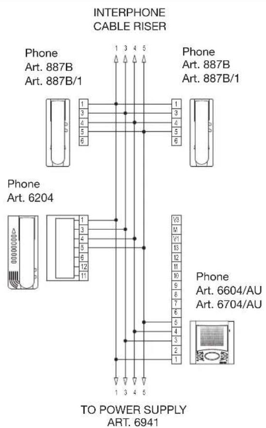
INTERPHONE RISER WITH FLOOR DISTRIBUTOR ART. 949B (A) AND WITHOUT DISTRIBUTOR (B). Ref. diagram si029, si028
The risers shown (Type A or B) must be included in all interphone diagrams given in this collection.
A- Distributor Art. 949B
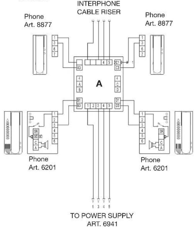
flowchart
graph TD
    subgraph Interphone Cable Riser
        A["Phone Art. 8877"] -->|A3, B1, B3| C["INTERPHONE CABLE RISER"]
        A -->|C1, C3| D["TO POWER SUPPLY ART. 6941"]
        A -->|D1, D3| E["TO POWER SUPPLY ART. 6201"]
    end
    F["Phone Art. 8877"] -->|1, 3, 6, 7| G["TO POWER SUPPLY ART. 6941"]
    H["Phone Art. 6201"] -->|1, 2, 3, 4, 5, 6| I["TO POWER SUPPLY ART. 6941"]
    J["SR"] --> K["Phone Art. 6201"]
    L["SD"] --> M["Phone Art. 6201"]
    N["C"] --> O["Phone Art. 6201"]
    P["A"] --> Q["Phone Art. 6201"]
    R["B"] --> S["Phone Art. 6201"]
    T["C"] --> U["Phone Art. 6201"]
SIMPLE RESIDENTIAL INSTALLATION WITH PORTER'S SWITCHBOARD
Ref. diagram si091
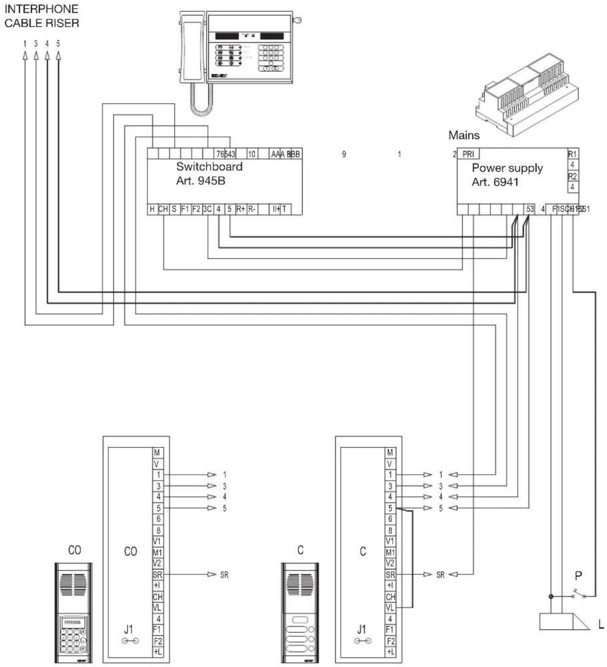
flowchart
graph TD
    A["INTERPHONE CABLE RISER"] --> B["Switchboard Art. 945B"]
    B --> C["Power supply Art. 6941"]
    C --> D["Mains"]
    D --> E["Control Panel L"]
    subgraph Interphone Cable Riser
        F["CO"] --> G["J1"]
        G --> H["SR"]
        H --> I["CH"]
        I --> J["V1"]
        J --> K["M1"]
        K --> L["V2"]
        L --> M["SR"]
        M --> N["+I"]
        N --> O["F1"]
        O --> P["F2"]
        P --> Q["L"]
    end
    subgraph Power Supply
        R["R1"] --> S["53"]
        T["R2"] --> U["4"]
        V["P"] --> W["4"]
        X["F"] --> Y["5"]
        Z["F1S"] --> AA["6"]
        AB["CH8"] --> AC["4"]
        AD["L"] --> AE["SR"]
    end
    F --> G
    G --> H
    H --> I
    I --> J
    J --> K
    K --> L
    L --> M
    M --> N
    N --> O
    O --> P
    P --> Q
    Q --> R
    R --> S
    S --> T
    T --> U
    U --> V
    V --> X
    X --> Y
    Y --> Z
    Z --> AA
    AA --> AB
    AB --> AC
    AC --> AD
    AD --> AE
C- Entrance panel with push-button Art. 8843 - 1283
C0-Entrance panel with keypad and display Art. 8844 - 1282
P- Additional push-button for lock
L- Electric lock 12V A.C.
RESIDENTIAL INTERPHONE INSTALLATION WITH ONE MAIN PANEL, PORTER'S SWITCHBOARD AND TWO OR MORE STAIRWAY PANELS (BUILDING COMPLEX).
Ref. diagram si094
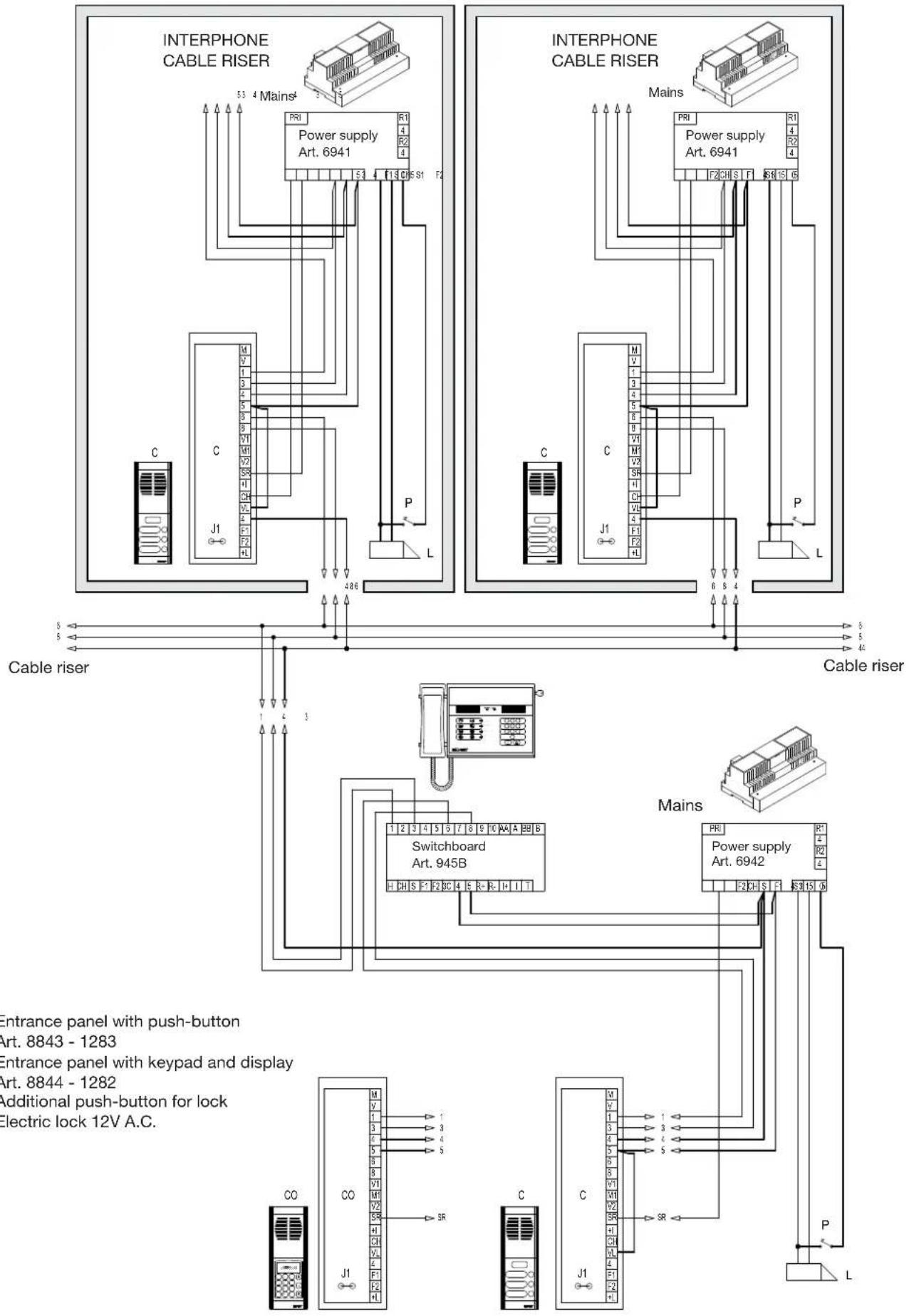
flowchart
graph TD
    subgraph_Interphone_Cable_Riser["Interphone Cable Riser"]
        A1["Cable riser"] --> B1["Switchboard Art. 945B"]
        A2["Cable riser"] --> B2["Switchboard Art. 945B"]
        A3["Cable riser"] --> B3["Switchboard Art. 945B"]
        A4["Cable riser"] --> B4["Switchboard Art. 945B"]
        A5["Cable riser"] --> B5["Switchboard Art. 945B"]
        A6["Cable riser"] --> B6["Switchboard Art. 945B"]
        A7["Cable riser"] --> B7["Switchboard Art. 945B"]
        A8["Cable riser"] --> B8["Switchboard Art. 945B"]
        A9["Cable riser"] --> B9["Switchboard Art. 945B"]
        A10["Cable riser"] --> B10["Switchboard Art. 945B"]
        A11["Cable riser"] --> B11["Switchboard Art. 945B"]
        A12["Cable riser"] --> B12["Switchboard Art. 945B"]
        A13["Cable riser"] --> B13["Switchboard Art. 945B"]
        A14["Cable riser"] --> B14["Switchboard Art. 945B"]
        A15["Cable riser"] --> B15["Switchboard Art. 945B"]
        A16["Cable riser"] --> B16["Switchboard Art. 945B"]
        A17["Cable riser"] --> B17["Switchboard Art. 945B"]
        A18["Cable riser"] --> B18["Switchboard Art. 945B"]
        A19["Cable riser"] --> B19["Switchboard Art. 945B"]
        A20["Cable riser"] --> B20["Switchboard Art. 945B"]
        A21["Cable riser"] --> B21["Switchboard Art. 945B"]
        A22["Cable riser"] --> B22["Switchboard Art. 945B"]
        A23["Cable riser"] --> B23["Switchboard Art. 945B"]
        A24["Cable riser"] --> B24["Switchboard Art. 945B"]
        A25["Cable riser"] --> B25["Switchboard Art. 945B"]
        A26["Cable riser"] --> B26["Switchboard Art. 945B"]
        A27["Cable riser"] --> B27["Switchboard Art. 945B"]
        A28["Cable riser"] --> B28["Switchboard Art. 945B"]
        A29["Cable riser"] --> B29["Switchboard Art. 945B"]
        A30["Cable riser"] --> B30["Switchboard Art. 945B"]
        A31["Cable riser"] --> B31["Switchboard Art. 945B"]
        A32["Cable riser"] --> B32["Switchboard Art. 945B"]
        A33["Cable riser"] --> B33["Switchboard Art. 945B"]
        A34["Cable riser"] --> B34["Switchboard Art. 945B"]
        A35["Cable riser"] --> B35["Switchboard Art. 945B"]
        A36["Cable riser"] --> B36["Switchboard Art. 945B"]
        A37["Cable riser"] --> B37["Switchboard Art. 945B"]
        A38["Cable riser"] --> B38["Switchboard Art. 945B"]
        A39["Cable riser"] --> B39["Switchboard Art. 945B"]
        A40["Cable riser"] --> B40["Switchboard Art. 945B"]
        A41["Cable riser"] --> B41["Switchboard Art. 945B"]
        A42["Cable riser"] --> B42["Switchboard Art. 945B"]
        A43["Cable riser"] --> B43["Switchboard Art. 945B"]
        A44["Cable riser"] --> B44["Switchboard Art. 945B"]
        A45["Cable riser"] --> B45["Switchboard Art. 945B"]
        A46["Cable riser"] --> B46["Switchboard Art. 945B"]
        A47["Cable riser"] --> B47["Switchboard Art. 945B"]
        A48["Cable riser"] --> B48["Switchboard Art. 945B"]
        A49["Cable riser"] --> B49["Switchboard Art. 945B"]
        A50["Cable riser"] --> B50["Switchboard Art. 945B"]
        A51["Cable riser"] --> B51["Switchboard Art. 945B"]
        A52["Cable riser"] --> B52["Switchboard Art. 945B"]
        A53["Cable riser"] --> B53["Switchboard Art. 945B"]
        A54["Cable riser"] --> B54["Switchboard Art. 945B"]
        A55["Cable riser"] --> B55["Switchboard Art. 945B"]
        A56["Cable riser"] --> B56["Switchboard Art. 945B"]
        A57["Cable riser"] --> B57["Switchboard Art. 945B"]
        A58["Cable riser"] --> B58["Switchboard Art. 945B"]
        A59["Cable riser"] --> B59["Switchboard Art. 945B"]
        A60["Cable riser"] --> B60["Switchboard Art. 945B"]
        A61["Cable riser"] --> B61["Switchboard Art. 945B"]
        A62["Cable riser"] --> B62["Switchboard Art. 945B"]
        A63["Cable riser"] --> B63["Switchboard Art. 945B"]
        A64["Cable riser"] --> B64["Switchboard Art. 945B"]
        A65["Cable riser"] --> B65["Switchboard Art. 945B"]
        A66["Cable riser"] --> B66["Switchboard Art. 945B"]
        A67["Cable riser"] --> B67["Switchboard Art. 945B"]
        A68["Cable riser"] --> B68["Switchboard Art. 945B"]
        A69["Cable riser"] --> B69["Switchboard Art. 945B"]
        A70["Cable riser"] --> B70["Switchboard Art. 945B"]
        A71["Cable riser"] --> B71["Switchboard Art. 945B"]
        A72["Cable riser"] --> B72["Switchboard Art. 945B"]
        A73["Cable riser"] --> B73["Switchboard Art. 945B"]
        A74["Cable riser"] --> B74["Switchboard Art. 945B"]
        A75["Cable riser"] --> B75["Switchboard Art. 945B"]
        A76["Cable riser"] --> B76["Switchboard Art. 945B"]
        A77["Cable riser"] --> B77["Switchboard Art. 945B"]
        A78["Cable riser"] --> B78["Switchboard Art. 945B"]
        A79["Cable riser"] --> B79["Switchboard Art. 945B"]
        A80["Cable riser"] --> B80["Switchboard Art. 945B"]
        A81["Cable riser"] --> B81["Switchboard Art. 945B"]
        A82["Cable riser"] --> B82["Switchboard Art. 945B"]
        A83["Cable riser"] --> B83["Switchboard Art. 945B"]
        A84["Cable riser"] --> B84["Switchboard Art. 945B"]
        A85["Cable riser"] --> B85["Switchboard Art. 945B"]
        A86["Cable riser"] --> B86["Switchboard Art. 945B"]
        A87["Cable riser"] --> B87["Switchboard Art. 945B"]
        A88["Cable riser"] --> B88["Switchboard Art. 945B"]
        A89["Cable riser"] --> B89["Switchboard Art. 945B"]
        A90["Cable riser"] --> B90["Switchboard Art. 945B"]
        A91["Cable riser"] --> B91["Switchboard Art. 945B"]
        A92["Cable riser"] --> B92["Switchboard Art. 945B"]
        A93["Cable riser"] --> B93["Switchboard Art. 945B"]
        A94["Cable riser"] --> B94["Switchboard Art. 945B"]
        A95["Cable riser"] --> B95["Switchboard Art. 945B"]
        A96["Cable riser"] --> B96["Switchboard Art. 945B"]
        A97["Cable riser"] --> B97["Switchboard Art. 945B"]
        A98["Cable riser"] --> B98["Switchboard Art. 945B"]
        A99["Cable riser"] --> B99["Switchboard Art. 945B"]
    end
    subgraph Cable_Riser
    C1
    C2
    C3
    C
    C
    C
    C
    C
    C
    C
    C
    C
    C
    C
    C
    C
    C
    C
    C
    C
    C
    C
    C
    C
    C
    C
    C
    C
    C
    C
    C
    C
    C
    C
    C
    C
    C
MONITOR CABLE RISER WITH UNITS EQUIPPED WITH INTERNAL DIGITAL SIGNAL DECODING. Ref. diagram si356
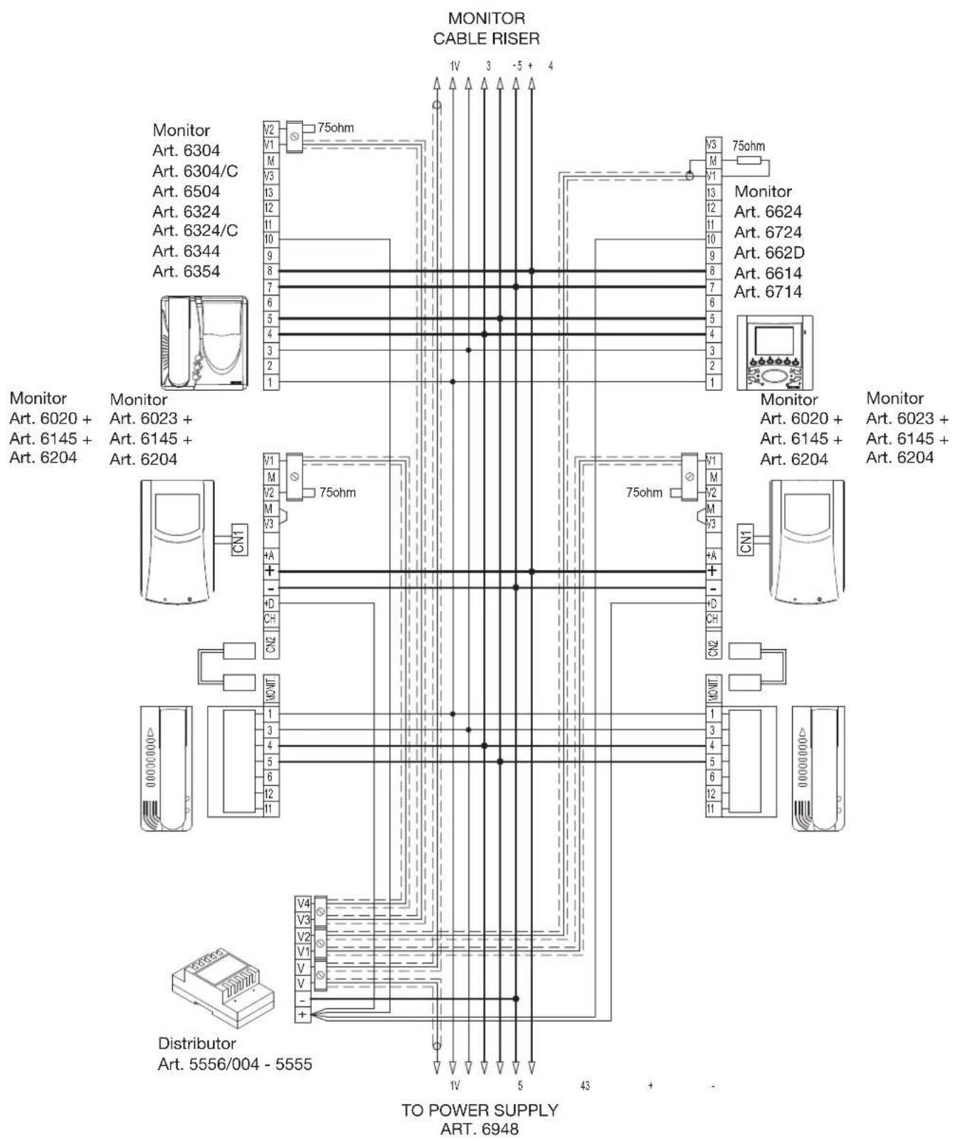
flowchart
graph TD
    subgraph Monitor_Cable_Riser
        A["Monitor Art. 6304"] -->|V2 75ohm| B["Monitor Art. 6624"]
        C["Monitor Art. 6304/C"] -->|M 13| D["Monitor Art. 6724"]
        E["Monitor Art. 6504"] -->|V3 12| F["Monitor Art. 662D"]
        G["Monitor Art. 6324"] -->|I1 11| H["Monitor Art. 6614"]
        I["Monitor Art. 6344"] -->|9 10| J["Monitor Art. 6714"]
        K["Monitor Art. 6354"] -->|8 7| L["Monitor Art. 6020 +"]
        M["Monitor Art. 6023 +"] --> N["Monitor Art. 6145 +"]
        O["Monitor Art. 6145 +"] --> P["Monitor Art. 6204"]
        Q["Monitor Art. 6204"] --> R["Monitor Art. 6020 +"]
        S["Distributor Art. 5556/004 - 5555"] --> T["TO POWER SUPPLY ART. 6948"]
    end
    subgraph Distributor
        U["V4 V3 V2 V1 V V"] --> V["V4 V3 V2 V1 V V"]
        W["V4 V3 V2 V1 V V"] --> X["V4 V3 V2 V1 V V"]
        Y["V4 V3 V2 V1 V V"] --> Z["V4 V3 V2 V1 V V"]
        AA["V4 V3 V2 V1 V V"] --> AB["V4 V3 V2 V1 V V"]
        AC["V4 V3 V2 V1 V V"] --> AD["V4 V3 V2 V1 V V"]
        AE["V4 V3 V2 V1 V V"] --> AF["V4 V3 V2 V1 V V"]
        AG["V4 V3 V2 V1 V V"] --> AH["V4 V3 V2 V1 V V"]
        AI["V4 V3 V2 V1 V V"] --> AJ["V4 V3 V2 V1 V V"]
        AK["V4 V3 V2 V1 V V"] --> AL["V4 V3 V2 V1 V V"]
        AM["V4 V3 V2 V1 V V"] --> AN["V4 V3 V2 V1 V V"]
        AO["V4 V3 V2 V1 V V"] --> AP["V4 V3 V2 V1 V V"]
        AQ["V4 V3 V2 V1 V V"] --> AR["V4 V3 V2 V1 V V"]
        AS["V4 V3 V2 V1 V V"] --> AT["V4 V3 V2 V1 V V"]
        AU["V4 V3 V2 V1 V V"] --> AV["V4 V3 V2 V1 V V"]
        AW["V4 V3 V2 V1 V"] --> AX["V4 V3 V2V"]
    end
    Monitor_Cable_Riser --> TO_POWER_Supply
    Monitor_Cable_Riser --> Distributor
    Distributor --> TO_POWER_Supply
    TO_POWER_Supply --> TO_POWER_Supply
    TO_POWER_Supply --> TO_POWER_Supply
    TO_POWER_Supply --> TO_POWER_Supply
    TO_POWER_Supply --> TO_POWER_Supply
    TO_POWER_Supply --> TO_POWER_Supply
    TO_POWER_Supply --> TO_POWER_Supply
The riser shown must be included in all the video interphone diagrams in this collection
MONITOR RISER WITH FLOOR DISTRIBUTOR ART. 949B
Ref. diagram si036
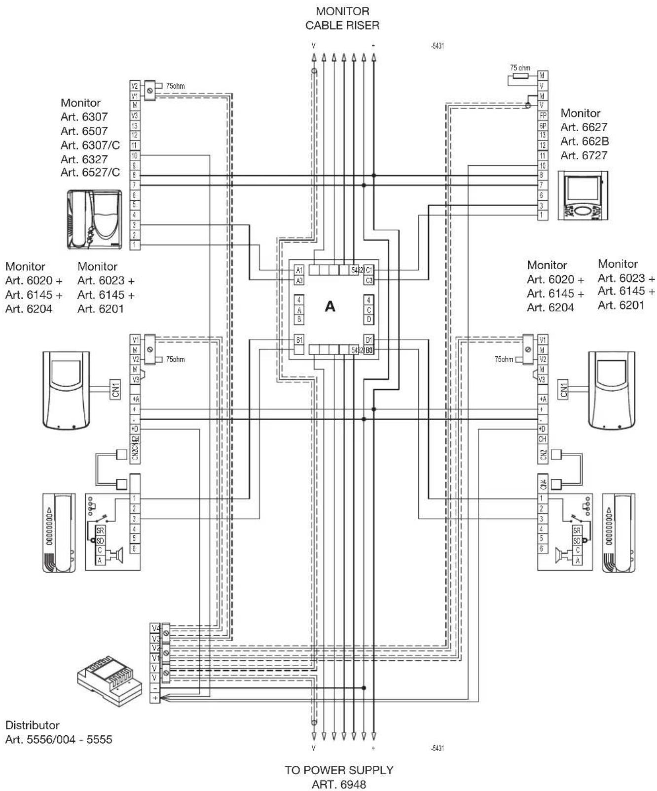
flowchart
graph TD
    subgraph MONITOR_CABLE_RISER
        V1["Monitor 6307"] -->|V2 75ohm| A["A"]
        V2["Monitor 6507"] -->|V3 13| A
        V3["Monitor 6307/C"] -->|V4 12| A
        V4["Monitor 6327"] -->|V5 11| A
        V5["Monitor 6527/C"] -->|V6 9| A
        V6["Monitor 6020 + Art. 6023 + Art. 6145 + Art. 6204"] -->|V7 8| A
        V7["Monitor 6020 + Art. 6023 + Art. 6145 + Art. 6204"] -->|V8 7| A
        V8["Monitor 6020 + Art. 6023 + Art. 6145 + Art. 6204"] -->|V9 6| A
        V9["Monitor 6020 + Art. 6023 + Art. 6145 + Art. 6204"] -->|V10 5| A
        V10["Monitor 6020 + Art. 6023 + Art. 6145 + Art. 6204"] -->|V11 4| A
        V11["Monitor 6020 + Art. 6023 + Art. 6145 + Art. 6204"] -->|V12 3| A
        V12["Monitor 6020 + Art. 6023 + Art. 6145 + Art. 6204"] -->|V13 2| A
        V13["Monitor 6020 + Art. 6023 + Art. 6145 + Art. 6204"] -->|V14 1| A
        V14["Monitor 6020 + Art. 6023 + Art. 6145 + Art. 6204"] -->|V15 0| A
        V15["Monitor 6020 + Art. 6023 + Art. 6145 + Art. 6204"] -->|V16 9| A
        V16["Monitor 6020 + Art. 6023 + Art. 6145 + Art. 6204"] -->|V17 8| A
        V17["Monitor 6020 + Art. 6023 + Art. 6145 + Art. 6204"] -->|V18 7| A
        V18["Monitor 6020 + Art. 6023 + Art. 6145 + Art. 6204"] -->|V19 6| A
        V19["Monitor 6020 + Art. 6023 + Art. 6145 + Art. 6204"] -->|V20 5| A
        V20["Monitor 6020 + Art. 6023 + Art. 6145 + Art. 6204"] -->|V21 4| A
        V21["Monitor 6020 + Art. 6023 + Art. 6145 + Art. 6204"] -->|V22 3| A
        V22["Monitor 6020 + Art. 6023 + Art. 6145 + Art. 6204"] -->|V23 2| A
        V23["Monitor 6020 + Art. 6023 + Art. 6145 + Art. 6204"] -->|V24 1| A
        V24["Monitor 6020 + Art. 6023 + Art. 6145 + Art. 6204"] -->|V25 0| A
        V25["Monitor 6020 + Art. 6023 + Art. 6145 + Art. 6204"] -->|V26 9| A
        V26["Monitor 6020 + Art. 6023 + Art. 6145 + Art. 6204"] -->|V27 8| A
        V27["Monitor 6020 + Art. 6023 + Art. 6145 + Art. 6204"] -->|V28 7| A
        V28["Monitor 6020 + Art. 6023 + Art. 6145 + Art. 6204"] -->|V29 6| A
        V29["Monitor 6020 + Art. 6023 + Art. 6145 + Art. 6204"] -->|V30 5| A
        V30["Monitor 6020 + Art. 6023 + Art. 6145 + Art. 6204"] -->|V31 4| A
        V31["Monitor 6020 + Art. 6023 + Art. 6145 + Art. 6204"] -->|V32 3| A
        V32["Monitor 6020 + Art. 6023 + Art. 6145 + Art. 6204"] -->|V33 2| A
        V33["Monitor 6020 + Art. 6023 + Art. 6145 + Art. 6204"] -->|V34 1| A
        V34["Monitor 6020 + Art. 6023 + Art. 6145 + Art. 6204"] -->|V35 0| A
        V35["Monitor 6020 + Art. 6023 + Art. 6145 + Art. 6204"] -->|V36 9| A
        V36["Monitor 6020 + Art. 6023 + Art. 6145 + Art. 6204"] -->|V37 8| A
        V37["Monitor 6020 + Art. 6023 + Art. 6145 + Art. 6204"] -->|V38 7| A
        V38["Monitor 6020 + Art. 6023 + Art. 6145 + Art. 6204"] -->|V39 6| A
        V39["Monitor 6020 + Art. 6023 + Art. 6145 + Art. 6204"] -->|V40 5| A
        V40["Monitor Cables Riser"]
    end
A- Distributor Art. 949B
The riser shown must be included in all the video interphone diagrams in this collection
SIMPLE RESIDENTIAL INSTALLATION WITH PORTER'S SWITCHBOARD Ref. diagram si215
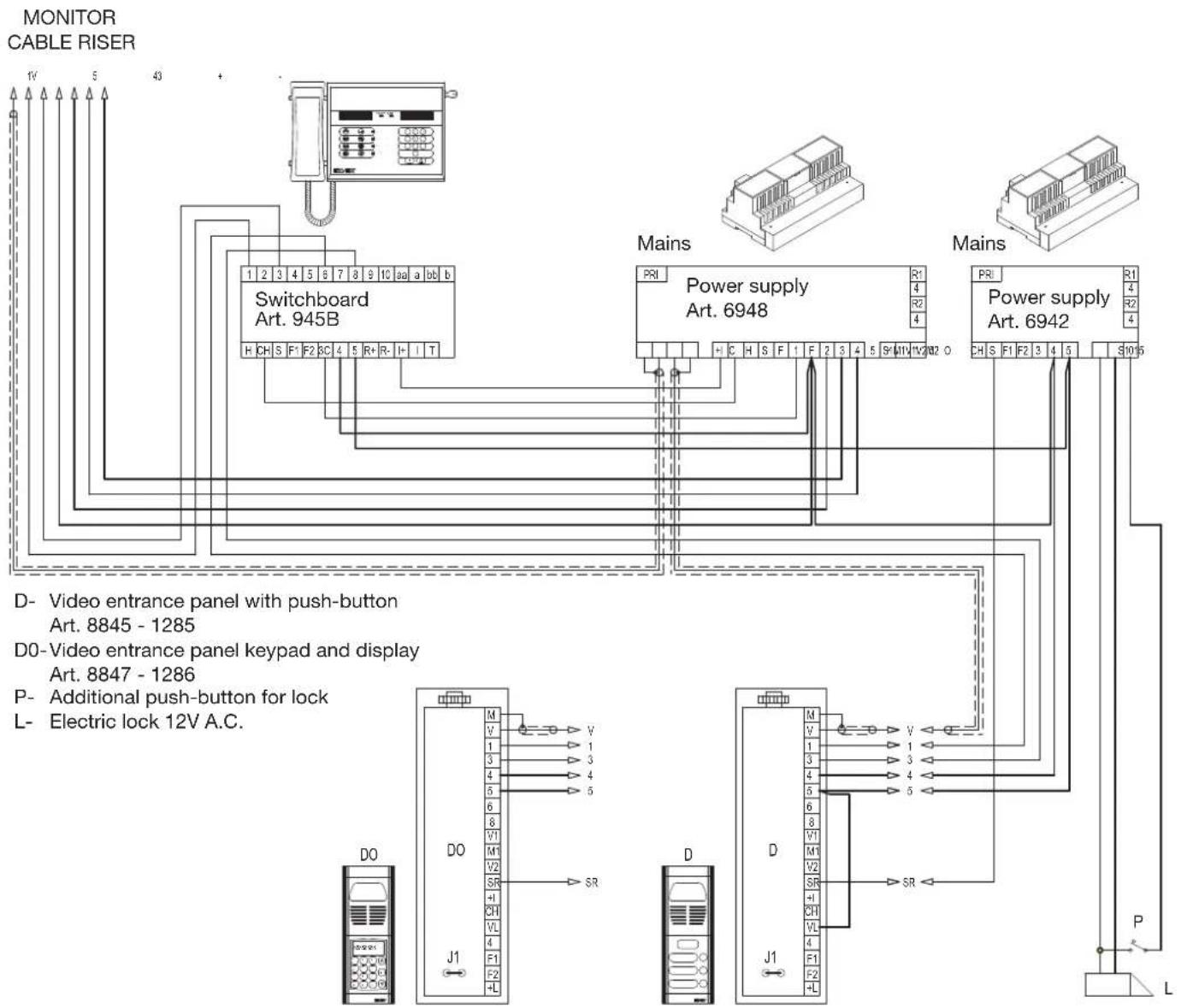
flowchart
graph TD
    A["MONITOR CABLE RISER"] --> B["Switchboard Art. 945B"]
    A --> C["Mains"]
    A --> D["Power supply Art. 6948"]
    A --> E["Power supply Art. 6942"]
    B --> F["D- Video entrance panel with push-button Art. 8845 - 1285"]
    B --> G["D0-Video entrance panel keypad and display Art. 8847 - 1286"]
    B --> H["P- Additional push-button for lock L- Electric lock 12V A.C."]
    C --> I["D- Power supply Art. 6948"]
    C --> J["D0-Video entrance panel with push-button Art. 8845 - 1285"]
    C --> K["D0-Video entrance panel keypad and display Art. 8847 - 1286"]
    D --> L["D- Power supply Art. 6942"]
    D --> M["D0-Video entrance panel with push-button Art. 8845 - 1285"]
    D --> N["D0-Video entrance panel keypad and display Art. 8847 - 1286"]
    E --> O["D- Power supply Art. 6942"]
    E --> P["D0-Video entrance panel with push-button Art. 8845 - 1285"]
    E --> Q["D0-Video entrance panel keypad and display Art. 8847 - 1286"]
    style A fill:#f9f,stroke:#333
    style B fill:#ccf,stroke:#333
    style C fill:#cfc,stroke:#333
    style D fill:#fcc,stroke:#333
    style E fill:#cff,stroke:#333
    style F fill:#ffc,stroke:#333
    style G fill:#ffc,stroke:#333
    style H fill:#ffc,stroke:#333
    style I fill:#ffc,stroke:#333
    style J fill:#ffc,stroke:#333
    style K fill:#ffc,stroke:#333
    style L fill:#ffc,stroke:#333
    style M fill:#ffc,stroke:#333
    style N fill:#ffc,stroke:#333
    style O fill:#ffc,stroke:#333
    style P fill:#ffc,stroke:#333
    style Q fill:#ffc,stroke:#333
RESIDENTIAL VIDEO ENTRY INSTALLATION WITH ONE MAIN PANEL, PORTER'S SWITCHBOARD AND TWO OR MORE STAIRWAY PANELS (BUILDING COMPLEX).
Ref. diagram si317
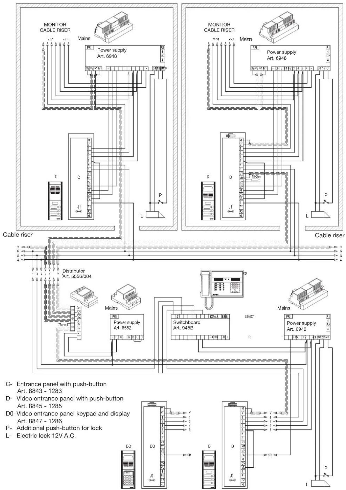
flowchart
graph TD
    subgraph Power Riser
        A["MONITOR CABLE RISER"] --> B["Mains"]
        B --> C["PRI"]
        C --> D["Power supply Art. 6948"]
        D --> E["S1 S2 S3 S4 S5 S6 S7 S8 S9 S10 S11 S12 S13 S14 S15 S16 S17 S18 S19 S20 S21 S22 S23 S24 S25 S26 S27 S28 S29 S30 S31 S32 S33 S34 S35 S36 S37 S38 S39 S40<br>    end<br><br>    subgraph Cable Riser<br>        E --> F[Cable riser"]
        F --> G["Distributor Art. 5556/004"]
        G --> H["Mains"]
        H --> I["PRI"]
        I --> J["Power supply Art. 6582"]
        J --> K["Switchboard Art. 945B"]
        K --> L["R"]
        L --> M["Power supply Art. 6942"]
    end

    subgraph Display Panel
        N["C- Entrance panel with push-button Art. 8843 - 1283"] --> O["D- Video entrance panel with push-button Art. 8845 - 1285"]
        P["D0- Video entrance panel keypad and display Art. 8847 - 1286"] --> Q["P- Additional push-button for lock"]
        R["L- Electric lock 12V A.C."] --> S["L"]
    end

    style Power Riser fill:#f9f,stroke:#333
    style Cable Riser fill:#ccf,stroke:#333
    style Display Panel fill:#cfc,stroke:#333
BASIC DIAGRAM VERSIONS
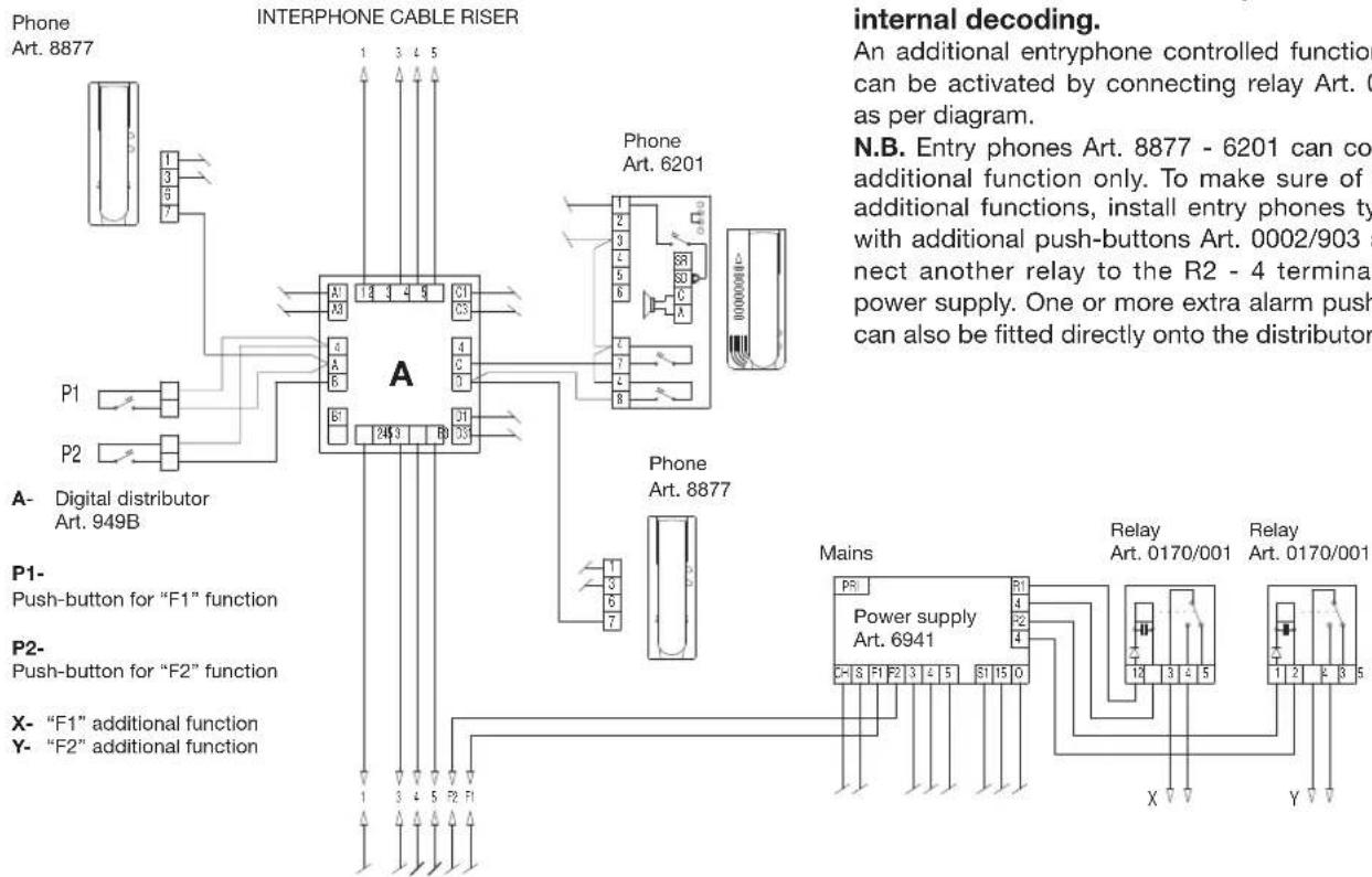
VERSION 1A
flowchart
graph TD
    subgraph PhoneArt_8877
        A["Phone Art. 8877"] --> B["INTERPHONE CABLE RISER"]
        B --> C["Phone Art. 6201"]
        C --> D["Internal Decoding"]
    end

    subgraph DigitalDistributorArt_949B
        E["P1"] --> F["Push-button for "F1" function"]
        G["P2"] --> H["Push-button for "F2" function"]
        I["X- "F1" additional function Y- "F2" additional function"]
    end

    subgraph PowerSupplyMains
        J["Power supply Art. 6941"] --> K["Relay Art. 0170/001"]
        L["Relay Art. 0170/001"] --> M["Relay Art. 0170/001"]
    end

    style A fill:#f9f,stroke:#333
    style B fill:#ccf,stroke:#333
    style C fill:#cfc,stroke:#333
    style D fill:#fcc,stroke:#333
    style E fill:#ffc,stroke:#333
    style F fill:#cfc,stroke:#333
    style G fill:#ffc,stroke:#333
    style H fill:#cfc,stroke:#333
    style I fill:#ffc,stroke:#333
    style J fill:#cfc,stroke:#333
    style K fill:#cfc,stroke:#333
    style L fill:#cfc,stroke:#333
    style M fill:#cfc,stroke:#333
Supplementary function F1-F2 connections in installations with interphones without internal decoding.
An additional entryphone controlled function (F1-F2) can be activated by connecting relay Art. 0170/001 as per diagram.
N.B. Entry phones Art. 8877 - 6201 can control one additional function only. To make sure of both the additional functions, install entry phones type 6201 with additional push-buttons Art. 0002/903 and connect another relay to the R2 - 4 terminals of the power supply. One or more extra alarm push-buttons can also be fitted directly onto the distributor (P1-P2).
VERSION 1B
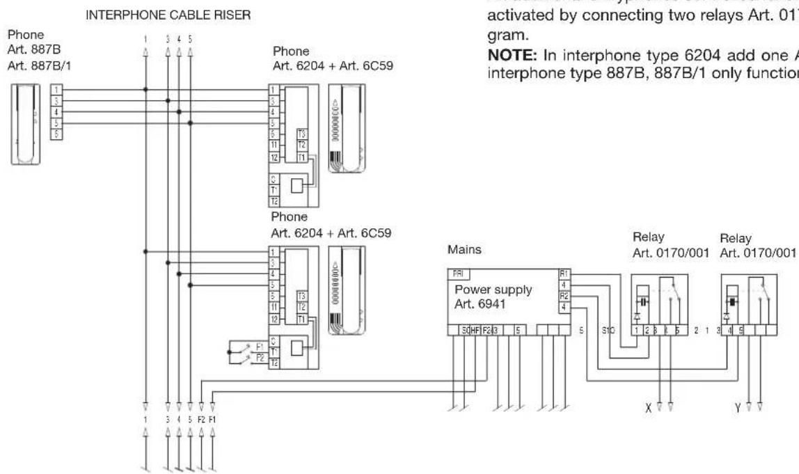
X- "F1" additional function
Y- "F2" additional function
BASIC DIAGRAM VERSIONS
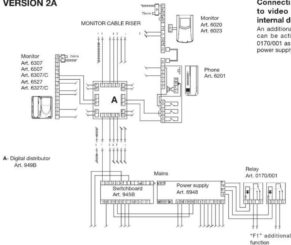
VERSION 2A
flowchart
graph TD
    A["Monitor Cable Riser"] --> B["Switchboard Art. 945B"]
    A --> C["Power supply Art. 6948"]
    B --> D["Relay Art. 0170/001"]
    C --> E[""F1" additional function"]
    F["Phone Art. 6201"] --> G["Monitor Art. 6020 Art. 6023"]
    H["Monitor Art. 6307 Art. 6507 Art. 6307/C Art. 6527 Art. 6327/C"] --> I["750nm"]
    style A fill:#f9f,stroke:#333
    style B fill:#ccf,stroke:#333
    style C fill:#cfc,stroke:#333
    style D fill:#fcc,stroke:#333
    style E fill:#cff,stroke:#333
    style F fill:#ffc,stroke:#333
    style G fill:#fcf,stroke:#333
    style H fill:#cff,stroke:#333
    style I fill:#ffc,stroke:#333
Connecting additional function F1 to video door entry systems with internal decoding.
An additional monitor controlled function (F1) can be activated by connecting relay Art. 0170/001 as per diagram (terminals R1-4 of the power supply).
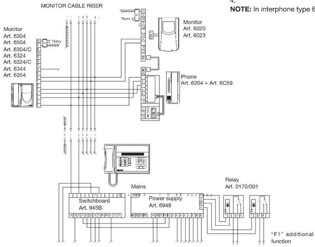
VERSION 2B
flowchart
graph TD
    A["Monitor Cable Riser"] --> B["75ohm"]
    B --> C["Monitor Art. 6020 Art. 6023"]
    B --> D["Phone Art. 6204 + Art. 6C59"]
    B --> E["Mains"]
    E --> F["Switchboard Art. 945B"]
    E --> G["Power supply Art. 6948"]
    E --> H["Relay Art. 0170/001"]
    style A fill:#f9f,stroke:#333
    style B fill:#ccf,stroke:#333
    style C fill:#cfc,stroke:#333
    style D fill:#fcc,stroke:#333
    style E fill:#cff,stroke:#333
    style F fill:#ffc,stroke:#333
    style G fill:#cfc,stroke:#333
    style H fill:#fcc,stroke:#333
Connecting additional function F1 to video door entry systems with internal decoding.
An additional monitor controlled function F1 can be activated by connecting relay Art. 0170/001 as per diagram (terminals R1-4 of the power supply).
For the auxiliary function F2 insert a relay type 0170/001 and connect it to power supply terminals R2-4.
NOTE: In interphone type 6204 add one Art. 6C59.
BASIC DIAGRAM VERSIONS
VERSION 3
External chime connection for call repeater on the switchboard.
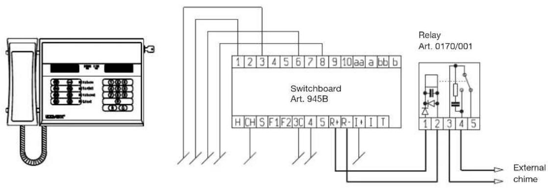
DIAGRAM SYMBOLS

A.C. buzzer

Lamp

Loudspeaker

A.C. supply from mains

A.C. bell

Push-button

Amplified microphone

Ground

Electric lock

Switch

Receiver

Coaxial cable grip
MAIN IMPROVEMENTS/SOFTWARE MODIFICATIONS APPLIED:
1) POSSIBILITY OF EXTERNAL REPETITION OF CALL RINGTONES (via external relay if fitted): or with the setting (entering Parameter Programming mode using keys R+4) "TIME_F2"=0 to enable ringtone repetition on terminal F2. In practice in this mode, function F2 is no longer enabled (i.e. the command is no longer received or conveyed) and terminal P2 of the control unit connector becomes available for activation of an additionalo ringtone.
Repetition of this ringtone can be enabled (if required) on calls from interphones and/or from F1 and from an external panel. On each call, the line of terminal F2 is activated (for approx. 2 seconds), which can be connected to an acoustic repeater (the terminal is closed to earth)..
2) TRANSIT OF CALLS FROM EXTERNAL ENTRANCE PANEL:- The parameter "Ab.Transi.Esterno" has been inserted at the end of the programming parameters. If set to 1, external incoming calls (on terminal 6 connected to the external entrance panel) always transit "upline" (to interphone/monitor riser) even when the switchboard is set to Internal mode (in which case the operator never needs to intervene on external calls to the interphone cable riser). If set to 0, this function is disabled (i.e. direct transit is only active when the switchboard is set to External mode).
3) MANUAL ACTIVATION OF AUDIO LINE TO CABLE RISER: The audio to the cable riser is activated manually by pressing the conference key for at least 3 sec. This is useful to enable the voice communication with an interphone during the programming phase (similar to 945A) to enable voice communication with the technician at the interphone.
4) IMPROVEMENTS: If an interphone does not answer, when the handset is replaced the cable riser is disengaged virtually immediately (after 3 sec) eliminating the need to wait for the "answer standby" timeout to elapse (this was usually 30-45 seconds, during which the cable riser remained engaged).
5) VIEW function added to the new Digibus commands of : Enter programming ("Ent.Prog.N"). Programming complete ("Prog.Int.N") of the interphones and the new door burglar alarm command ("! ALARMS.N") for type 6158.
NB: The new digibus interphones confirm entry to programming mode and memorisation of a new number by sending specific commands on the digital signal, which can now be verified via the switchboard or numerical entrance panel if fitted (set to debug).
NOTES ON FUNCTIONS F1, F2, DOOR LOCK, F6, F7, F8.
1) Functions F1 and F2: When the switchboard receives a command related to these functions (from an interphone) it always activates the specific terminal (F1 or F2).
At the same time, the command is re-sent "downline", i.e. to the serial line of the external DIGITAL signals connected to terminal 6 (NB: Repetition may, if necessary, be suppressed; in this case contact ELVOX Spa for assistance). When these functions are activated by means of the "'KEY" button, the functions are always activated in local mode (on the switchboard terminal) and re-sent to the device downline (connected terminal 6 of the digital signal).
NB: When terminal F2 is set with the time =0 it performs exclusively the function of Call Repetition, but the option remains for it to be activated (for approx. 2. seconds) by means of the "KEY" button (with no command transmission).
2) DOOR LOCK RELEASE function: When the switchboard receives a door lock release command, it always activates its specific terminal "S" connected to the local lock. The command is only resent on the external serial line if communication with an external entrance panel is in progress (and therefore does not occur if the switchboard communicates with an interphone). In the same way, the "KEY" button always activates the local lock, and the command is sent "down" only when there is communication in progress with an external entrance panel. Obviously if the user wishes to always activate the release of a lock connected to an external entrance panel (also when not connected), terminal 5 of the switchboard must be connected in parallel to terminal 5 of the panel.
NB: If the switchboard is in communication when a secondary entrance panel "upline" (and therefore "switched audio" mode) the lock can be opened on this panel (if the parameter "lock enable" on this panel is set to =2 or 3).
3) Functions F6, F7, F8: When the switchboard receives these commands from the cable riser upline, it always repeats them towards the external digital signal. In the same way, if these functions are activated via the "KEY" button, the command is sent to the external serial line (completed with the digibus number of the switchboard). These functions are useful to enable activation of external devices via type I70/D or 170/F (currently prototypes only).
Installation rules
Installation should be carried out by qualified personnel in compliance with the current regulations regarding the installation of electrical equipment in the country where the products are installed.
Conformity
EMC directive
Standards EN 60065, EN 61000-6-1 and EN 61000-6-3.
REACH (EU) Regulation no. 1907/2006 – Art.33. The product may contain traces of lead.

WEEE - Information for users
If the crossed-out bin symbol appears on the equipment or packaging, this means the product must not be included with other general waste at the end of its working life. The user must take the worn product to a sorted waste center, or return it to the retailer when purchasing a new one. Products for disposal can be consigned free of charge (without any new purchase obligation) to retailers with a sales area of at least 400m ^2 , if they measure less than 25cm. An efficient sorted waste collection for the environmentally friendly disposal of the used device, or its subsequent recycling, helps avoid the potential negative effects on the environment and people's health, and encourages the re-use and/or recycling of the construction materials.
- DESCRIPTION
- MANAGING THE DISPLAY (40X2):
- UPPER LINE
- LOWER LINE
- "ICON" DESCRIPTION
- QUICK GUIDE
- STORED CALLS
- INTERNAL WATCH WITH DATE AND TIME AND 2 WAKE UP SERVICES
- AUDIO EVENTS
- "SOFTWARE" LOCK KEY
- SIMPLIFIED MANAGEMENT OF THE "INTERNAL-EXTERNAL" MODE PUSH-BUTTON.
- MANAGING THE PRINTER
- CIRCUIT BOARD RE-PROGRAMMING "IN-CIRCUIT".
- POSSIBLE CONNECTION TOWARD A PC
- PROGRAMMING THE SWITCHBOARD PARAMETERS
- A) Entry to programming mode using the front switchboard keypad
- Switchboard technical parameters table
- OPERATION
- DISPLAYING THE TIME - DATE - WAKE UP TIME-TABLE
- ACTIVATION OF LOCK RELEASE, F1, F2 AND OF THE ACCESSORIES FUNCTIONS F6, F7, F8:
- SELECT OPEN?
- SWITCHBOARD LOCK BY MEANS OF A SOFTWARE KEY
- QUEUE OF STORED CALLS:
- PROGRAMMING MENU
- 1) PROGRAMMING THE COMMANDS TO BE STORED ("COM. TO MEMO" on display):
- 2) PROGRAMMING THE COMMANDS TO PRINT ("COM. TO PRINT" on display):
- 3) PROGRAMMING THE WAKE UP SERVICE N. 1 ("RING 1 (hhmm) on display):
- 4) PROGRAMMING THE WAKE UP SERVICE N. 2 ("RING 2 (hhmm)" on display):
- ) PROGRAMMING THE TIME ("TIME (hhmm) on display):
- 6) PROGRAMMING THE DATE (DATE "gg mm aa") on display)
- PRINTING ACTIVATION
- SETTING THE TYPE OF PRINTER
- TO FORCE THE EXPULSION OF THE PRINTER PAPER
- ADVISED PRINTERS
- TO LISTEN TO/SHORTEN THE MELODIES:
- DOWNLOADING A NEW MELODY:
- MEANING OF THE MAIN TECHNICAL CHARACTERS
- DESCRIPTION OF SWITCHBOARD KEYPAD
- DESCRIPTION OF KEYPAD
- Left hand section:
- Right hand section:
- Buttons R and 4PROGRAMMING ACCESS:
- Keypad lamps in central section of switchboard:
- EXTERNAL operation (lamp EXTERNAL "on").
- INTERNAL operation ("EXTERNAL" lamp "off").
- ADJUSTMENTS AND DESCRIPTION OF TERMINALS
- Adjustment trimmers
- Switchboard terminals.
- INTERPHONE RISER WITH FLOOR DISTRIBUTOR ART. 949B (A) AND WITHOUT DISTRIBUTOR (B). Ref. diagram si029, si028
- RESIDENTIAL INTERPHONE INSTALLATION WITH ONE MAIN PANEL, PORTER'S SWITCHBOARD AND TWO OR MORE STAIRWAY PANELS (BUILDING COMPLEX).
- MONITOR RISER WITH FLOOR DISTRIBUTOR ART. 949B
- Ref. diagram si036
- SIMPLE RESIDENTIAL INSTALLATION WITH PORTER'S SWITCHBOARD Ref. diagram si215
- RESIDENTIAL VIDEO ENTRY INSTALLATION WITH ONE MAIN PANEL, PORTER'S SWITCHBOARD AND TWO OR MORE STAIRWAY PANELS (BUILDING COMPLEX).
- BASIC DIAGRAM VERSIONS
- VERSION 3
- DIAGRAM SYMBOLS
- MAIN IMPROVEMENTS/SOFTWARE MODIFICATIONS APPLIED:
- NOTES ON FUNCTIONS F1, F2, DOOR LOCK, F6, F7, F8.
- Installation rules
- Conformity
- WEEE - Information for users
Brand : Vimar
Model : ELVOX 945B
Category : Switch