
01595 - Software Vimar - Free user manual and instructions
Find the device manual for free 01595 Vimar in PDF.


| Product Type | Power Socket with USB Charging |
| Brand | Vimar |
| Model | 01595 |
| Dimensions | 80 x 80 x 40 mm |
| Weight | 110 g |
| Material | Polycarbonate, Anti-UV |
| Color | White (RAL 9010) |
| Rated Voltage | 230 V AC, 50/60 Hz |
| Rated Current | 16 A |
| USB Output | 5 V DC, 2.4 A (shared) |
| Protection Rating | IP20 (indoor use) |
| Operating Temperature | -5°C to 40°C |
| Installation Type | Flush mounting, 60 mm box |
| Connection Type | Screw terminals, up to 2.5 mm² |
| Key Features | USB charging, child safety shutter, anti-corrosion springs |
| Maintenance | Wipe with dry cloth; no solvents |
| Safety | Complies with EN 60884-1, CE marked |
| Included Accessories | Mounting screws, instruction manual |
Frequently Asked Questions - 01595 Vimar
User questions about 01595 Vimar
0 question about this device. Answer the ones you know or ask your own.
Ask a new question about this device
Download the instructions for your Software in PDF format for free! Find your manual 01595 - Vimar and take your electronic device back in hand. On this page are published all the documents necessary for the use of your device. 01595 by Vimar.
USER MANUAL 01595 Vimar
Software for interfacing with management systems
Installation, configuration and user manual
Vimar end-user license contract
VIMAR SPA located in Maroslica (VI), Viale Vicenza n. 14 (http://www.vimar.com), sole owner of the software named "Software Interfacciamento Sistemi Gestionali", through this contract grants the license of use of the aforementioned program.
VIMAR SPA shall not be held liable for any damage caused by improper use of the aforementioned software, in particular for direct or indirect damage to persons, property, and/or animals due to economic loss that may occur as a result of the use of the software.
VIMAR SPA reserves the right to make any changes to improve the function of the aforementioned software without advance notice.
It is prohibited to modify, translate, adapt, or create applications based on the aforementioned software, without previous written consent from VIMAR.
The user must verify the suitability of the program to his needs, and interpret the results to verify the consequences of the choices of design made.
All risks concerning the results and performance of the program are assumed by the user.
VIMAR SPA holds the exclusive property right of the software.
Unauthorized duplication of the program is prohibited.
It is expressly forbidden to modify, translate, fit, change, disassembly in any way or to create by-products from the software.
The user is to be held responsible not to eliminate any information of the software relevant to the Copyright.
The software are protected under the Copyright laws in force in Italy and foreseen by the International treaties, therefore, any activity realized in contrast with what is stated above, will be prosecuted at the right place.
VIMAR SPA
Viale Vicenza, 14
36063 Marostica VI - Italy
http://www.vimar.com
Microsoft, Windows, Vista and Media Center are Microsoft Corporation trademarks in the USA and/or other countries.
INDEX
DESCRIPTION OF THE SOFTWARE FOR INTERFACING WITH MANAGEMENT SYSTEMS (ART. 01595) 2
Operations 2
Other Characteristics 2
INSTALLATION 3
HOW TO INSTALL THE SOFTWARE 4
SOFTWARE UPDATE 4
CONFIGURATION 5
INTRODUCTION 6
CONFIGURATION OF INTERFACING WITH MANAGEMENT SYSTEMS 6
License Activation 7
Selecting and configuring the administrative management system 7
MICROS-FIDELIO MANAGEMENT SOFTWARE 9
Introduction 9
Selecting and configuring the PMS 9
NI.CE. INFORMATICA MANAGEMENT SOFTWARE - HOTEL2000 14
Introduction.... 14
Selecting and configuring the PMS 14
HOTEL MANAGEMENT SOFTWARE - LEONARDO.... 20
Introduction.... 20
Selecting and configuring the PMS 20
OTHER PMS ADOPTING THE WCS PROTOCOL 26
Introduction.... 26
Selecting and configuring the PMS 26
USE 33
SOFTWARE START UP 34
MICROS-FIDELIO MANAGEMENT SOFTWARE 34
Introduction.... 34
Exchanged data 34
Micros-Fidelio operations and effects on the WCS 35
NI.CE. INFORMATICA MANAGEMENT SOFTWARE - HOTEL2000 36
Introduction.... 36
Exchanged data 36
Ni.Ce. Informatica Operations - Hotel2000 operations and effects on the WCS 37
HOTEL MANAGEMENT SOFTWARE - LEONARDO 38
Introduction.... 38
Exchanged data 38
Hotel Management - Leonardo operations and effects on the WCS 39
OTHER PMS ADOPTING THE WCS PROTOCOL 40
Introduction 40
Exchanged data 40
Used PMS operations and effects on the WCS 41
Description of the software for interfacing with management systems (art. 01595)
The software for interfacing with management systems makes it possible the exchange of information between the main administrative management software (Property Management System, also known as PMS in this manual) used for the administration of the hotel and the Well-Contact Suite Software (Basic cod. 01590 or Top cod. 01591, also known as WCS in this manual).
IMPORTANT:
Each PMS provides its own protocol for data communication. If the PMS is not among those already managed by the software for interfacing with management systems, the communication won't be possible. In this case it is necessary to communicate this failure to the provider of the management system, as well as to Vimar, requesting for the necessary developments to be undertaken.
Operations
- Exchange of the main personal data related to customer and reservation, from the PMS to the WCS Software, with automatic creation of customer and reservation card.
- Writing and automatic activation of the card.
• Automatic deactivation of the keys at Check-Out.
Other Characteristics
The software for interfacing with the management systems does not provide a user interface.
INSTALLATION SECTION
How to install the software
The software for interfacing with the management systems will be automatically installed with the Well-Contact Suite Basic Software (cod. 01590) or Well-Contact Suite Top Software (cod. 01591) Unless you activate the service-specific license, this component is non-operational.
To activate the license you must follow the appropriate procedure described in License Activation.
After properly installing the WCS software, so that it can be used with all its features, you need to perform the appropriate configuration described in the Chapter Configuration of the interfacing with management software.
The configuration operations can be performed only by software users with high access privilege to the software.
Software update
The software for interfacing with the management systems will be automatically updated with the WCS Software. To update the software, proceed as described in the user manual of the WCS software installed.
CONFIGURATION SECTION
Introduction
After properly installing the WCS software, so that it can be used with all its features, you need to perform the appropriate configuration. These operations are described in detail in the next few paragraphs. In the chapter Configuration of the interfacing with management software are described the generic operations that apply to all types of management software, while the next few chapters describe the operations to perform for each PMS compatible system.
Configuration of the interfacing with management software
Log on to the "General Interfacing Activation/Configuration" section from the menu "Settings" as described in Picture 1.
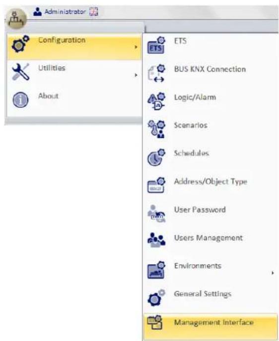
Picture 1 - Management Interfacing Activation / Configuration Menu
The window shown in Picture 2 appears. From this window, if the component is not yet activated the Request Build and Run buttons are selectable while the selection of the specific management software is not possible.
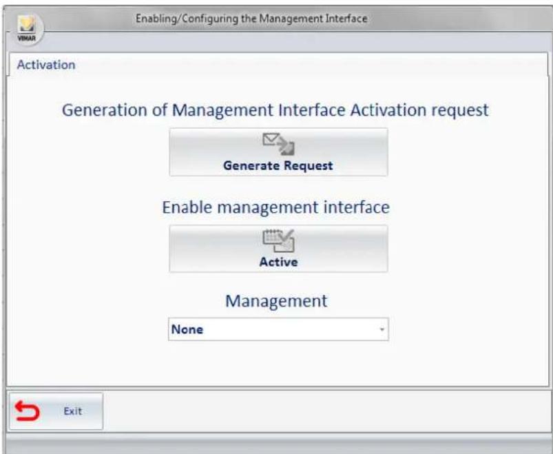
Picture 2 - Activation / Configuration Window if not yet activated
The "Well-Contact suite integrated software for interfacing with administrative management software" must be activated with an ad hoc procedure described in the following paragraph.
License Activation
To activate the interfacing with the management software you need follow the steps listed below:
- press the Generate Request button and select the folder to save the request file (it is suggested to use the My Documents folder);
- access the site www.vimar.com go to Products -> Product Software and select the requested item WCS-management interface activation;
- fill out the form by following the instructions and attach the file you just created;
- upon receipt of a response file, click on Activate to complete the activation and you will be asked to select the file generated for the request (.xreq extension) and, immediately after, the one received (.xresp extension). If all goes well, you will see the message shown in Picture 3.
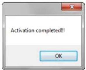
Picture 3 - Activation successful alert
Clicking OK you will return to Management Interfacing Activation/Configuration window, that will look as follows; because the component has been activated, the Generate Request and Activate buttons are no longer selectable, while it is finally possible to select the management software.

Picture 4 Activation / Configuration Window if activated
Selecting and configuring the administrative management system
From the multiple choice select the PMS used, after which more options will be available for the configuration of the selected system components. The newly available options are a subset of the list below:
- Connection to the Bus: generic parameters required for each management system; it collects the data necessary to enable the communication of the interface component with the system.
- Communication parameters: mandatory for all management systems; it collects the data necessary to enable the communication between the PMS and the WCS system;
- Card Programmers: it contains the transcoding table of the card programmers which can be specified from the PMS, name;
- Common Access: transcoding table of the common access (pool, sauns, garage, ...).
In Picture 5, for example, MICROS Fidelio ^1 , one of the PMSs managed at the time of the writing of this manual, is selected. You may notice the presence of all the options listed above. The following paragraphs describe the procedures to enter the data of the listed components.

Picture 5 - Activation / Configuration Window if a PMS is selected
Specifying the Bus Connection parameters
Selecting Bus Connection, you will see what shown in Picture 6.
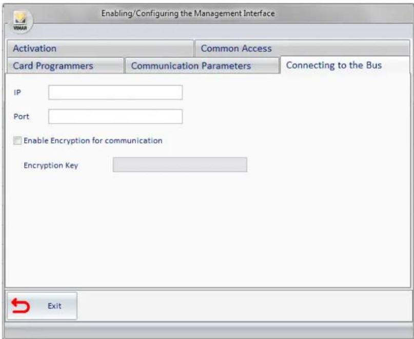
Picture 6 - Component for entering the Bus Connection parameters
In this section you should define the bus connection parameters, or the communication parameters of the Falcon Gateway service; such data can be viewed using the Gateway Configurator installed with the software. Picture 7 displays a proper configuration.

Picture 7 - Component for entering the compiled bus connection parameters
Micros-Fidelio Management Software
Introduction
The software for interfacing with management systems is compatible with version 2.20 of the FIAS protocol developed for "Micros - Fidelio".
Selecting and configuring the PMS
From the multiple choice, select the administrative management system used (Micros - Fidelio), after which more options will be available for entering the configuration information related to the selected system. The options are the following:
- Communication Parameters;
- Card Programmers;
- Common Access;
The following paragraphs explain how to configure the parameters listed above. In Picture 8 Micros - Fidelio was selected.
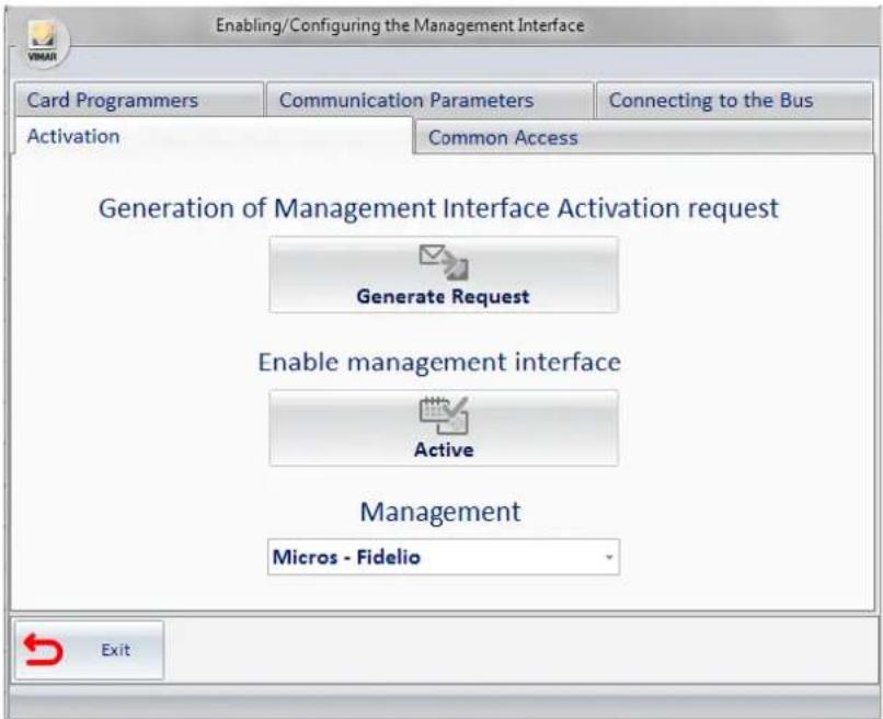
Picture 8 - Activation / Configuration Window Micros - Fidelio selected
Specifying the Communication Parameters
Selecting Communication Parameters, you will see what shown in Picture 9.

Picture 9 - Component for entering the Communication parameters
Enter the required data; in "Micros - Fidelio" the communication takes place via a network service; therefore, the address of the machine where "Micros - Fidelio (IP of the management system) is installed, as well as the related communication port (port of the management system) are required. Picture 10 is an example of a good configuration in which the machine where "Micros - Fidelio" is installed is the same as where the WCS is installed.

Picture 10 - Component for entering the compiled Communication parameters
Specifying Card Programmers parameters
You must enter all the programmers you want to use with "Micros - Fidelio". After specifying the reference to the card programmers which are present, through the interface given by the "Micros - Fidelio" system go to the WCS system configuration, as detailed below.
Selecting Card Programmer, you will see what shown in Picture 11.

Picture 11 - Component for entering the Card Programmers' data
Selecting the Add Programmer button, you will see a new row in the table as shown in Picture 12.

Picture 12 - Component for entering the Card Programmers with new programmer's line
- In the IP column, enter the address of the machine to which the card programmer is connected;
- In the Port column, enter the port used by the programmer (typically 8001);
- Select Use Encryption if you're actually using the encryption and when prompted (see Picture 13) enter the encryption key;

Picture 13 - Window for entering card programmer's encryption key
- In the Management Programmer column enter the encoding used on "Micros - Fidelio" to identify the particular program (typical values are '01', '02', etc...); If there are other programmers repeat the procedure for all those present.

Picture 14 - Component for entering the programmers' data completed
Specify the Common Access
All common accesses provided for "Micros-Fidelio" should be inserted. After specifying the references to the present common access through the Micros-Fidelio system interface, you can configure the WCS system as follows.
Selecting Common Access, you will see what shown in picture 15.

Picture 15 - Component for entering the Common Access
Selecting the Add Access button:
- a window appears (see picture 16) for requesting the Environment Number, this field must be filled with the Environment Number of and environment configured as "Common Access/Environment" (see the chapter ETS Configuration in the user manual of the WCS software);

Picture 16 - Window for entering the number of the common access as defined in the ETS Configuration
- by confirming the entered data another window will open (see Picture 17) to insert the Management Access, this field must be filled with the label used by the management software to identify the same common access (for "Micros - Fidelio" enter numbers 1, 2, 3, ..., 20 nothing else.)
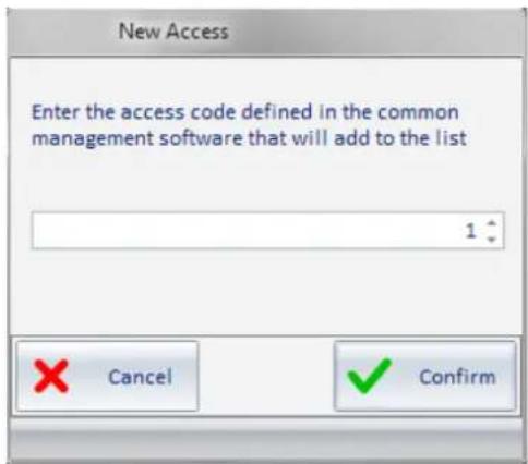
Picture 17 - Window for entering the code of the common access defined in the PMS
- If you check the Default column, it means that the request from Micros-Fidelio to create a new key, unless otherwise specified, must also enable access to this "environment";
- the description field is automatically entered (see Picture 18).
For each common access provided by the system the procedure described so far must be repeated.
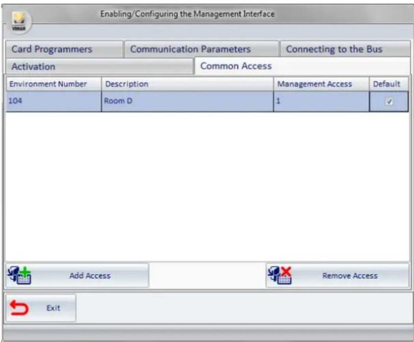
Picture 18 - Component for entering the Common Access successful
Ni.Ce. Informatica Management Software - Hotel2000
Introduction
The software interfacing with the management systems is compatible with the administration software Hotel2000 by Ni.Ce. Informatica.
Selecting and configuring the PMS
From the multiple choice, select the administrative management system used (NI.CE. Informatica – Hotel2000); after which more options will be available for entering the configuration information related to the selected system. The options are the following:
- Communication Parameters;
- Card Programmers;
- Common Access;
The following paragraphs explain how to configure the parameters listed above. In Picture 19 "NI.CE. Informatica – Hotel2000 was selected.
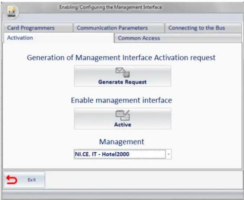
Picture 19 - Activation / Configuration Window if NI.CE. Informatica - Hotel2000 is selected
Specifying the Communication Parameters
Selecting Communication Parameters, you will see what shown in Picture 20.

Picture 20 - Component for entering the Communication parameters
Enter the requested data in "NI.CE. Informatica – Hotel2000"; the communication takes place through the exchange of text files. You must specify the folder where the files for the communication will be present.
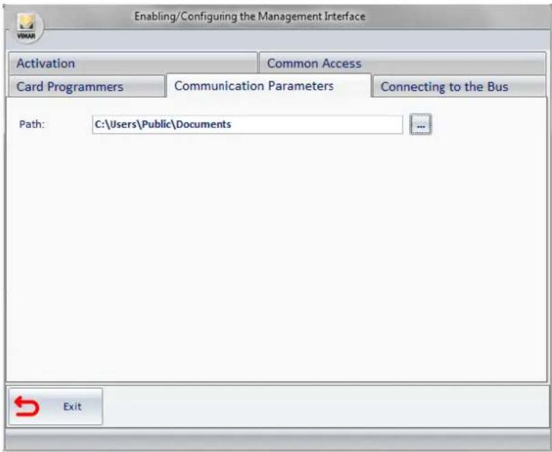
Picture 21 - Component for entering the compiled Communication parameters
Specifying Card Programmers parameters
You must enter all the programmers you want to use with "NI.CE. Informatica – Hotel2000". After specifying the reference to the card programmers which are present, through the interface given by the "NI.CE. Informatica – Hotel2000" system go to the CS system configuration, as detailed below. Selecting Card Programmer, you will see what shown in picture 22.
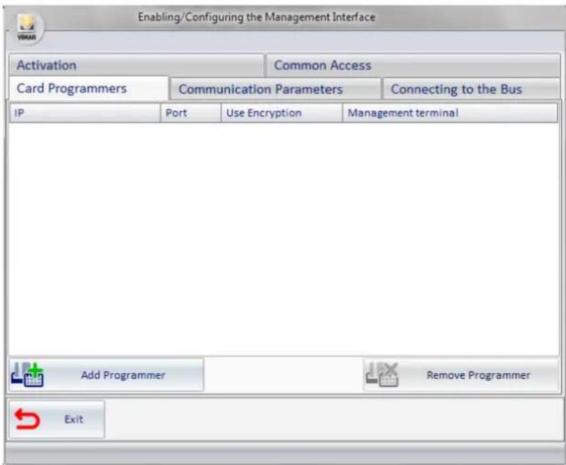
Picture 22 - Component for entering the Card Programmers' data
selecting the Add Programmer button, you will see a new row in the table as shown in Picture 23.

Picture 23 - Component for entering the Card Programmers with new programmer's line
- In the IP column, enter the address of the machine to which the card programmer is connected;
- In the Port column, enter the port used by the programmer (typically 8001);
- Select Use Encryption if you're actually using the encryption and when prompted (see Picture 24) enter the encryption key;
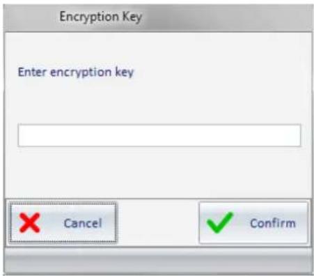
Picture 24 - Window for entering card programmer's encryption key
- In the Management Programmer column enter the encoding used on the "NI.CE. Informatica – Hotel2000" system to identify the particular programmer. If there are other programmers repeat the procedure for all those present.

Picture 25 - Component for entering the programmers' data completed
Specify the Common Access
All common accesses provided for "NI.CE. Informatica – Hotel2000" should be inserted. After specifying, through the interface given by the NI.CE. Informatica – Hotel2000 system, the references to the present common access, you can configure the WCS system as follows.
Selecting "Common Access", you will see what shown in picture 26.
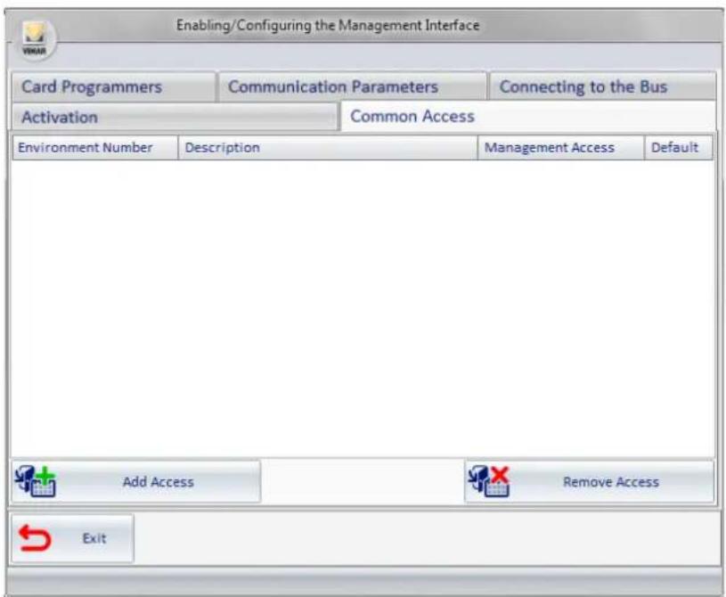
Picture 26 - Component for entering the Common Access
Selecting the Add Access button:
- a window appears (see picture 27) for requesting the Environment Number, this field must be filled with the Environment Number of and environment configured as "Common Access/Environment" (see the chapter ETS Configuration in the manual of the WCS software);

Picture 27 - Window for entering the number of the common access as defined in the ETS Configuration
- by confirming the entered data another window will open (see Picture 17) to insert the Management Access; this field must be filled with the label used by the management software to identify the same common access (for "NI.CE. Informatica - Hotel2000" enter the numbers 1, 2, 3, ..., 30 nothing else.)

Picture 28 - Window for entering the code of the common access defined in the PMS
- Enabling the check of the Default column means that the request from "NI.CE. Informatica - Hotel2000" to create a new key, unless otherwise specified, must also grant access to this "environment";
- The description field is automatically entered (see Picture 29).
For each common access provided by the system the procedure described so far must be repeated.

Picture 29 - Component for entering the Common Access successful
Hotel Management Software - Leonardo
Introduction
The software interfacing with the management systems is compatible with the Hotel's management software Leonardo.
Selecting and configuring the PMS
From the multiple choice, select the administrative management system used (Hotel Management - Leonardo), after which more options will be available for entering the configuration information related to the selected system. The options are the following:
- Communication Parameters;
- Card Programmers;
- Common Access;
The following paragraphs explain how to configure the parameters listed above. In Picture 30 "Hotel Management - Leonardo" was selected.
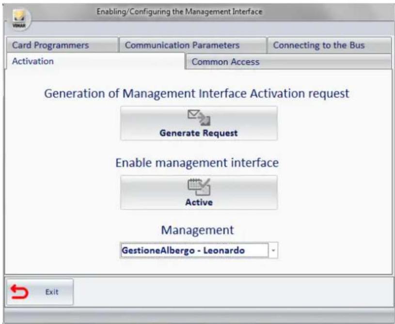
Figura 30 - Activation / Configuration Window, Hotel Management - Leonardo selected
Specifying the Communication Parameters
Selecting Communication Parameters, you will see what shown in Picture 31.

Picture 31 - Component for entering the Communication parameters
Enter the required data, in "Hotel Management - Leonardo" the communication takes place through files exchange; therefore, the path and name of the two files that are used for communication are needed. Picture 21 is an example of a valid configuration.

Picture 32 - Component for entering the compiled Communication parameters
Specifying Card Programmers parameters
You must enter all the programmers you want to use with "Hotel Management - Leonardo". After specifying the reference to the card programmers which are present, through the interface given by the "Hotel Management - Leonardo" system go to the WCS system configuration, as detailed below. Selecting Card Programmer, you will see what shown in picture 33.

Picture 33 - Component for entering the Card Programmers' data
selecting the Add Programmer button, you will see a new row in the table as shown in Picture 34.

Picture 34 - Component for entering the Card Programmers with new programmer's line
- In the IP column, enter the address of the machine to which the card programmer is connected;
- In the Port column, enter the port used by the programmer (typically 8001);
- Select Use Encryption if you're actually using the encryption and when prompted (see Picture 35) enter the encryption key;

Picture 35 - Window for entering card programmer's encryption key
- In the Management Terminal column enter the encoding used on "Hotel Management - Leonardo" to identify the particular programmer. If there are other management terminals, repeat the procedure for all those present.

Picture 36 - Component for entering the programmers' data completed
Specify the Common Access
All common accesses provided for the system should be inserted. "Hotel Management - Leonardo" specifies the behavior with a maximum of 5 common accesses for the card that is being created. On this screen you can define the default behavior that will be implemented.
Selecting Common Access, you will see what shown in picture 37.
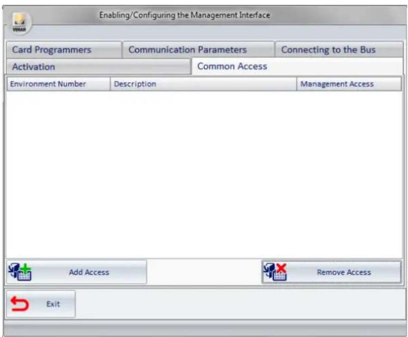
Picture 37 - Component for entering the Common Access
Selecting the Add Access button:
- a window appears (see picture 38) for requesting the Environment Number, this field must be filled with the Environment Number of and environment configured as "Common Access/Environment" (see the chapter ETS Configuration in the user manual of the WCS software);

Picture 38 - Window for entering the number of the common access as defined in the ETS Configuration
- by confirming the entered data another window will open (see Picture 39) to insert the Management Access; this field must be filled with the label used by the management software to identify the same common access. Please note that the field must be composed of 8 characters maximum (sample values: swimming pool, sauna, garage ...);
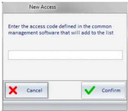
Picture 39 - Window for entering the code of the common access defined in the PMS
- The Description field is automatically entered (see Picture 40).
For each common access provided by the system the procedure described so far must be repeated.
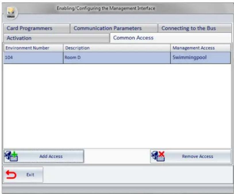
Picture 40 - Component for entering the Common Access successful
Other PMS adopting the WCS Protocol
Introduction
The software interfacing with management systems also provides a specification for communicating with the PMSs.
Selecting and configuring the PMS
From the multiple choice, select the WCS Protocol, after which more tabs will be available for entering the configuration information related to the selected system. The tabs are the following:
• Communication Parameters;
- Card Programmers;
- Common Access;
The following paragraphs explain how to configure the parameters listed above. In Picture 19 WCS Protocol was selected

Picture 41 - Activation / Configuration Window, WCS Protocol selected
Specifying the Communication Parameters
Selecting Communication Parameters, you will see what shown in Picture 42.
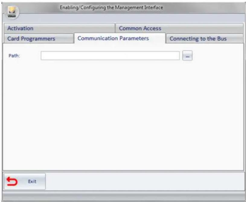
Picture 42 - Component for entering the Communication parameters
Enter the requested data, with the WCS Protocol; the communication takes place through the exchange of text files. You must specify the folder where the files for the communication will be present.
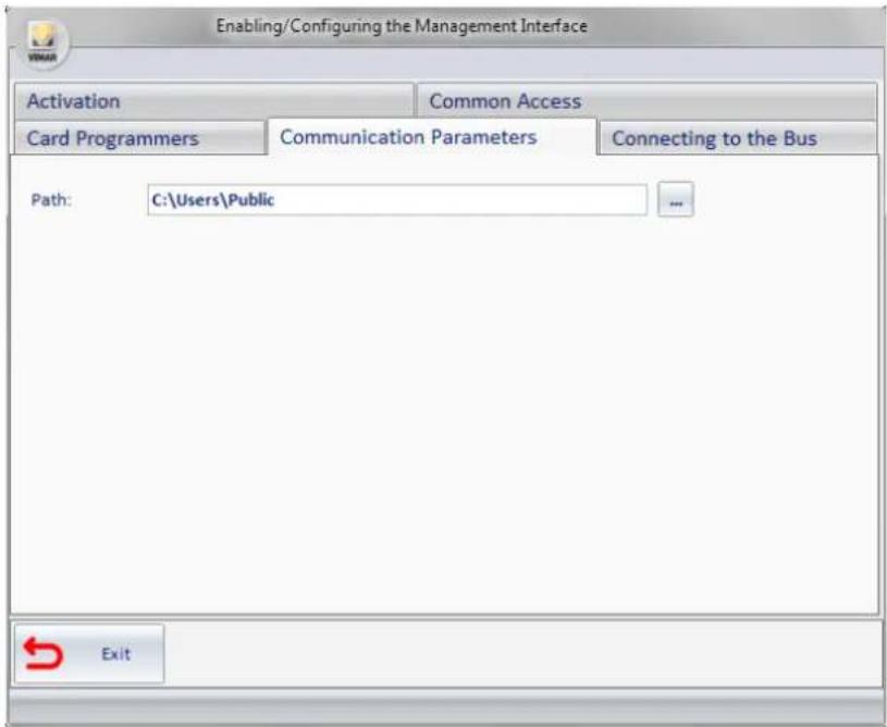
Picture 43 - Component for entering the Card Programmers' data
Specifying Card Programmers parameters
You must enter all the programmers you want to use for interfacing. After specifying the reference to the card programmers which are present, through the interface given by the system go to the WCS system configuration, as detailed below.
Selecting Card Programmer, you will see what shown in Picture 44.

Picture 44 - Component for entering the Card Programmers' data
Selecting the Add Programmer button, you will see a new row in the table as shown in Picture 45.

Picture 45 - Component for entering the Card Programmers with new programmer's line
- In the IP column, enter the address of the machine to which the card programmer is connected;
- In the Port column, enter the port used by the programmer (typically 8001);
- Select Use Encryption if you're actually using the encryption and when prompted (see Picture 46) enter the encryption key;

Picture 46 - Window for entering card programmer's encryption key
- In the Management Programmer column enter the encoding used on PMS to identify the particular programmer. If there are other programmers repeat the procedure for all those present.

Picture 47 - Component for entering the Card Programmers with new programmer's line
Specify the Common Access
You must enter all the programmers you want to use for interfacing.
After specifying the reference to the card programmers which are present, through the interface given by the system go to the WCS system configuration, as detailed below.
Selecting Card Programmer, you will see what shown in Picture 48.

Picture 48 - Component for entering the Common Access
Selecting the Add Access button:
- a window appears (see picture 49) for requesting the Environment Number, this field must be filled with the Environment Number of and environment configured as "Common Access/Environment" (see the chapter ETS Configuration in the manual of the WCS software);

Picture 49 - Window for entering the number of the common access as defined in the ETS Configuration
- by confirming the entered data another window will open (see Picture 50) to insert the Management Access; this field must be filled with the label used by the management software to identify the same common access (enter the numbers 1, 2, 3, ..., 30 nothing else);

Picture 50 - Window for entering the code of the common access defined in the PMS
- If you check the Default column, it means that the request from PMS to create a new key, unless otherwise specified, must also enable access to this "environment";
- the description field is automatically entered (see Picture 51). For each common access provided by the system the procedure described so far must be repeated.

Picture 51 - Component for entering the Common Access successful
USE SECTION
Software start up
The software to interface with management systems is a Windows service that starts automatically with the PC, if the license has been activated. This service does not provide user interface. To start or stop its execution, proceed as for any other Windows service, making sure the name of this service is Vimar WCS To PMS Interface Service.
Micros-Fidelio Management
Introduction
The presence of the interfacing software allows the transparent transition of the data operator from the Administrative Management system to the Well-Contact Suite System. The transferred data is the main data provided for the guest and the main data relevant to the reservation.
Exchanged data
As regards the guests' personal data, Micros-Fidelio provides the exchange of:
- Name;
- Last name;
• Title (Mr, Mrs, etc...).
As far as the reservation, the following exchange of data is provided:
- Check-in time;
- Check-out time;
• Master bedroom number, and any other rooms involved; - Reservation Code.
In addition, the PMS here described allows the exchange of other information, necessary for the creation and activation of the cards, such as:
• reference to the card programmer to use;
- any common access to be enabled and related policy;
- any other room numbers to be enabled.
Micros-Fidelio operations and effects on the WCS
| Leonardo Micros - Fidelio/ Opera | Operation the operator must perform on Vimar's Well Contact system | Consequence on the Well-Contact Suite |
| Check-in time of a client with simultaneous generation of the key. | Insert the card to be written in the proper programmer before clicking "OK" on Fidelio/Opera. Fidelio/Opera. | Creating reservation for a client |
| Writing and activation of the card | ||
| Client Check-Out - Res | ervation archiviation | |
| Removes access to the checked out room by all the cards of the reservation. | ||
| Creating a new key without checking in the client | Insert the card to be written in the proper programmer before clicking "OK" on Fidelio/Opera. | If the reservation is checked in, access to the room for any other existing cards is disabled.Writing and activation of the card, the card in the programmer is the only valid card. |
| If the reservation is not checked in, the card is written but not activated. The card will be activated when after the check-in. | ||
| Creation of a new duplicate key | Insert the card to be written in the proper programmer before clicking "OK" on Fidelio/Opera. | Adding a new card to those associated with the reservation |
| Writing and, if the reservation is checked in, simultaneous activation of the card. | ||
| Changing the details of the client. | - Name Last name and Salutation of the client are updated | |
| Changing the length of stay | - The arrival and departure dates are updated. | |
| Deleting the key without checking out the client | Insert the card to be deleted in the proper programmer. | If the card in the programmer is related to the specified reservation, such card is re-initialized with defaultvalues. |
| Key reading Insert the card to be read in the proper programmer before clicking "OK" on Fidelio/Opera. | - | |
| Switching room Insert the card to be written in the proper programmer before clicking "OK".If the request does not appear, the original key remains valid. | The reservation will be relocated in the new room. | |
| The previously involved cards are deleted. The card in the programmer will be the only valid card for the new room. To obtain an additional card, follow the steps to create a duplicate key. | ||
Ni.Ce. Informatica Management Software - Hotel2000
Introduction
The presence of the interfacing software allows the transparent transition of the data operator from the Administrative Management system to the Well-Contact Suite System. The transferred data is the main data provided for the guest and the main data relevant to the reservation.
Exchanged data
As regards the guests' personal data, the Ni.Ce. Informatica – Hotel2000 system provides the exchange of:
- Name,
- Last name,
• City,
• Salutation (Mr, Mrs, etc...).
As far as the reservation, the following exchange of data is provided
- Check-in time,
- Check-out time,
- Room number.
In addition, the PMS here described allows the exchange of other information, necessary for the creation and activation of the cards, such as:
• reference to the card programmer to use,
- any common access to be enabled and related policy,
Ni.Ce. Informatica Operations - Hotel2000 operations and effects on the WCS
| Ni.Ce.Informatica- Hotel2000Operation | Operation the operator must perform on Vimar's Well Contact system | Consequence on the Well-Contact Suite |
| Check-in time of a client with simultaneous generation of the key. | Insert the card to be written in the proper programmer before clicking "OK" on Hotel2000. | Creating reservation for a client |
| Writing and activation of the card | ||
| Client Check-Out - Reservation archiviation | ||
| Removes access to the checked out room by all the cards of the reservation. | ||
| Creation of a new key | Insert the card to be written in the proper programmer before clicking "OK" on Hotel2000. | If the reservation is checked in, writing and activation of the card. |
| If the reservation is not checked in, the card is written but not activated. The card will be activated when after the check-in. | ||
| Changing the details of the client. | - Name, last name, city and salutation of the client are updated | |
| Changing the length of stay | - The arrival and departure dates are updated. | |
| Erasing specific card key | - Access is disabled for the specified card. | |
| Deletion of card in a programmer | Insert the card to be deleted in the proper programmer. | If the card in the programmer is related to the specified reservation, such card is re-initialized with defaultvalues. |
| Key reading Insert the card to be read in the proper programmer before clicking "OK" on Hotel2000. | - | |
| Switching room Insert the card to be written in the proper programmer before clicking "OK". | The reservation will be relocated in the new room. | |
| The previously involved cards are deleted. The card in the programmer will be the only valid card for the new room. To obtain an additional card, follow the steps to create a duplicate key. | ||
Hotel Management Software - Leonardo
Introduction
The presence of the interfacing software allows the transparent transition of the data operator from the Administrative Management system to the Well-Contact Suite System. The transferred data is the main data provided for the guest and the main data relevant to the reservation.
Exchanged data
As regards the guests' personal data, Leonardo provides the exchange of:
- Last name (always present),
- Name (if not specified),
• Home address and other contact details (if not specified),
As far as the reservation, the following exchange of data is provided
- Main Room Number (always present),
- Check-in time (always present),
- Check-out time (always present),
In addition, the PMS here described allows the exchange of other information, necessary for the creation and activation of the cards, such as:
• reference to the card programmer to use,
- any common access to be enabled and related policy.
Hotel Management - Leonardo operations and effects on the WCS
| Leonardo Operation | Operation the operator must perform on Vimar's Well Contact system | Consequence on the Well-Contact Suite |
| Check-in time of a client with simultaneous generation of the key. | Insert the card to be written in the proper programmer when prompted by Leonardo | If not previously created with the appropriate command, a reservation for the client is created. |
| Writing and activation of the card. | ||
| Room Check-Out | - Removes access to the check | ed out room by all the cards of the reservation. |
| Reservation archiviation | ||
| Creating room reservation for a client | - Creating reservation for a client | |
| Deleting room reservation for a client | - Removes access to the room | by all the cards of the reservation. |
| Reservation archiviation | ||
Other PMS adopting the WCS Protocol
Introduction
The presence of the interfacing software allows the transparent transition of the data operator from the Administrative Management system to the Well-Contact Suite System. The transferred data is the main data provided for the guest and the main data relevant to the reservation.
Exchanged data
As regards the guests' personal data, the WCS Protocol provides the exchange of:
- Name,
- Last name,
• City,
- Title (Mr, Mrs, etc...).
As far as the reservation, the following exchange of data is provided
- Check-in time,
- Check-out time,
- Room number.
In addition, the PMS here described allows the exchange of other information, necessary for the creation and activation of the cards, such as:
• reference to the card programmer to use,
- any common access to be enabled and related policy,
Used PMS operations and effects on the WCS
| Used PMSOperation | Operation the operator must perform on Vimar's Well Contact system | Consequence on the Well-Contact Suite |
| Check-in time of a client with simultaneous generation of the key. | Insert the card to be written in the proper programmer before clicking "OK" on PMS. | Creating reservation for a client |
| Writing and activation of the card | ||
| Client Check-Out - Reservation archiviation | ||
| Removes access to the checked out room by all the cards of the reservation. | ||
| Creation of a new key Insert the card to be written in the proper programmer before clicking "OK" on PMS. | If the reservation is checked in, writing and activation of the card | |
| If the reservation is not checked in, the card is written but not activated. The card will be activated when after the check-in. | ||
| Changing the details of the client. | - Name, last name, city and salutation of the client are updated | |
| Changing the length of stay | - The arrival and departure dates are updated. | |
| Erasing specific card key | - Access is disabled for the specified card. | |
| Deletion of card in a programmer | Insert the card to be deleted in the proper programmer. | If the card in the programmer is related to the specified reservation, such card is re-initialized with default values . |
| Key reading Insert the card to be written in the proper programmer before starting the procedure | - | |
| Switching room Insert the card to be written in the proper programmer before clicking "OK". | The reservation will be relocated in the new room. | |
| The previously involved cards are deleted. The card in the programmer will be the only valid card for the new room. To obtain an additional card, follow the steps to create a duplicate key. | ||
- Software for interfacing with management systems
- Vimar end-user license contract
- VIMAR SPA
- INDEX
- DESCRIPTION OF THE SOFTWARE FOR INTERFACING WITH MANAGEMENT SYSTEMS (ART. 01595) 2
- INSTALLATION 3
- CONFIGURATION 5
- USE 33
- Description of the software for interfacing with management systems (art. 01595)
- IMPORTANT:
- Operations
- Other Characteristics
- How to install the software
- Software update
- Introduction
- Configuration of the interfacing with management software
- License Activation
- Selecting and configuring the administrative management system
- Micros-Fidelio Management Software
- Selecting and configuring the PMS
- Specifying Card Programmers parameters
- Specify the Common Access
- Selecting the Add Access button:
- Ni.Ce. Informatica Management Software - Hotel2000
- Hotel Management Software - Leonardo
- Other PMS adopting the WCS Protocol
- Specifying the Communication Parameters
- Software start up
- Micros-Fidelio Management
- Exchanged data
- Used PMS operations and effects on the WCS
Brand : Vimar
Model : 01595
Category : Software