
Flowclear 58748 - Heating BESTWAY - Free user manual and instructions
Find the device manual for free Flowclear 58748 BESTWAY in PDF.

| Product type | Pool heater (heat pump) |
| Brand | Bestway |
| Model | Flowclear 58748 |
| Heating capacity | 4.4 kW |
| Power supply | 220-240 V~50 Hz, 5.33 A |
| Power consumption | 0.92 kW |
| COP | 4.8 |
| Protection rating | IPX5 |
| Refrigerant | R32 (0.35 kg) |
| Recommended water flow rate | ≥2.0 m³/h |
| Recommended pool volume | ≤30 m³ |
| Pipe connection | 32 or 38 mm |
| Heat exchanger | Titanium |
| Air flow direction | Horizontal |
| Working ambient temperature | 12°C to 43°C |
| Heating rate | 1°C to 3°C/24 h |
| Adjustable temperature range | 15°C to 40°C |
| Fuse | T, 250 V, 3.15 A |
| Water pressure max/min | 1 MPa / 0.01 MPa |
| Working water temperature | 5°C to 40°C |
| Dimensions (approx.) | 440 x 363 x 437 mm |
| Safety | Residual current device (RCD) 30 mA, distance 2 m from the pool |
| Maintenance | Clean casing and grille with damp cloth, drain in winter |
| Warranty | See www.bestwaycorp.com |
Frequently Asked Questions - Flowclear 58748 BESTWAY
User questions about Flowclear 58748 BESTWAY
0 question about this device. Answer the ones you know or ask your own.
Ask a new question about this device
Download the instructions for your Heating in PDF format for free! Find your manual Flowclear 58748 - BESTWAY and take your electronic device back in hand. On this page are published all the documents necessary for the use of your device. Flowclear 58748 by BESTWAY.
USER MANUAL Flowclear 58748 BESTWAY
text_image
bestwaycorp.com/support58748
OWNER'S MANUAL
bestwaycorp.com/support
Visit the Bestway YouTube channel YouTube

text_image
Visit www.bestwaycorp.com/support for help WE SUGGEST NOT TO RETURN THE PRODUCT TO THE STORE QUESTIONS? PROBLEMS? MISSING PARTS? For FAQ, Manuals, Videos Or Spare Parts, Please Visit bestwaycorp.com/supportOWNER'S MANUAL
58748 4kW Pool Heater

Visit the Bestway YouTube channel
IMPORTANT SAFETY INSTRUCTIONS
WARNING
220-240V\~50Hz, 1PH, 5.33A, 1200W, IPX5
At 26°C Air and 26°C Water Condition:
Heating Capacity: 4.4kW
Power Input: 0.92kW
COP: 4.8
Noise Level 1M: 55dB(A)
Max. Suction Pressure: 2.5MPa
Max. Discharge Pressure: 4.2MPa
Max. Allowable Pressure: 4.4MPa
Refrigerant: R32(0.35kg)
GWP: 675
CO _2 Equivalent: 0.236T
If the supply cord is damaged, it must be replaced by the manufacturer, its service agent or similarly qualified persons in order to avoid a hazard.
This appliance can be used by children aged from 8 years and above and persons with reduced physical, sensory or mental capabilities or lack of experience and knowledge if they have been given supervision or instruction concerning use of the appliance in a safe way and understand the hazards involved. Children shall not play with the appliance. Cleaning and user maintenance shall not be made by children without supervision.
The appliance shall be placed 2m away from the pool.
The appliance cannot be using while people are inside the pool.
The appliance is to be supplied by an isolating transformer or supplied through a residual current device (RCD) having a rated residual operating current not exceeding 30 mA.
Extension cords can't be used.
If instruction is missed, please contact with Bestway or search it in website: www.bestwaycorp.com.
CAUTION: Ensure all installation or service work is only carried out by licensed personnel. Hermetically sealed equipment, leakage tested, contains fluorinated Greenhouse gas.
The appliance shall be installed in accordance with national wiring regulations.
Do not use means to accelerate the defrosting process or to clean, other than those recommended by the manufacturer.
The appliance shall be stored in a room without continuously operating ignition sources (for example: open flames, an operating gas appliance or an operating electric heater.
Do not pierce or burn.
Be aware that refrigerants may not contain an odour.
Compliance with national gas regulations shall be observed.
Keep ventilation openings clear of obstruction;
Servicing shall be performed only as recommended by the manufacturer.
The appliance shall be stored in a well-ventilated area.
The appliance shall be stored in a room without continuously operating open flames (for example an operating gas appliance) and ignition sources (for example an operating electric heater)
The appliance shall be stored so as to prevent mechanical damage from occurring.
Any person who is involved with working on or breaking into a refrigerant circuit should hold a current valid certificate from an industry-accredited assessment authority, which authorises their competence to handle refrigerants safely in accordance with an industry recognised assessment specification.
Servicing shall only be performed as recommended by the equipment manufacturer. Maintenance and repair requiring the assistance
of other skilled personnel shall be carried out under the supervision of the person competent in the use of flammable refrigerants.
Information on servicing
Checks to the area
Prior to beginning work on systems containing flammable refrigerants, safety checks are necessary to ensure that the risk of ignition is minimised. For repair to the refrigerating system, the following precautions shall be complied with prior to conducting work on the system.
Work procedure
Work shall be undertaken under a controlled procedure so as to minimise the risk of a flammable gas or vapour being present while the work is being performed.
General work area
All maintenance staff and others working in the local area shall be instructed on the nature of work being carried out. Work in confined spaces shall be avoided. The area around the workspace shall be sectioned off. Ensure that the conditions within the area have been made safe by control of flammable material.
Checking for presence of refrigerant
The area shall be checked with an appropriate refrigerant detector prior to and during work, to ensure the technician is aware of potentially flammable atmospheres. Ensure that the leak detection equipment being used is suitable for use with flammable refrigerants, i.e. non-sparking, adequately sealed or intrinsically safe.
Presence of fire extinguisher
If any hot work is to be conducted on the refrigeration equipment or any associated parts, appropriate fire extinguishing equipment shall be available to hand. Have a dry powder or CO_2 fire extinguisher adjacent to the charging area.
No ignition sources
No person carrying out work in relation to a refrigeration system which involves exposing any pipe work that contains or has contained flammable refrigerant shall use any sources of ignition in such a manner that it may lead to the risk of fire or explosion. All possible ignition sources, including cigarette smoking, should be kept sufficiently far away from the site of installation, repairing, removing and disposal, during which flammable refrigerant can possibly be released to the surrounding space. Prior to work taking place, the area around the equipment is to be surveyed to make sure that there are no flammable hazards or ignition risks. "No Smoking" signs shall be displayed.
Ventilated area
Ensure that the area is in the open or that it is adequately ventilated before breaking into the system or conducting any hot work. A degree of ventilation shall continue during the period that the work is carried out. The ventilation should safely disperse any released refrigerant and preferably expel it externally into the atmosphere.
Checks to the refrigeration equipment
Where electrical components are being changed, they shall be fit for the purpose and to the correct specification. At all times the manufacturer's maintenance and service guidelines shall be followed. If in doubt consult the manufacturer's technical department for assistance.
The following checks shall be applied to installations using flammable refrigerants:
- the ventilation machinery and outlets are operating adequately and are not obstructed;
- if an indirect refrigerating circuit is being used, the secondary circuit shall be checked for the presence of refrigerant;
- marking to the equipment continues to be visible and legible. Markings and signs that are illegible shall be corrected;
- refrigeration pipe or components are installed in a position where they are unlikely to be exposed to any substance which may corrode refrigerant containing components, unless the components are constructed of materials which are inherently resistant to being corroded or are suitably protected against being so corroded.
Checks to electrical devices
Repair and maintenance to electrical components shall include initial safety checks and component inspection procedures. If a fault exists that could compromise safety, then no electrical supply shall be connected to the circuit until it is satisfactorily dealt with. If the fault cannot be corrected immediately but it is necessary to continue operation, an adequate temporary solution shall be used. This shall be reported to the owner of the equipment so all parties are advised.
Initial safety checks shall include:
- that capacitors are discharged: this shall be done in a safe manner to avoid possibility of sparking;
- that no live electrical components and wiring are exposed while charging, recovering or purging the system;
- that there is continuity of earth bonding.
Repairs to sealed components
During repairs to sealed components, all electrical supplies shall be disconnected from the equipment being worked upon prior to any removal of sealed covers, etc. If it is absolutely necessary to have an electrical supply to equipment during servicing, then a permanently operating form of leak detection shall be located at the most critical point to warn of a potentially hazardous situation.
Particular attention shall be paid to the following to ensure that by working on electrical components, the casing is not altered in such a way that the level of protection is affected. This shall include damage to cables, excessive number of connections, terminals not made to original specification, damage to seals, incorrect fitting of glands, etc.
Ensure that apparatus is mounted securely.
Ensure that seals or sealing materials have not degraded such that they no longer serve the purpose of preventing the ingress of flammable atmospheres. Replacement parts shall be in accordance with the manufacturer's specifications.
NOTE: The use of silicon sealant may inhibit the effectiveness of some types of leak detection equipment. Intrinsically safe components do not have to be isolated prior to working on them.
Repair to intrinsically safe components
Do not apply any permanent inductive or capacitance loads to the circuit without ensuring that this will not exceed the permissible voltage and current permitted for the equipment in use.
Intrinsically safe components are the only types that can be worked on while live in the presence of a flammable atmosphere.
The test apparatus shall be at the correct rating.
Replace components only with parts specified by the manufacturer. Other parts may result in the ignition of refrigerant in the atmosphere from a leak.
Cabling
Check that cabling will not be subject to wear, corrosion, excessive pressure, vibration, sharp edges or any other adverse environmental effects. The check shall also take into account the effects of ageing or continual vibration from sources such as compressors or fans.
Detection of flammable refrigerants
Under no circumstances shall potential sources of ignition be used in the searching for or detection of refrigerant leaks. A halide torch (or any other detector using a naked flame) shall not be used.
Leak detection methods
The following leak detection methods are deemed acceptable for systems containing flammable refrigerants.
Electronic leak detectors shall be used to detect flammable refrigerants, but the sensitivity may not be adequate, or may need re-calibration. (Detection equipment shall be calibrated in a refrigerant-free area.) Ensure that the detector is not a potential source of ignition and is suitable for the refrigerant used. Leak detection equipment shall be set at a percentage of the LFL of the refrigerant and shall be calibrated to the refrigerant employed and the appropriate percentage of gas (25% maximum) is confirmed.
Leak detection fluids are suitable for use with most refrigerants but the use of detergents containing chlorine shall be avoided as the chlorine may react with the refrigerant and corrode the copper pipe-work.
If a leak is suspected, all naked flames shall be removed/extinguished.
If a leakage of refrigerant is found which requires brazing, all of the refrigerant shall be recovered from the system, or isolated (by means of shut off valves) in a part of the system remote from the leak. Oxygen free nitrogen (OFN) shall then be purged through the system both before and during the brazing process.
Removal and evacuation
When breaking into the refrigerant circuit to make repairs - or for any other purpose - conventional procedures shall be used. However, it is important that best practice is followed since flammability is a consideration. The following procedure shall be adhered to:
- remove refrigerant;
- purge the circuit with inert gas;
- evacuate;
- purge again with inert gas;
- open the circuit by cutting or brazing.
The refrigerant charge shall be recovered into the correct recovery cylinders. The system shall be "flushed" with OFN to render the unit safe. This process may need to be repeated several times. Compressed air or oxygen shall not be used for this task. Flushing shall be achieved by breaking the vacuum in the system with OFN and continuing to fill until the working pressure is achieved, then venting to atmosphere, and finally pulling down to a vacuum. This process shall be repeated until no refrigerant is within the system. When the final OFN charge is used, the system shall be vented down to atmospheric pressure to enable work to take place. This operation is absolutely vital if brazing operations on the pipe-work are to take place.
Ensure that the outlet for the vacuum pump is not close to any ignition sources and there is ventilation available.
Charging procedures
In addition to conventional charging procedures, the following requirements shall be followed.
- Ensure that contamination of different refrigerants does not occur when using charging equipment. Hoses or lines shall be as short as possible to minimise the amount of refrigerant contained in them.
- Cylinders shall be kept upright.
- Ensure that the refrigeration system is earthed prior to charging the system with refrigerant.
- Label the system when charging is complete (if not already).
- Extreme care shall be taken not to overfill the refrigeration system.
Prior to recharging the system it shall be pressure tested with OFN. The system shall be leak tested on completion of charging but prior to commissioning. A follow up leak test shall be carried out prior to leaving the site.
Decommissioning
Before carrying out this procedure, it is essential that the technician is completely familiar with the equipment and all its detail. It is recommended good practice that all refrigerants are recovered safely. Prior to the task being carried out, an oil and refrigerant sample shall be taken in case analysis is required prior to re-use of reclaimed refrigerant. It is essential that electrical power is available before the task is commenced.
a) Become familiar with the equipment and its operation.
b) Isolate system electrically.
c) Before attempting the procedure ensure that:
- mechanical handling equipment is available, if required, for handling refrigerant cylinders;
- all personal protective equipment is available and being used correctly;
- the recovery process is supervised at all times by a competent person;
- recovery equipment and cylinders conform to the appropriate standards.
d) Pump down refrigerant system, if possible.
e) If a vacuum is not possible, make a manifold so that refrigerant can be removed from various parts of the system.
f) Make sure that cylinder is situated on the scales before recovery takes place.
g) Start the recovery machine and operate in accordance with manufacturer's instructions.
h) Do not overfill cylinders. (No more than 80 % volume liquid charge).
i) Do not exceed the maximum working pressure of the cylinder, even temporarily.
j) When the cylinders have been filled correctly and the process completed, make sure that the cylinders and the equipment are removed from site promptly and all isolation valves on the equipment are closed off.
k) Recovered refrigerant shall not be charged into another refrigeration system unless it has been cleaned and checked.
Labelling
Equipment shall be labelled stating that it has been de-commissioned and emptied of refrigerant. The label shall be dated and signed. Ensure that there are labels on the equipment stating the equipment contains flammable refrigerant.
Recovery
When removing refrigerant from a system, either for servicing or decommissioning, it is recommended good practice that all refrigerants are removed safely.
When transferring refrigerant into cylinders, ensure that only appropriate refrigerant recovery cylinders are employed.
Ensure that the correct number of cylinders for holding the total system charge are available. All cylinders to be used are designated for the recovered refrigerant and labelled for that refrigerant (i.e. special cylinders for the recovery of refrigerant). Cylinders shall be complete with pressure relief valve and associated shut-off valves in good working order. Empty recovery cylinders are evacuated and, if possible, cooled before recovery occurs.
The recovery equipment shall be in good working order with a set of instructions concerning the equipment that is at hand and shall be suitable for the recovery of flammable refrigerants.
In addition, a set of calibrated weighing scales shall be available and in good working order.
Hoses shall be complete with leak-free disconnect couplings and in good condition. Before using the recovery machine, check that it is in satisfactory working order, has been properly maintained and that any associated electrical components are sealed to prevent ignition in the event of a refrigerant release. Consult manufacturer if in doubt.
The recovered refrigerant shall be returned to the refrigerant supplier in the correct recovery cylinder, and the relevant Waste Transfer Note arranged. Do not mix refrigerants in recovery units and especially not in cylinders.
If compressors or compressor oils are to be removed, ensure that they have been evacuated to an acceptable level to make certain that flammable refrigerant does not remain within the lubricant. The evacuation process shall be carried out prior to returning the compressor to the suppliers. Only electric heating to the compressor body shall be employed to accelerate this process. When oil is drained from a system, it shall be carried out safely.
DISPOSAL

Electrical products should not be disposed of with household waste. Please recycle where facilities exist. Check with your local authority or retailer for recycling advice.
The Pool Heater contains refrigerant. As it is a harmful substance, the refrigerant must be disposed of properly at a collection point approved for this purpose.
SETUP
CHECK LIST
To check the parts included in the box, consult the parts list in this manual. Verify that the equipment components represent the model that you had intended to purchase. In case of any damaged or missing parts at the time of purchase, visit our website bestwaycorp.com/support.
CHOOSE THE CORRECT LOCATION
The Pool Heater will work properly in any location under the following conditions:
- The Pool Heater must be located 2m away from the pool and 1m away from any objects.
- Always hold the Pool Heater upright. If the device has been held in a different position, to stabilize the liquid gas inside the system, wait at least 24 hours before starting to use it.
- Never install the unit closed to shrubbery that could block the air inlet. Such locations impair the continuous supply of fresh air, resulting in reduced efficiency and possibly preventing sufficient heat output.
- The Pool Heater has a fan to expel cold air. Make sure to position the Pool Heater so that the cold air will not go in the direction of the pool.
- Place the Pool Heater near a drain point. The air drawn into the Pool Heater is strongly cooled by the operation for heating the pool water, which may cause condensation on the evaporator.
The amount of condensation may be as much as several liters per hour at high relative humidity. This is sometimes mistakenly regarded as a water leak.
INSTALLATION
For the installation, follow the instructions in this manual. Drawings in the assembly section are for illustration purposes only and may not reflect actual product. Not to scale.
RECOMMENDATIONS DURING THE INSTALLATION
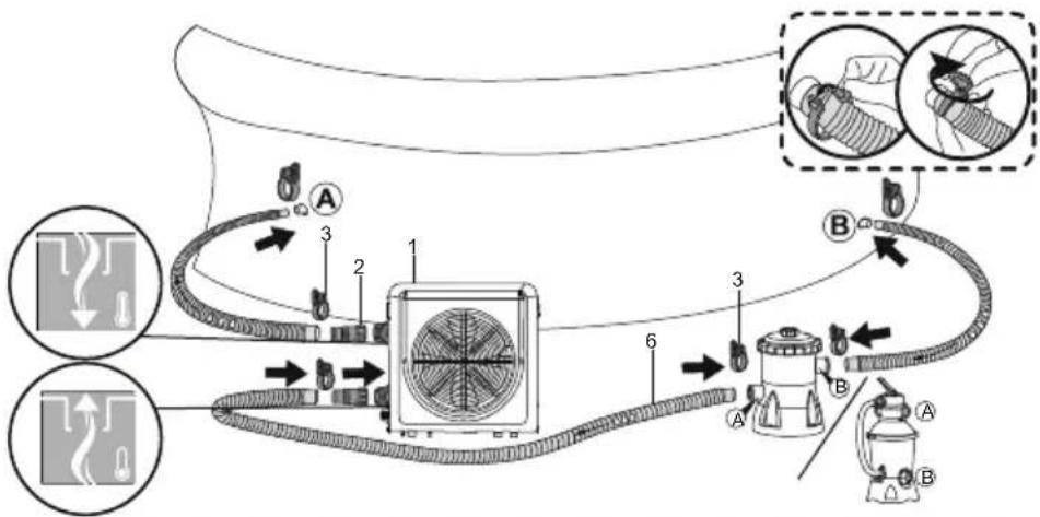
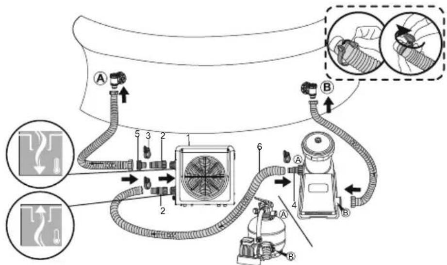
- In order to heat the water in the pool, the Filter Pump must be running to circulate the water through the Pool Heater. It will not start up if the water is not circulating.
- If a chlorinator or other equipment that produces chemicals is installed in the system, it must be installed after the Pool Heater. This will help avoid a high level of chemicals, which can damage the metal part of the Pool Heater.
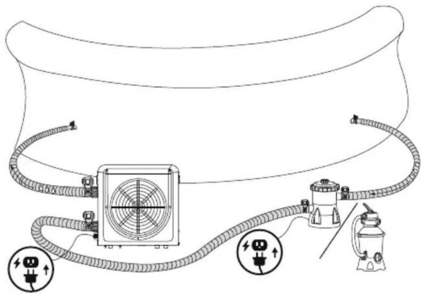
- Before connecting the unit, verify that the supply voltage matches the operating voltage of the Pool Heater.
- When connecting the plug to the wall socket, ensure the power plug is secure. If the plug is not secure, it may cause an electric shock, over-heating or fire.
- Never pull out the power plug during operation. Otherwise, it may cause an electric shock or a fire due to over-heating.
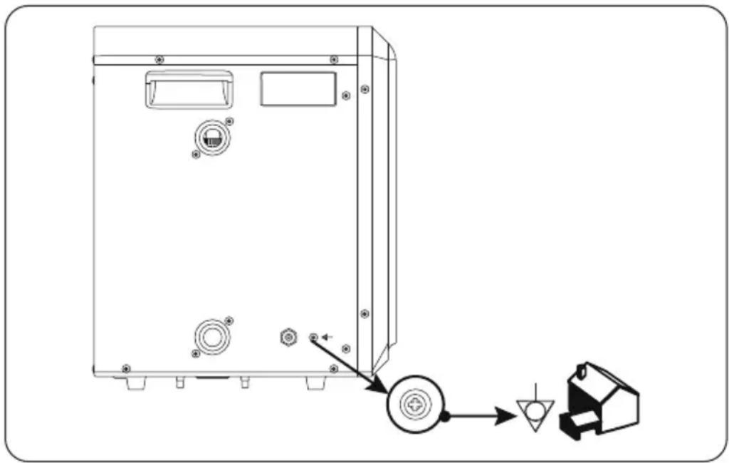
- Heat pump equipotential bonding terminal
It is recommended to arrange for a qualified electrician to connect the heat pump to an equipotential bonding terminal using a minimum 2.5mm^2 solid copper conductor.
natural_image
Technical line drawing of a device casing with mounting holes and a control panel connected to a motor (no text or symbols)USING THE POOL HEATER
- Switch on the filter pump. Check for leaks and verify that water is flowing from and to the swimming pool.
- Connect power to the heat pump and press the On/Off button on the control panel. The unit will start up.
- When first powered on, the Pool Heater will check the water flow in 30 seconds, then start running if the water flow is ok.
- The heat pump has a built-in, 3-minute start-up delay to protect the circuitry and avoid excessive contact wear. The unit will restart automatically after this time delay expires.
- After a few minutes, check whether the air blowing out of the unit is cooler.
- When turning off the filter pump, the unit should also turn off automatically.
- Depending on the initial temperature of the water in the swimming pool and the air temperature, it may take some time to heat the water to the desired temperature. A good swimming pool cover can dramatically reduce the required length of time.
text_image
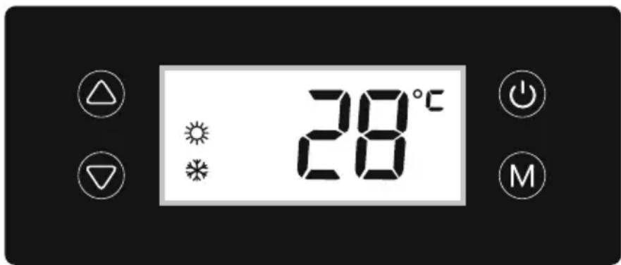
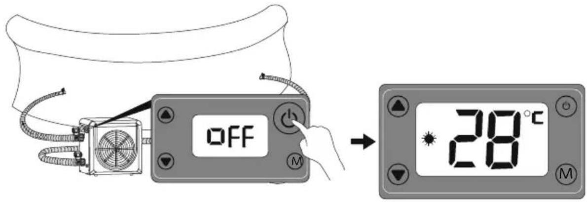
28°C MWhen the Pool Heater is running or on standby, the display shows the water inlet temperature.

HEATING LED: The icon is on when the Pool Heater is working

DEFROSTING LED: The icon flashes when the Pool Heater is defrosting

ON/OFF BUTTON: Press this button to turn on the heat pump. The LED display will show the water setting temperature for 3s, then it will show the real water temperature. Press the button again to turn off the Pool Heater, it will show 'OFF' on the display.


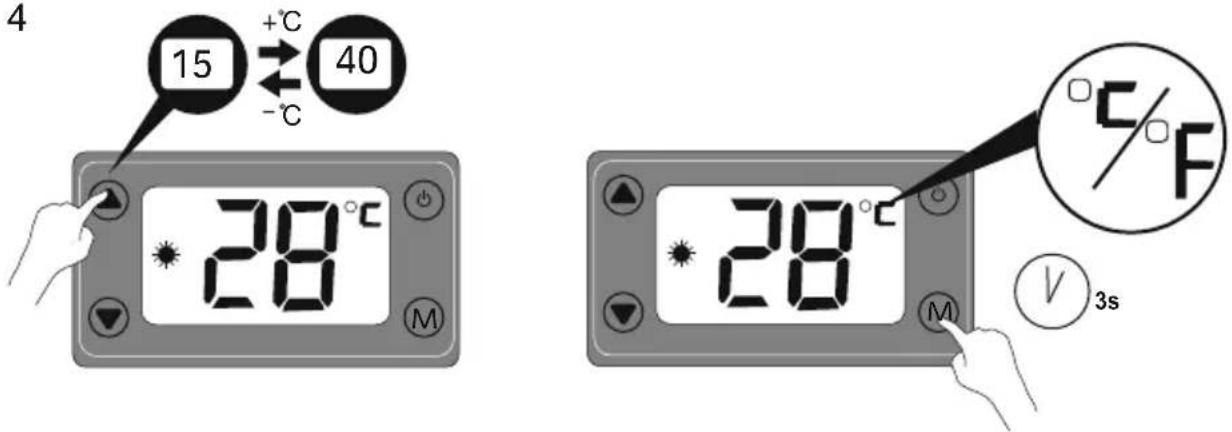
TEMPERATURE ADJUSTMENT BUTTON: Press the arrows adjust the desired water temperature. The temperature on the display will flash when the desired temperature is set and the data will be saved after 3 seconds. The temperature adjustment range is 15°C-40°C.

CELSIUS/FAHRENHEIT TOGGLE: Hold for 3 seconds to switch Celsius (°C) and Fahrenheit (°F)
HEATING RATE TABLE
| Pool water capacity Environment temperature Maximum water temperature | ||
| 30,000L~20,001L | 12°C ~15°C | 25°C |
| 15°C ~20°C | 30°C | |
| 20°C ~25°C | 33°C | |
| 20,000L~10,000L | 12°C ~15°C | 28°C |
| 15°C ~20°C | 33°C | |
| 20°C ~25°C | 35°C | |
| below 10,000L | 12°C ~15°C | 30°C |
| 15°C ~20°C | 35°C | |
| 20°C ~25°C | 40°C | |
The water heating rate may change in the conditions below:
- If the maintenance of the filtration system is not performed following the instruction on the owners manual and the flow rate is reduced.
- If the cover is not in position. Always keep the Pool cover on when the Pool Heater is in use.
- In windy conditions, the heating rate will be reduced.
- Do not use the Pool Heater in rainy conditions as it will not be able to warm the temperature of the water.
The water temperature as tested by an external thermometer may vary from the temperature as displayed on the panel by as much as approximately 2^(35.6^) .
The Pool Heater has been tested under the limited condition with ambient temp. 43°C (Dry bulb) and 26°C (Wet bulb)
| Model No. 58748 | |
| * General data | |
| Water Flow Volume (m3/h) | ≥2.0 |
| Advised pool size m3 | ≤30 |
| Water connection (mm) | 32 or 38 |
| Heat Exchanger | Titanium |
| Air Flow Direction | Horizontal |
| Working Ambient Temperature | 12~43 |
| Heating Rate | 1°C to 3°C / 24 hours |
| Set Water Temperature Range | 15~40 |
| Types and Parameters of Fuses | T, 250 V, 3, 15 A |
| Max and Min Pressure of Water | Max: 1MPa; Min: 0.01MPa |
| Working Water Temperature Range | 5~40 |
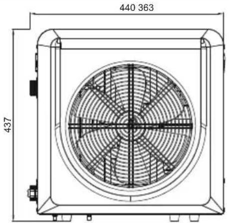
text_image
440 363 437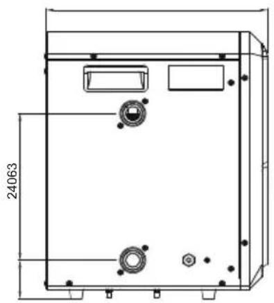
natural_image
Technical line drawing of a rectangular enclosure with internal components and mounting holes, dimensioned 24063 (no text or symbols)MAINTENANCE
CAUTION: You must ensure the Pool Heater is unplugged before beginning the maintenance to avoid risk of injury or death.
- Please check the filtration system regularly. Sand and Filter cartridge must be kept clean and the air must be eliminated to avoid low water flow, which could damage the Pool Heater and reduce the performance.
- If the Pool Heater is not in operation for a long time (especially during the winter season), all the water inside must be discharged.
DISASSEMBLY
DRAINING
To drain the Pool Heater, consult the instructions inside the manual. Drawings in the assembly leaflet are for illustration purposes only. May not reflect actual product. Not to scale.
STORAGE
Remove all accessories; be sure to clean and dry all before storing. If all the parts are not completely dry, mold may result. We strongly recommend removing the Pool Heater when the environment temperature is below 10^ C/50°F. Store the Pool Heater in a dry place with a moderate temperature between 10^ C/50°F and 38^ C/100°F. Keep away from heat sources and fire sources and storage of flammable and explosive materials.
WARRANTY TERMS
For information concerning warranty terms, visit our website at: www.bestwaycorp.com
ERROR CODES
| Malfunction Reason SolutionCode | |||
| Water temperature sensor failure | P1 | Water temperature sensor doesn't work properly. | For assistance, please visit the support section of our website www.bestwaycorp.com |
| Piping temperature sensor failure | P3 | Piping temperature doesn't work properly. | For assistance, please visit the support section of our website www.bestwaycorp.com |
| Ambient temperature sensor failure | P5 | Ambient temperature sensor doesn't work properly. | For assistance, please visit the support section of our website www.bestwaycorp.com |
| Too low or too high ambient temperature protection | E0 | 1. Ambient temperature is out of operating range: below 12°C over 43°C.2. Ambient temperature protection doesn't work properly. | 1. Wait the ambient temperature recover the operation range.2. For assistance, please visit the support section of our website www.bestwaycorp.com. |
| Water flow sensor does not detect water flow. | E3 | 1. Insufficient or no water flow.2. Water flow sensor doesn't work properly. | 1. Check that the filtration system is working.2. For assistance, please visit the support section of our website www.bestwaycorp.com |
CLEANING
Improper cleaning can result in damage to the device.
Cleaning the heat pump
- Do cut off the power supply before the cleaning process
- Do not use any aggressive cleaning agents
- Do not use any sharp or metal objects such as knives, hard putty knives or the like
- Do not use any cleaning brushes
- Do not use a high-pressure cleaner
- Clean the housing and ventilation grill with a slightly damp cloth carefully
• Dry off the heat pump with a dry cloth
SERVICE
| Malfunctions Reason | SolutionObserving | ||
| Pool Heater is not running | LED display off. | No power supply. | Check if there is a power in the wall socket where the Pool heater is connected. |
| LED display is on, and it shows the water temperature | 1. Water temperature is reaching the setting value.2. The pool heater just started. | 1. Verify water temperature setting.2. The Pool Heater has a built-in, 3-minute start-up delay to protect the circuitry and avoid excessive contact wear. | |
| Pool heating effect | 1. LED displays on and it shows water temperature, no error code displays.2. The air from the blower is not cold. | 1. Poor ventilation at the installation site.2. The heating system fails and the fan blades does not operate. | 1. Check the location of heat pump unit and eliminate all obstacles to make good air ventilation.2. For assistance, please visit the support section of our website www.bestwaycorp.com. |
| Water leakage | Water on the floor when the Pool Heater doesn't work. | Water leakage. | 1. Check the connection with the hoses untight, loosen and place the gasket in position.2. For assistance, please visit the support section of our website www.bestwaycorp.com. |
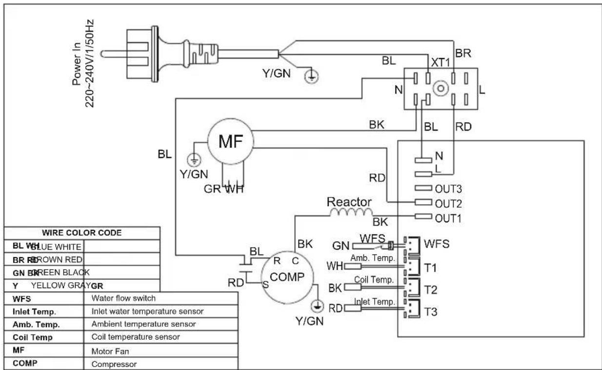
flowchart
graph TD
    A["Power In 220~240V/1/50Hz"] --> B["BL"]
    B --> C["MTF"]
    C --> D["Reactor"]
    D --> E["WFS"]
    E --> F["COMP"]
    F --> G["Inlet Temperature Sensor"]
    F --> H["Coil Temperature Sensor"]
    F --> I["Motor Fan"]
    F --> J["Compressor"]
    style A fill:#f9f,stroke:#333
    style B fill:#ccf,stroke:#333
    style C fill:#cfc,stroke:#333
    style D fill:#fcc,stroke:#333
    style E fill:#cff,stroke:#333
    style F fill:#ffc,stroke:#333
    style G fill:#fcf,stroke:#333
    style H fill:#cff,stroke:#333
    style I fill:#cfc,stroke:#333
    style J fill:#cfc,stroke:#333

natural_image
Technical line drawing of a device casing with mounting holes and a control panel connected to a printer (no text or symbols)natural_image
Technical line drawing of a rectangular enclosure with internal components and mounting holes, dimensioned 24063 (no text or symbols)MANUTENÇÃO
text_image
Technical diagram of a device with labeled components and directional arrows indicating assembly or operation.text_image
28°C 28° Mnatural_image
Technical line drawing of a rectangular enclosure with internal components and dimension lines (no text or symbols)MANUTENCIÓN
natural_image
Technical line drawing of a device rear panel with mounting holes and a control panel connected to a mechanical component (no text or symbols)text_image
28°C 28 Mnatural_image
Technical line drawing of a rectangular enclosure with internal components and mounting holes, dimensioned as 24063 (no text or symbols)WARTUNG
natural_image
Technical line drawing of a device casing with mounting holes and a control panel connected to a printer (no text or symbols)ALTAANLÄMMITTIMEN KÄYTTÖ
natural_image
Technical line drawing of a rectangular enclosure with internal components and mounting holes, dimensioned 24063 (no text or symbols)HUOLTO
text_image
Technical diagram of a device with labeled components and directional arrows indicating assembly or operation.DE ZWEMBADVERWARMER GEBRUIKEN
natural_image
Technical line drawing of a rectangular enclosure with internal components and mounting holes, dimensioned 24063 (no text or symbols)ONDERHOUD:
text_image
Technical diagram of a device with labeled components and directional arrows indicating assembly or operation.UTILIZZO DEL RISCALDATORE DELLA PISCINA
natural_image
Technical line drawing of a rectangular enclosure with internal components and mounting holes, dimensioned 24063 (no text or symbols)MANUTENZIONE
www.bestwaycorp.com.
natural_image
Technical line drawing of a device casing with mounting holes and a control panel connected to a printer (no text or symbols)UTILISATION DU RÉCHAUFFEUR DE PISCINE
natural_image
Technical line drawing of a rectangular enclosure with internal components and mounting holes, dimensioned 24063 (no text or symbols)ENTRETIEN
CONDITIONS DE GARANTIE
text_image
Technical diagram of a device rear panel with labeled components and directional arrows indicating assembly or operation.text_image
28°C 28 Mnatural_image
Technical line drawing of a rectangular enclosure with internal components and mounting holes, dimensioned 24063 (no text or symbols)ΣΥΝΤΗΡΗΣΗ
text_image
Technical diagram of a device rear panel with labeled components and directional arrows indicating assembly or operation.text_image
28°C 28° Mnatural_image
Technical line drawing of a rectangular enclosure with internal components and mounting holes, dimensioned 24063 (no text or symbols)natural_image
Technical line drawing of a device casing with mounting holes and a control panel connected to a printer (no text or symbols)KORZYSTANIE Z OGRZEWANIA BASENU
natural_image
Technical line drawing of a rectangular enclosure with internal components and mounting holes, dimensioned 24063 (no text or symbols)MAINTENANCE
natural_image
Technical line drawing of a device casing with mounting holes and a control panel connected to a printer (no text or symbols)A MEDENCEFÜTÖ HASZNÁLATA
text_image
28°C 28 Mnatural_image
Technical line drawing of a rectangular enclosure with internal components and mounting holes, dimensioned 24063 (no text or symbols)KARBANTARTÁS
natural_image
Technical line drawing of a device casing with mounting holes and a control panel connected to a printer (no text or symbols)ANVÄNDNING AV POOLVÄRMARE
TABELL FÖR UPPVÄRMNING
| Poolens vattenkapacitet Omgivningstemperatur Maximal vattentemperatur | ||
| 30 000 l~20 001 l | 12°C ~15°C | 25°C |
| 15°C ~20°C | 30°C | |
| 20°C ~25°C | 33°C | |
| 20 000 l~10 000 l | 12°C ~15°C | 28°C |
| 15°C ~20°C | 33°C | |
| 20°C ~25°C | 35°C | |
| under 10 000 l | 12°C ~15°C | 30°C |
| 15°C ~20°C | 35°C | |
| 20°C ~25°C | 40°C | |
natural_image
Technical line drawing of a rectangular enclosure with internal components and mounting holes, dimensioned 24063 (no text or symbols)UNDERHÅLL
natural_image
Line drawing of a mechanical device with fan and control panel (no text or symbols)1
6
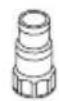
2

3

4

5
| No. | A |
| 1 | ×1 |
| 2 | ×2 |
| 3 | ×3 |
| 4 | ×1 |
| 5 | ×1 |
| 6 | ×1 |

1-a
flowchart
graph TD
    A["Component 1"] --> B["Component 2"]
    B --> C["Component 3"]
    C --> D["Component 4"]
    D --> E["Component 5"]
    E --> F["Component 6"]
    F --> G["Component 7"]
    G --> H["Component 8"]
    H --> I["Component 9"]
    I --> J["Component 10"]
    style A fill:#f9f,stroke:#333
    style B fill:#ccf,stroke:#333
    style C fill:#cfc,stroke:#333
    style D fill:#fcc,stroke:#333
    style E fill:#cff,stroke:#333
    style F fill:#ffc,stroke:#333
    style G fill:#cfc,stroke:#333
    style H fill:#fcc,stroke:#333
    style I fill:#ffc,stroke:#333
    style J fill:#cfc,stroke:#333
1-b
text_image
Diagram of a gasifier or air purifier system with labeled components and directional arrows indicating flow or movement.2
natural_image
Diagram of a portable air conditioner system with cooling fans and heat exchangers (no text or labels)3
text_image
OFF 28°C4
text_image
4 15 +°C 40 -°C 28°C 28°C 28°C V 3s5
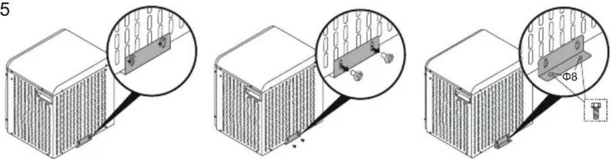
text_image
5 Φ8Bestway®
For support please visit us at:
bestwaycorp.com/support


©2022 Bestway Inflatables & Material Corp.
All rights reserved/Tous droits réservés/Todos los derechos reservados/Alle Rechte vorbehalten/Tutti i diritti riservati
Trademarks used in some countries under license from/
Manufactured, distributed and represented in the European Union by/
Distributed in Australia & New Zealand by Bestway Australia Pty Ltd, Unit 2/98-104 Carnarvon St Silverwater, NSW 2128, Australia
Tel: Australia: (+61) 2 9037 1388; New Zealand: 0800 142 101
Distributed in United Kingdom by Bestway Corp UK Ltd. 8 Wentworth Road, Heathfield Industrial Estate, Newton Abbot, Devon, TQ12 6TL
Exported by/Exporté par/Exportado por/Exportiert von/Esportato da
Bestway (Hong Kong) International Ltd./Bestway Enterprise Company Limited
Suite 713, 7/Floor, East Wing, Tsim Sha Tsui Centre, 66 Mody Road, Kowloon, Hong Kong
www.bestwaycorp.com