
IAN 401421 - Concrete Mixer PARKSIDE - Free user manual and instructions
Find the device manual for free IAN 401421 PARKSIDE in PDF.

| Product type | Concrete mixer |
| Brand | Parkside |
| Model | IAN 401421 |
| Power supply | 230 V~ / 50 Hz |
| Motor power | 220 W |
| Drum capacity | 62 L |
| Motor speed (no load) | 2850 min⁻¹ |
| Drum speed | 27.5 min⁻¹ |
| Dimensions (L × W × H) | 1161 × 550 × 935 mm |
| Weight | 26 kg |
| Protection class | II (double insulation) |
| Protection rating | IP44 |
| Operating mode | S6 30% (10 min cycle) |
| Guaranteed sound power level | 85 dB(A) |
| Intended use | Concrete and mortar for domestic use |
| Safety features | On/Off switch, thermal protection, safety stop |
| Transport | Transport wheels and folding stand |
| Routine maintenance | Cleaning the drum after use, checking the belt |
| Wear parts | V-belt |
| Warranty | 3 years (according to conditions) |
Frequently Asked Questions - IAN 401421 PARKSIDE
User questions about IAN 401421 PARKSIDE
0 question about this device. Answer the ones you know or ask your own.
Ask a new question about this device
Download the instructions for your Concrete Mixer in PDF format for free! Find your manual IAN 401421 - PARKSIDE and take your electronic device back in hand. On this page are published all the documents necessary for the use of your device. IAN 401421 by PARKSIDE.
USER MANUAL IAN 401421 PARKSIDE
natural_image
Exterior view of a black outdoor concrete mixer with wheels and a control panel (no text or symbols visible)
CEMENT MIXER - PCM 62 A1 BETONMISCHER - PCM 62 A1 BETONNIÈRE - PCM 62 A1
GBE
CEMENT MIXER
Operating and Safety Instructions
Translation of Original Operating Manual
FR BE
BÉTONNIÈRE
Before reading, unfold the page containing the illustrations and familiarise yourself with all functions of the device.
DE AT CH
GB / IE Operating and Safety Instructions Page 01
3
natural_image
Technical line drawing of two mechanical fan assemblies with a circular component above (no text or symbols)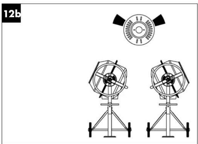
natural_image
Technical diagram showing two identical mechanical fan assemblies with a circular component above, labeled '12b' in the top-left corner (no text or symbols on the diagrams themselves)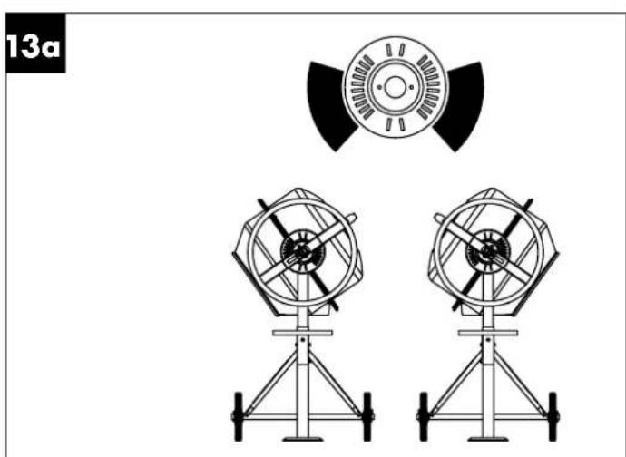
natural_image
Technical line drawing of two radar or fan components mounted on a tripod stand, with a circular component above (no text or symbols)13b
natural_image
Technical line drawing of a mechanical device with top and side views (no text or symbols)14
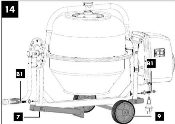
Table of contents: Page:
- Explanation of the symbols on the device....2
- Introduction......4
- Device description (Fig. 1 + 2) ....4
- Scope of delivery (Fig. 3)....4
- Proper use....4
- Safety information....5
- Technical data....6
- Unpacking 6
- Assembly / Before commissioning....6
- Start up 7
- Electrical connection....8
- Cleaning 8
- Transport....9
- Storage 9
- Maintenance....9
- Disposal and recycling 9
- Troubleshooting....10
- Warranty certificate....11
- Exploded view....135
- Declaration of conformity....136
1. Explanation of the symbols on the device

GB IE
Read the operating manual before commissioning!

GB IE
Wear safety shoes.

GB IE
Wear safety gloves!

GB IE
Wear eye protection!

GB IE
Wear dust protection mask!

GB IE
Wear hearing protection!

GB IE
Place the concrete mixer horizontally on level and firm floor!

GB IE
Concrete mixer must not be moved during operation!

GB IE
Concrete mixer may only be operated with the guard fully closed!

GB IE
Do not reach into the drum when it is moving!

GB IE
Caution! Danger of crushing on the sprocket in the grating disc.

GB IE
Do not start the motor until the drum has been fully loaded.

GB IE
Protect the environment! Take the leftover material to an authorized collection point. Make sure that it will not enter the sewage system, the ground or the water.

GB IE
Keep unauthorised persons and children away from the device!

GB IE
The device has protective insulation! Attention! The protection class is only maintained if original insulating materials are used during servicing and the insulation distances are not changed.
GB IE
Pull out the mains plug before cleaning or maintenance!

GB IE
Assembly support! Refer to: Assembly, Fitting the drum upper section.

GB IE
Sound power level specified in dB

GB IE
Protection class II
Attention!
GB IE
We have marked points in this operating manual that impact your safety with this symbol.
2. Introduction
MANUFACTURER:
Scheppach GmbH
Günzburger Straße 69
D-89335 Ichenhausen
DEAR CUSTOMER,
We hope your new tool brings you much enjoyment and success.
NOTE:
In accordance with the applicable product liability laws, the manufacturer of this device assumes no liability for damage to the device or caused by the device arising from:
- Improper handling,
- Failure to comply with the operating instructions.
- Repairs carried out by third parties, unauthorised specialists.
- Installing and replacing non-original spare parts,
• Application other than specified, - Failure of the electrical system in the event of the electrical regulations and VDE provisions 0100, DIN 13 / VDE0113 not being observed.
Please consider:
Read through the complete text in the operating manual before installing and commissioning the device.
The operating manual is intended to help the user to become familiar with the machine and take advantage of its application possibilities in accordance with the recommendations.
The operating manual includes important instructions for safe, proper and economic operation of the device, for avoiding danger, for minimising repair costs and downtimes, and for increasing the reliability and extending the service life of the device.
In addition to the safety instructions in this operating manual, you must also observe the regulations applicable to the operation of the device in your country.
Keep the operating manual package with the machine at all times and store it in a plastic cover to protect it from dirt and moisture. They must be read and carefully observed by all operating personnel before starting the work.
The device may only be used by personnel who have been trained to use it and who have been instructed with respect to the associated hazards. The required minimum age must be observed.
In addition to the safety instructions in this operating manual and the separate regulations of your country, the generally recognised technical rules relating to the operation of such machines must also be observed.
We accept no liability for accidents or damage that occur due to a failure to observe this manual and the safety instructions.
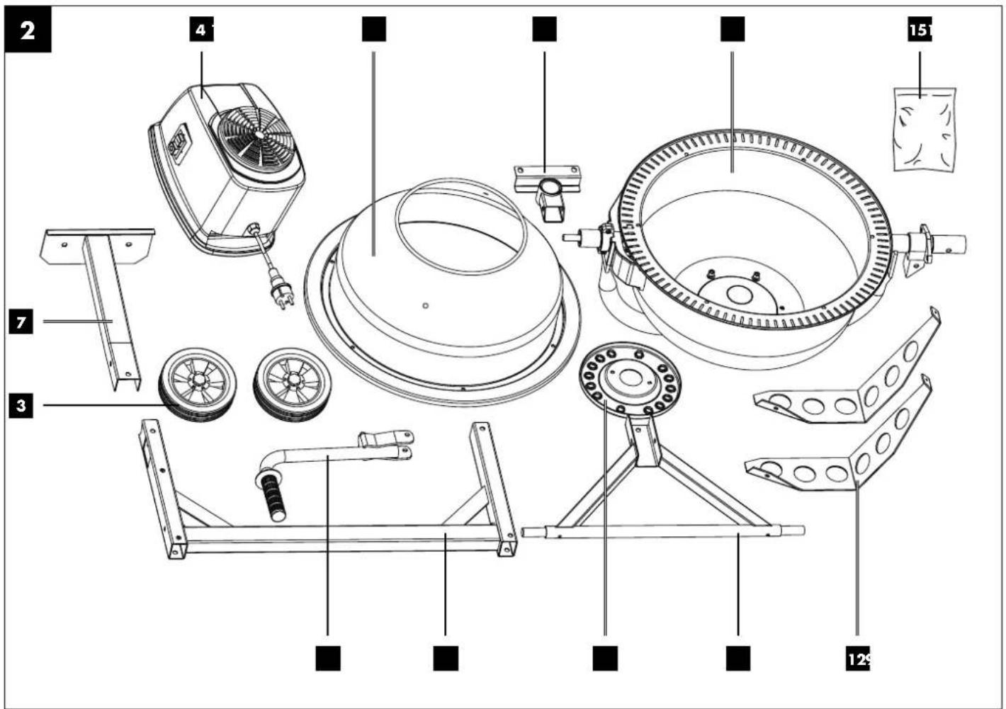
3. Device description (Fig. 1 + 2)
- Pivoting handle
- Machine stand
- Transport wheels
- Motor unit
- On/off switch
- Drum
- Supporting foot
- Frame middle section
- Foot with wheel axle
- Drum lower section
- Bearing support
- Mixing plant
- Drum upper section
- Grating disc
- Enclosed accessories bag (Fig. 3)
- belt
4. Scope of delivery (Fig. 3)
- Motor (4)
- Drum upper section (13)
- Bearing support (11)
- Drum lower section (10)
• Enclosed accessories bag (15) (see Fig. 3) - Mixing plant (12)
- Foot with wheel axle (9)
- Grating disc (14)
• Frame middle section (8) - Pivoting handle (1)
- Foot (7)
- Transport wheels (3)
- Operating manual
5. Proper use
The concrete mixer can be used for home work to mix concrete and mortar. The concrete mixer is only intended for private use in the home and garden.
The machine may only be used in the intended manner. Any use beyond this is improper. The user/operator, not the manufacturer, is responsible for damages or injuries of any type resulting from this.
An element of the intended use is also the observance of the safety instructions, as well as the assembly instructions and operating information in the operating manual.
Relevant accident prevention regulations and other generally recognized safety and technical rules must also be observed.
The machine may only be used, maintained or repaired by persons who are familiar with it and have been informed of the dangers. Any liability of the manufacturer for damages resulting from arbitrary changes to the machine is excluded.
The machine may only be operated with original parts and original accessories from the manufacturer. The safety, operating and maintenance specifications of the manufacturer, as well as the dimensions specified in the technical data, must be observed.
Please observe that our equipment was not designed with the intention of use for commercial or industrial purposes. We assume no guarantee if the equipment is used in commercial or industrial applications, or for equivalent work.
6. Safety information
General safety information
WARNING: When using power tools, the basic safety precautions below must be followed in order to reduce the risk of fire, electric shock, and personal injury.
Please read all instructions before working with this device.
- Observe all safety information and danger notices on the machine.
- Ensure that all of the safety and danger notices on the machine are complete and in legible condition.
- The safety equipment on the machine must not be disassembled or made unusable.
- Check the mains connection cables. Do not use defective connection cables.
- Check for correct function of the device before commissioning.
- The operating personnel must be at least 18 years of age. Trainees must be at least 16 years of age and may only work on the machine under supervision. Keep children away from the concrete mixer.
- Persons under the influence of alcohol, drugs or medication are not permitted to use the equipment.
- The operator is obligated to wear their personal protective equipment (PPE).
- Caution when working: Danger of injury due to rotating parts.
- Only carry out cleaning and maintenance work and rectify faults when the motor is switched off. Remove the mains plug!
- Installation, repairs and maintenance work on the electrical equipment may only be carried out by electricians.
- All protective and safety equipment must be reassembled immediately after repair, maintenance is completed.
- Switch off the motor and pull out the mains plug before leaving the work area!
- Ensure adequate lighting. Poor lighting can significantly increase the danger of injury!
- In case of danger, switch the machine off and pull out the mains plug!
- Never place your hands on moving parts of the machine when it is switched on. There is a danger of entanglement due to the rotating drum and rotating mixing tool.
- The machine must not be operated while being moved to another location!
- The machine may only be positioned on a level surface!
- There is a danger of breathing in toxic vapours and dusts.
Additional safety instructions
- The concrete mixer may only be put into operation fully assembled.
- Check the connection cables for damage before commissioning.
- Wear safety shoes, gloves, safety goggles and a breathing mask.
- Keep hands and feet away from the moving parts.
- Do not reach into the mixing drum while it is running.
- Do not put any objects into the mixing drum while it is running, e.g. shovel or similar.
- Danger of injury when the mixing drum is rotating.
- The concrete mixer may only be operated with original spare parts.
- Repairs to the concrete mixer may only be carried out by authorised specialist companies.
- Do not leave ready-to-use concrete mixer unattended.
- Switch off the machine and pull out the mains plug when leaving the workstation.
Residual risks
The machine has been built according to the state-of-the-art and the recognised technical safety requirements. However, individual residual risks can arise during operation.
• Danger of injury due to rotating parts.
- Health hazard due to electrical power, with the use of improper electrical connection cables.
- Before performing setting or maintenance work, switch the motor off and unplug the mains plug.
• Furthermore, despite all precautions having been met, some non-obvious residual risks may still remain.
- Residual risks can be minimised if the "Safety information" and the "Proper use" together with the operating manual as a whole are observed.
- Avoid accidental start-ups of the machine: Make sure that the ON/OFF switch is set to "0" before inserting the plug into the socket.
- Use the tool that is recommended in this operating manual. This is how to ensure that your machine provides optimum performance.
- Keep your hands away from the work area, when the machine is in operation.
Warning! This power tool generates an electromagnetic field during operation. This field can impair active or passive medical implants under certain conditions.
In order to prevent the risk of serious or deadly injuries, we recommend that persons with medical implants consult with their physician and the manufacturer of the medical implant prior to operating the power tool.
7. Technical data
Motor 230 V\~ / 50 Hz
Motor power 220 Watts
Max. speed 2850 min -1
Max. speed, drum....27.5 rpm
Capacity 621
Protection category IP44
Operating mode* S6 30%
Protection class....II
Dimensions....1161 x 550 x 935 mm
Weight 26 kg
Technical changes reserved!
*S6 30 %: Continuous duty with intermittent loading (operating time 10 min.)
In order to avoid impermissible overheating of the motor, the motor should be driven for only 30% of the operating time with the stipulated nominal power and must then continue to run with no load for the remaining 70% of the operating time.
Noise and vibration
⚠ Warning:
Noise can have serious effects on your health. If the machine noise exceeds 85 dB (A), please wear suitable hearing protection.
Noise data
The noise values have been determined in accordance with EN 62841.
Sound pressure level LΔA 61.14 dB(A)
Uncertainty KpA 2.54 dB
Sound power level LWA 82.12 dB(A)
Uncertainty KWA 2.54 dB
Guaranteed sound power level LWA 85 dB(A)
8. Unpacking
- Open the packaging and carefully remove the device.
- Remove the packaging material, as well as the packaging and transport safety devices (if present).
- Check whether the scope of delivery is complete.
- Check the device and accessory parts for transport damage.
- If possible, keep the packaging until the expiry of the warranty period.
DANGER
The device and the packaging are not children's toys! Do not let children play with plastic bags, films or small parts! There is a danger of choking or suffocating!
9. Assembly / Before commissioning
⚠ Attention!
Always make sure the device is fully assembled before commissioning!
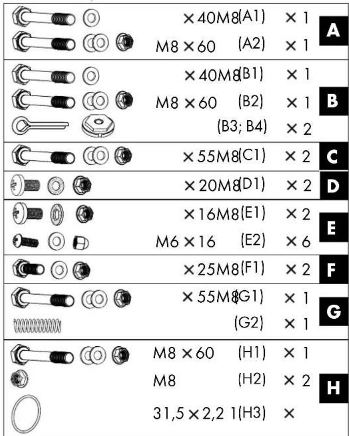
In order to make assembly easier, assembly must be carried out by two persons. The enclosed accessories bag (15) includes all the small parts (A to H) required for assembly (see fig. 3).
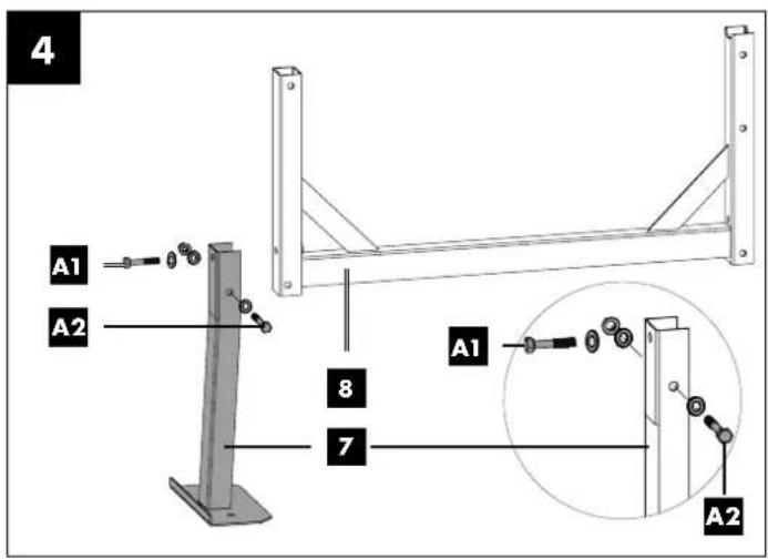
9.1 Installing the foot (7) on the frame middle section (8) (enclosed accessories bag A) (fig. 4)
- Hold the foot (7) to the frame middle section (8). Then attach the M8x60 hexagonal bolt with two washers and an M8 nut (A2). Make sure that the position of the holes and the foot (7) on the frame middle section (8) is correct.
- Then screw in the M8x40 hexagonal bolt with a washer (A1) into the front of the foot (7).
- Tighten all screws using one or two open-ended spanners (size 13) (not included in the scope of delivery).
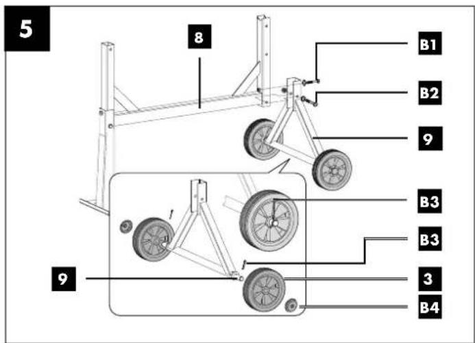
9.2 Installing the foot with wheel axle (9) and transport wheels (3) on the frame middle section (8) (enclosed accessories bag B) (fig. 5)
- First, install the transport wheels (3) by sliding them onto the wheel axles (9). Then insert the split pins (B3) into the hole and bend them apart in order to secure the transport wheels (3).
- Now push the wheel caps (B4) onto the transport wheels (3).
- Then hold the foot with wheel axle (9) to the frame middle section (8). And attach the M8x60 hexagonal bolt with two washers and an M8 nut (B2). Pay attention to the position of the holes.
- Now screw in the M8x40 hexagonal bolt with a washer (B1) into the front of the foot with wheel axle (9).
- Then tighten all screws using one or two open-ended spanners (size 13) (not included in the scope of delivery).
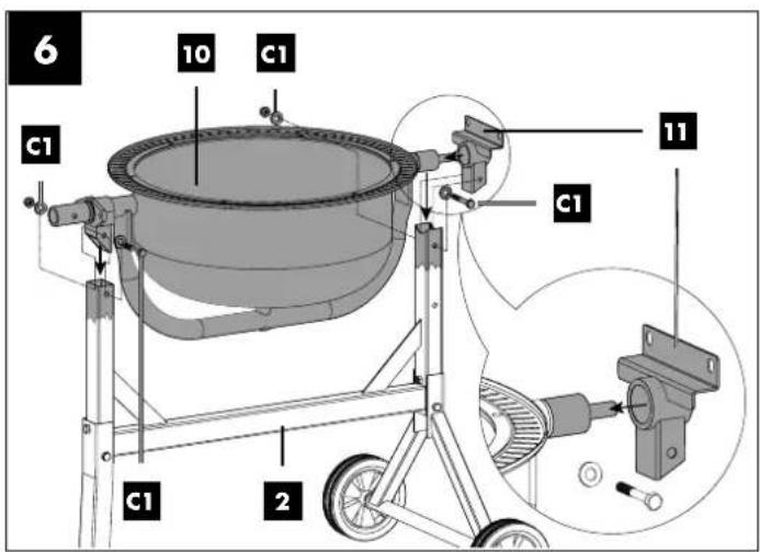
9.3 Installing the drum lower section (10) (enclosed accessories bag C) (fig. 6)
- Fit the bearing support (11) onto the drum lower section (10) at the intended location.
- At the same time, insert the bearing of the drum lower section (10) with the premounted bearing support (11) into the opening of the machine stand (2). Make sure that the bearing support (11) is above the foot with wheel axle (9).
- Pay attention to the position of the holes. Attach the M8x55 screws with two washers and M8 nuts (C1) each onto both sides of the machine stand (2).
- Then tighten all screws using one or two open-ended spanners (size 13) (not included in the scope of delivery).
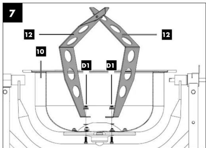
9.4 Installing the mixing plant (12) (enclosed accessories bag D) (fig. 7)
-
Fit the mixing plant (12) onto the drum lower section (10) by attaching an M8x20 fillister head screw, a rubber washer and an M8 nut (D1). Make sure that the holes/surfaces at the top end of the mixing plant (12) are facing outwards. The rubber washer (D1) must be between the mixing plant (12) and the drum lower section (10).
-
The mixing plant (12) is only tightened once the drum upper section (13) has been installed (see section 9.5).
Note: In order to make correct installation of the mixing plant easier, two arrows are attached to the upper and lower drum. If you are not sure whether the mixing plant has been installed correctly, you can test this. To do this, place the upper drum on the lower drum and turn them until the two arrows point towards each other.
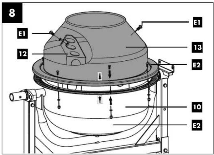
9.5 Installing the drum upper section (13) (enclosed accessories bag E) (fig. 8)
- Put the drum upper section (13) onto the lower drum (10). Make sure that the fixing holes of the upper and lower drum align with each other.
Attention! The glued-on arrows mark the exact alignment of the drum lower section (10) and drum upper section (13).
-
Fix the drum upper section (13) by attaching the M6x16 screws, washers and M6 nuts (E2).
-
Then tighten the screws (E2) crosswise using a Phillips screwdriver and an open-ended spanner size 10 (not included in the scope of delivery).
-
Fasten the top end of the mixing plant (12) by attaching an M8x20 fillister head screw, a rubber washer and an M8 nut (E1). The rubber washer (E1) must be between the mixing plant (12) and the drum upper section (13).
-
Then tighten the screws (D1) and (E1) using a Phillips screwdriver and an open-ended spanner size 13 (not included in the scope of delivery).
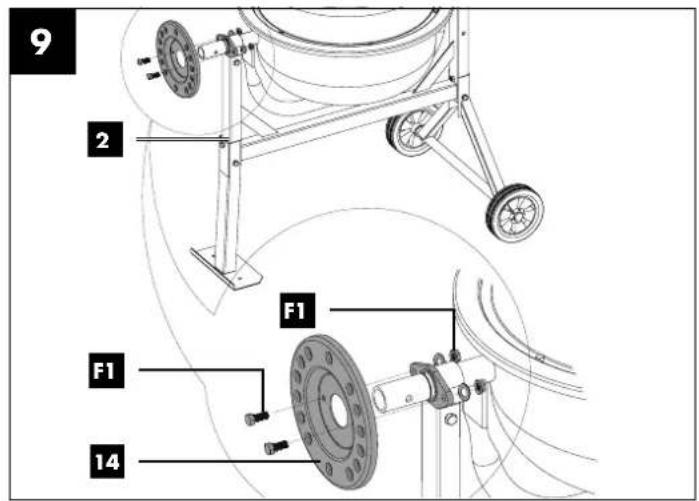
9.6 Installing the grating disc (14) (enclosed accessories bag F) (fig. 9)
-
Install the grating disc (14) by attaching the M8x25 hexagonal bolts, washers and hexagonal nuts (F1) to the machine stand (2).
-
Then tighten all screws using one or two open-ended spanners (size 13) (not included in the scope of delivery).
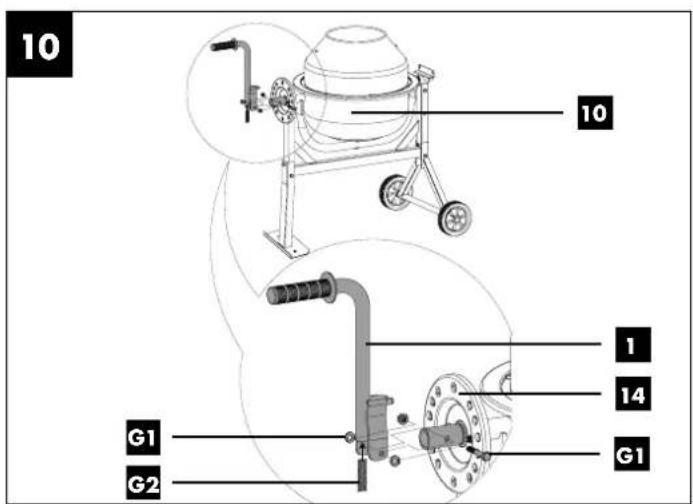
9.7 Installing the pivoting handle (1) (enclosed accessories bag G) (fig. 10)
-
Guide the spring (G2) into the rod tube of the pivoting handle (1) from below.
-
Hold the spring (G2) in place with a finger.
-
Place the pivoting handle (1) above the shaft of the drum lower section (10) so that the spring lies on the shaft.
-
Push the pivoting handle (1) down until the holes in the shaft of the drum lower section (10) align with the holes in the pivoting handle (1).
-
Fasten the pivoting handle (1) using the M8x55 hexagonal bolt, a washer and a nut (G1).
-
Then tighten the screw (G1) using two open-ended spanners size 13 (not included in the scope of delivery) until the pivoting handle (1) can still be turned easily.
Note: The pivoting handle must rest on the shaft so it can rotate and it does not slip off. It must be able to grip easily into the holes of the grating disc (14).
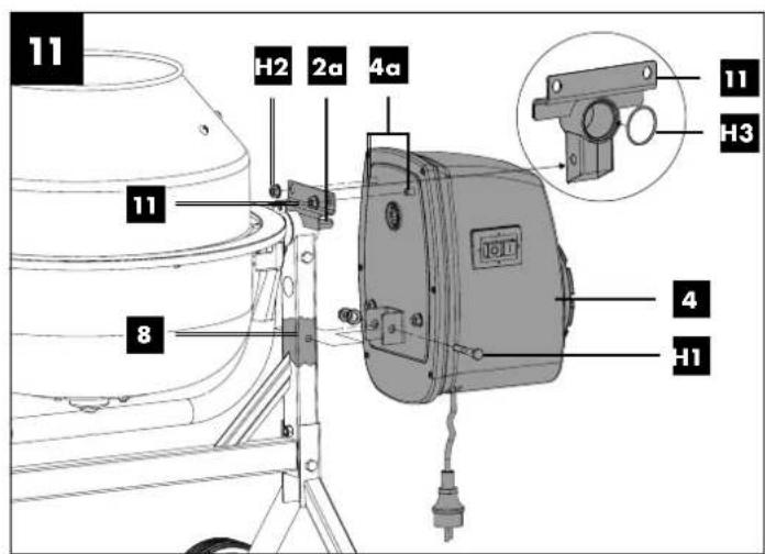
9.8 Installing the motor unit (4) (enclosed accessories bag H) (fig. 11)
- Place the O-ring (H3) into the circular nut in the central hole of the bearing holder (11) on the frame middle section (8).
- Push the motor unit (4) onto the shaft (2a) of the frame middle section (8). Pay attention to the position of the shaft (2a) and threaded bolts (4a) on the frame middle section (8) or the motor unit (4).
- Then fasten the motor unit (4) by attaching a M8x60 hexagonal bolt, a washer and an M8 nut (H1).
- In addition, turn the two M8 nuts (H2) on the threaded bolts (4a) of the motor unit (4).
- Then tighten all screws using one or two open-ended spanners (size 13) (not included in the scope of delivery).
10. Start up
Attention!
Always make sure the device is fully assembled before commissioning!
Only operate the concrete mixer if no parts are missing or faulty and if the connection cable is not damaged.
10.1 Setup
- Set up the concrete mixer horizontally on a level, non-tilting and firm surface. Prevent the machine from sinking into the ground.
- Do not set up the concrete mixer on the connection cable!
- Lay the connection cable so that it cannot be kinked, crushed or damaged in any other way.
Note:
The drum (6) must be able to swivel to the right and left. Make sure that a sufficient container (e.g. a mortar bucket) is beneath the drum (6) for emptying the drum (6). When setting up the machine, make sure that the mixing drum can be emptied freely.
10.2 Switching on/off (fig. 1) ⚠️ ATTENTION!
Risk of injury!
A rotating mixing drum can lead to injuries.
- Do not reach into the mixing drum while it is running.
- Do not put any objects into the mixing drum while it is running (e.g. shovel or similar).
- Plug the device into the socket.
- Press the ON/OFF switch (5) "1" (green button) to start the device.
- Press the ON/OFF switch (5) "0" (red button) to switch off the device.
10.2.1. Thermal protection
With overloading or overheating, the protective shut-down integrated in the device switches off for safety reasons.
- Wait approx. 15 minutes until the motor has cooled down.
- Restart the device by pressing the ON/OFF switch (5) "I" (green button).
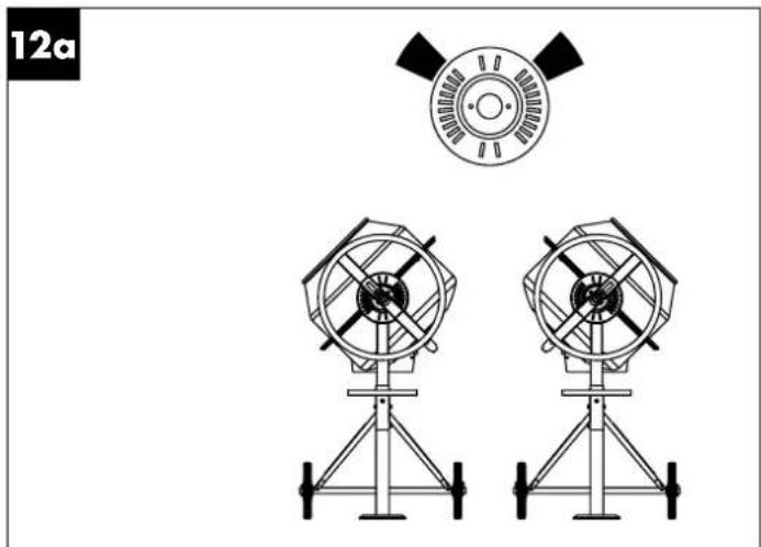
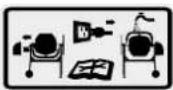
10.3 Adjusting the drum (fig. 1, fig. 12a/12b)
The concrete mixer must be engaged in a certain mixing position for concrete and mortar production. Only the correct mixing position ensures the best mixing ratio and guarantees a trouble-free working process.
- Always hold the pivoting handle (1) firmly to adjust the drum (6).
- Release the swivelling device by pulling the pivoting handle (1) towards you. The latch is released from the grating disc (14).
-
Swivel the mixing drum (6) to the recess corresponding to your mix. The mixing positions are marked on the grating disc (14) by recesses:
• Fig. 12a: Drum position for the production of mortar
• Fig. 12b: Drum position for the production of concrete -
When the drum (6) is in the desired position, engage the pivoting handle (1) into the grating disc (14) again.
10.4 Filling (fig. 12a + 12b)
ATTENTION!
Health risk and danger of injury!
Breathing in dust can cause damage to health. Do not touch the cement or admixtures without protective gloves.
- Wear a breathing mask.
- Wear protective gloves and never reach into the mixing drum while it is running.
⚠ WARNING!
Tipping hazard!
Pay attention to the stability of the concrete mixer before filling.
- Only operate the concrete mixer on a firm, level (non-tilting) surface.
-
Do not change the location of the concrete mixer when filling or when the drum is running.
-
Press the ON/OFF switch (5) "I" (green button) to start the device.
- Check the mixing position on the grating disc (14):
• Fig. 12a: Drum position for the production of mortar
• Fig. 12b: Drum position for the production of concrete - Fill the mix while the drum is running (6). Do not overfill the drum (6). Caution! Danger from moving parts!
- Do not throw material into the mixing drum with great momentum in order to prevent it sticking to the underside of the drum. Feed in the material in small portions.
- Before filling, make sure that the opening of the drum (6) is aligned so that no mix can fall out of the drum (6).
Note: Ask a specialist for advice about the composition and quality of the mix.
10.5 Emptying (fig. 13a)
- Unlock the swivelling device by pulling the pivoting handle (1) towards you. The latch is released from the grating disc (14).
- Now swivel the drum (6) downwards slowly to empty it.
- Place a sufficient container (e.g. a mortar bucket) beneath the drum (6). Make sure that no mix can get onto the floor.
11. Electrical connection
The electrical motor installed is connected and ready for operation. The connection complies with the applicable VDE and DIN provisions.
The customer's mains connection as well as the extension cable used must also comply with these regulations.
11.1 Damaged electrical connection cable
The insulation on electrical connection cables is often damaged.
This may have the following causes:
- Pressure points, where connection cables are passed through windows or doors.
- Kinks where the connection cable has been improperly fastened or routed.
- Places where the connection cables have been cut due to being driven over.
• Insulation damage due to being ripped out of the wall outlet. - Cracks due to the insulation ageing.
Such damaged electrical connection cables must not be used and are life-threatening due to the insulation damage.
Check the electrical connection cables for damage regularly. Ensure that the connection cables are disconnected from electrical power when checking for damage.
Electrical connection cables must comply with the applicable VDE and DIN provisions. Only use connection cables marked with H07RN.
The printing of the type designation on the connection cable is mandatory.
For single-phase AC motors, we recommend a fuse rating of C 16A or K 16A for machines with a high starting current (from 3000 watts)!
12. Cleaning
⚠ WARNING!
Risk of injury!
The product can start unexpectedly and cause injuries.
- Switch off the motor before carrying out any cleaning or maintenance work.
- Disconnect the mains plug before carrying out any cleaning work.
NOTE!
Risk of damage!
Damage to the motor can occur if water penetrates into the motor unit. Do not tap on the mixing drum with hard objects (hammer, shovel, etc.). A dented mixing drum impairs the mixing process and can be more difficult to clean.
- Clean the product with a brush or a scraper.
- Do not immerse the product in water or other liquids and do not spray the motor unit with a high-pressure cleaner.
We recommend that you thoroughly clean the inside and outside of the device directly after every use. Never remove dirt with a hammer, shovel or the like.
After each use of the concrete mixer:
- Clean the drum (6) with water and remove cement and mortar crusts with a brush or a scraper.
- To clean the inside of the drum, circulate a few shovels of gravel with water.
13. Transport
⚠ WARNING!
Risk of injury!
The product can start unexpectedly and cause injuries.
- Switch the motor off before transporting.
- Pull out the mains plug.
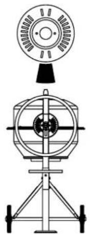
13.1 Vehicle transport (fig. 13b/14)
- Release the swivelling device by pulling the pivoting handle (1) towards you. The latch is released from the grating disc (14).
- Now place the drum (6) with the filling opening facing downwards. (fig. 13b)
- Remove the screws (B1) from the foot (7) and (B1) from the foot with wheel axle (9).
- Fold up the foot (7) and the foot with wheel axle (9).
- Secure the concrete mixer from sliding with a tension strap.
- Do not lift the concrete mixer with a crane.
13.2 Transport at the workplace (fig. 13b)
- Release the swivelling device by pulling the pivoting handle (1) towards you. The latch is released from the grating disc (14).
- Now place the drum (6) with the filling opening facing downwards.
- For a brief transport, tilt the concrete mixer gently and transport it on the transport wheels (3).
14. Storage
Store the device and its accessories in a dark, dry and frost-free place that is inaccessible to children. The optimum storage temperature lies between 5 and 30 °C.
Cover the concrete mixer to protect it from dust and moisture. Store the operating manual with the power tool.
15. Maintenance
⚠ WARNING!
Risk of injury!
The product can start unexpectedly and cause injuries.
- Switch the motor off before performing any maintenance work.
- Disconnect the mains plug before carrying out any maintenance work.
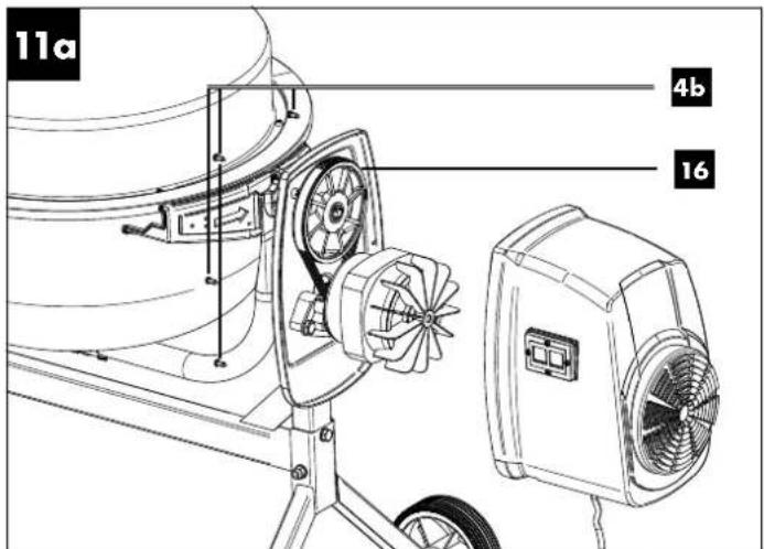
15.1 Checking belt tension (fig. 11a)
The belt tension is adjusted correctly in the factory. The belt tension cannot be readjusted.
- Remove the cover of the motor unit (4) by loosening the screws (4b) on the motor unit (4).
-
Check the belt tension. By pressing on the belt (16) with your finger, the belt should give approx. 5 mm.
-
Put the cover of the motor unit (4) back on and tighten the screws (4b).
15.2 Replacing the belt (fig. 11a)
Belts are wearing parts that have to be replaced after a certain time.
- Remove the cover of the motor unit (4) by loosening the screws (4b) on the motor unit (4).
- Pull off the motor cover.
- The ribbed side of the new V-belt (16) should face outwards when inserted. Make sure the lower part of the V-belt is installed first.
- Check the belt tension. By pressing on the belt (16) with your finger, the belt should give approx. 5 mm. It is not possible to retention the belt.
- Put the cover of the motor unit (4) back on and tighten the screws (4b).
15.3 Connections and repairs
Connections and repair work on the electrical equipment may only be carried out by electricians.
Please provide the following information in the event of any enquiries:
• Type of current for the motor
• Data of machine type plate
15.4 Service information
With this product, it is necessary to note that the following parts are subject to natural or usage-related wear, or that the following parts are required as consumables.
Wearing parts*: Belt
* may not be included in the scope of supply!
16. Disposal and recycling
The device is supplied in packaging to avoid transport damages. This packaging is raw material and can thus be used again or can be reintegrated into the raw material cycle.
The device and its accessories are made of different materials, such as metals and plastics. Take defective components to special waste disposal sites. Check with your specialist dealer or municipal administration!

The packaging is wholly composed of environmentally-friendly materials that can be disposed of at a local recycling centre.
Contact your local refuse disposal authority for more details of how to dispose of your worn-out electrical devices.
Old devices must not be disposed of with household waste!

This symbol indicates that this product must not be disposed of together with domestic waste in compliance with the Directive (2012/19/EU) pertaining to waste electrical and electronic equipment (WEEE). This product must be handed over at the intended collection point. This can be done, for example, by returning it when purchasing a similar product or delivering it to an authorised collection point for the recycling of old electrical and electronic devices. Improper handling of waste equipment may have negative consequences for the envi-
ronment and human health due to potentially hazardous substances that are often contained in electrical and electronic equipment. By properly disposing of this product, you are also contributing to the effective use of natural resources. You can obtain information on collection points for waste equipment from your municipal administration, public waste disposal authority, an authorised body for the disposal of waste electrical and electronic equipment or your waste disposal company.
17. Troubleshooting
| Fault Possible cause Remedy | ||
| Motor does not start | No mains voltage Check the safeguard | |
| Connection cable missing Have checked or replaced by an electrician | ||
| Engine switches off | Engine overloaded Let the engine cool down | |
| Supply and exhaust air openings on the motor unit are contaminated | Clean supply and exhaust air openings | |
| Engine runs, drum stands still V-belt slipping Replace V-belt | ||
18. Warranty certificate
Dear Customer,
All of our products undergo strict quality checks to ensure that they reach you in perfect condition. In the unlikely event that your device develops a fault, please contact our service department at the address shown on this guarantee card. Of course, if you would prefer to call us then we are also happy to offer our assistance under the service number printed below. Please note the following terms under which guarantee claims can be made:
- These guarantee terms cover additional guarantee rights and do not affect your statutory warranty rights. We do not charge you for this guarantee.
- Our guarantee only covers problems caused by material or manufacturing defects, and it is restricted to the rectification of these defects or replacement of the device. Please note that our devices have not been designed for use in commercial, trade or industrial applications. Consequently, the guarantee is invalidated if the equipment is used in commercial, trade or industrial applications or for other equivalent activities. The following are also excluded from our guarantee: compensation for transport damage, damage caused by failure to comply with the installation/assembly instructions or damage caused by unprofessional installation, failure to comply with the operating instructions (e.g. connection to the wrong mains voltage or current type), misuse or inappropriate use (such as overloading of the device or use of non-approved tools or accessories), failure to comply with the maintenance and safety regulations, ingress of foreign bodies into the device (e.g. sand, stones or dust), effects of force or external influences (e.g. damage caused by the device being dropped) and normal wear resulting from proper operation of the device.
The guarantee is rendered null and void if any attempt is made to tamper with the device.
- The guarantee is valid for a period of 3 years starting from the purchase date of the device. Guarantee claims should be submitted before the end of the guarantee period within two weeks of the defect being noticed. No guarantee claims will be accepted after the end of the guarantee period. The original guarantee period remains applicable to the device even if repairs are carried out or parts are replaced. In such cases, the work performed or parts fitted will not result in an extension of the guarantee period, and no new guarantee will become active for the work performed or parts fitted. This also applies when an on-site service is used.
- In order to assert your guarantee claim, please contact the service partner shown below. If the complaint is within the guarantee period, we will provide you with a return slip, with which you can return your defective device free of charge to us. It would help us if you could describe the nature of the problem in as much detail as possible. If the defect is covered by our guarantee then your device will either be repaired immediately and returned to you, or we will send you a new device.
Of course, we are also happy offer a chargeable repair service for any defects which are not covered by the scope of this guarantee or for units which are no longer covered. To take advantage of this service, please send the device to our service address.
Service-Hotline (GB): Service-Hotline (IE):
00800 4003 4003 00800 4003 4003
(0,00 EUR/Min.) (0,00 EUR/Min.)
Service-Email (GB): Service-Email (IE):
service.GB@scheppach.com
service.IE@scheppach.com
Service Address (GB): Service Address (IE):
Forest Park & Garden LetMeRepair
Coed Court, Taffsmead Road 1 Langlands Court / Kelvin South Business Park
Treforest, Ind. Estate, Pontypridd CF375SW East Kilbride G75 0YB

At www.lidl-service.com you can download this and many more manuals, product videos plus installation software.
The QR code takes you directly to the Lidl service page (www.lidl-service.com) and you can open your operating manual by entering the article number (IAN) 401421_2107.
Inhalt:
Seite:
Günzburger Straße 69
D-89335 Ichenhausen
VEREHRTER KUNDE,
Günzburger Straße 69
D-89335 Ichenhausen
CHER CLIENT,
Service-hotline (BE):
00800 4003 4003
(0,00 €/Min.)
Email du service (FR):
service.FR@scheppach.com
E-mailadres (BE):
service.BE@scheppach.com
Scheppach France Strassburg
2, Impasse Jean Millot
FR - 6700 Strasbourg
Serviceadres (BE):
Service Center Bruyninckx
Guldendelle 30
BE - 1930 Zventem (Nossegem)

Günzburger Straße 69
D-89335 Ichenhausen
GEACHTE KLANT,
Service-hotline (BE):
00800 4003 4003
(0,00 €/Min.)
E-mailadres / Email du service (NL):
service.NL@scheppach.com
E-mailadres (BE):
service.BE@scheppach.com
Serviceadres / Adresse du service (NL):
Günzburger Straße 69
D-89335 Ichenhausen
VÁŽENÝ ZÁKAZNÍKU,
Günzburger Straße 69
D-89335 Ichenhausen
SZANOWNY KLIENCIE,
Günzburger Straße 69
D-89335 Ichenhausen
VÁŽENÝ ZÁKAZNÍK,
Günzburger Straße 69
D-89335 Ichenhausen
ESTIMADO CLIENTE:
Günzburger Straße 69
D-89335 Ichenhausen
KÆRE KUNDE
Günzburger Straße 69
D-89335 Ichenhausen
GENTILE CLIENTE,
service.IT@scheppach.com
Günzburger Straße 69
D-89335 Ichenhausen
KEDVES ÜGYFELÜNK!
Günzburger Straße 69
D-89335 Ichenhausen
SPOŠTOVANI KUPEC,
želimo vam veliko veselja in uspeha pri delu z vašo novo napravo.
NAPOTEK:
Günzburger Straße 69
EG Declaration of Conformity
Translation of the original CE declaration of conformity
Standard references:
EN 55014-1:2017; EN 55014-2:2015; EN 61000-3-2:2014; EN 61000-3-3:2013; EN 12151:2007; EN 60204-1:2018
This declaration of conformity is issued under the sole responsibility of the manufacturer.
Subject to change without notice
Documents registrar: Thomas Schuster Günzburger Str. 69, D-89335 Ichenhausen
CE
SCHEPPACH GMBH
Günzburger Str. 69
D-89335 Ichenhausen

FSC
www.fsc.org
MIX
Paper from responsible sources
C127328

FSC
www.fsc.org
MIXTE
- CEMENT MIXER - PCM 62 A1 BETONMISCHER - PCM 62 A1 BETONNIÈRE - PCM 62 A1
- CEMENT MIXER
- BÉTONNIÈRE
- Table of contents: Page:
- Explanation of the symbols on the device
- Introduction
- MANUFACTURER:
- DEAR CUSTOMER,
- NOTE:
- Please consider:
- Device description (Fig. 1 + 2)
- Scope of delivery (Fig. 3)
- Proper use
- Safety information
- General safety information
- Please read all instructions before working with this device.
- Additional safety instructions
- Residual risks
- The machine has been built according to the state-of-the-art and the recognised technical safety requirements. However, individual residual risks can arise during operation.
- Technical data
- Noise and vibration
- ⚠ Warning:
- Noise data
- Unpacking
- DANGER
- Assembly / Before commissioning
- ⚠ Attention!
- Installing the foot (7) on the frame middle section (8) (enclosed accessories bag A) (fig. 4)
- Installing the foot with wheel axle (9) and transport wheels (3) on the frame middle section (8) (enclosed accessories bag B) (fig. 5)
- Installing the drum lower section (10) (enclosed accessories bag C) (fig. 6)
- Installing the mixing plant (12) (enclosed accessories bag D) (fig. 7)
- Installing the drum upper section (13) (enclosed accessories bag E) (fig. 8)
- Installing the grating disc (14) (enclosed accessories bag F) (fig. 9)
- Installing the pivoting handle (1) (enclosed accessories bag G) (fig. 10)
- Installing the motor unit (4) (enclosed accessories bag H) (fig. 11)
- Start up
- Attention!
- Setup
- Switching on/off (fig. 1) ⚠️ ATTENTION!
- Risk of injury!
- Thermal protection
- Adjusting the drum (fig. 1, fig. 12a/12b)
- Filling (fig. 12a + 12b)
- Health risk and danger of injury!
- ⚠ WARNING!
- Tipping hazard!
- Emptying (fig. 13a)
- Electrical connection
- Damaged electrical connection cable
- Cleaning
- NOTE!
- Risk of damage!
- Transport
- Vehicle transport (fig. 13b/14)
- Transport at the workplace (fig. 13b)
- Storage
- Maintenance
- Checking belt tension (fig. 11a)
- Replacing the belt (fig. 11a)
- Connections and repairs
- Please provide the following information in the event of any enquiries:
- Service information
- Disposal and recycling
- Old devices must not be disposed of with household waste!
- Troubleshooting
- Warranty certificate
- Inhalt:
- Seite:
- VEREHRTER KUNDE,
- CHER CLIENT,
- GEACHTE KLANT,
- Service-hotline (BE):
- E-mailadres / Email du service (NL):
- E-mailadres (BE):
- Serviceadres / Adresse du service (NL):
- VÁŽENÝ ZÁKAZNÍKU,
- SZANOWNY KLIENCIE,
- VÁŽENÝ ZÁKAZNÍK,
- ESTIMADO CLIENTE:
- KÆRE KUNDE
- GENTILE CLIENTE,
- KEDVES ÜGYFELÜNK!
- SPOŠTOVANI KUPEC,
- NAPOTEK:
- EG Declaration of Conformity
- Standard references:
- EN 55014-1:2017; EN 55014-2:2015; EN 61000-3-2:2014; EN 61000-3-3:2013; EN 12151:2007; EN 60204-1:2018
Brand : PARKSIDE
Model : IAN 401421
Category : Concrete Mixer