
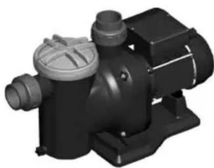
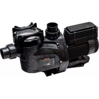
ARAL C 1500 - Pump ASTRALPOOL - Free user manual and instructions
Find the device manual for free ARAL C 1500 ASTRALPOOL in PDF.
| Product Type | Pool Filtration Pump |
| Brand | AstralPool |
| Model | ARAL C 1500 |
| Category | Pump |
| Use | Prefiltering and recycling pool water |
| Maximum water temperature | 35 °C |
| Water type | Clean water |
| Motor type | Single-phase with integrated thermal protector |
| Power supply | 230 V / 50 Hz |
| Electrical protection | Residual current device (RCD) ≤ 30 mA |
| Disconnection device | Multi-pole disconnector with 3 mm opening |
| Prefilter | Yes, with removable basket |
| Suction connection | By screw fittings with sealing gaskets |
| Discharge connection | By screw fittings with sealing gaskets |
| Suction piping slope | 2% towards the pump |
| Maximum suction height above water level | 2 m (0.02 MPa) |
| Maintenance | Regular cleaning of the prefilter basket |
| Winter drainage | Yes, via drain plug |
| Consumable components | Seals (1 year), mechanical seal (1 year), bearings (1 year) |
| Service interval | Every 100 hours of operation or as needed |
| Mounting | Floor mounting with anchoring (foot with screws) |
| Safety | Do not use if people are in the water; cut off power before intervention |
| Standards | Compliant with standard HD 384.7.702 for pools |
Frequently Asked Questions - ARAL C 1500 ASTRALPOOL
User questions about ARAL C 1500 ASTRALPOOL
0 question about this device. Answer the ones you know or ask your own.
Ask a new question about this device
Download the instructions for your Pump in PDF format for free! Find your manual ARAL C 1500 - ASTRALPOOL and take your electronic device back in hand. On this page are published all the documents necessary for the use of your device. ARAL C 1500 by ASTRALPOOL.
USER MANUAL ARAL C 1500 ASTRALPOOL
INSTALLATION AND GENERAL MAINTENANCE MANUAL MANUEL D'INSTALLATION ET MAINTENANCE GÉNÉRAL MANUAL DE INSTALACIÓN Y MANTENIMIENTO GENERAL MANUALE DI INSTALLAZIONE E MANUTENZIONE GENERALE ALLGEMEINES INSTALLATIONS- UND MONTAGEARBEITEN MANUAL DE INSTALAÇÃO E MANUTENÇÃO GERAL
ORIGINAL INSTRUCTIONS INSTRUCTIONS D'ORIGINE INSTRUCCIONES ORIGINALES ISTRUZIONI ORIGINALI ORIGINALANLEITUNG INSTRUÇÕES ORIGINAIS
natural_image
3D rendering of a black industrial pump or motor component with cylindrical and flanged sections (no visible text or symbols)LEADER FLOW B.M.
natural_image
3D rendering of a mechanical pump or motor assembly (no visible text or symbols)COLUMBIA
natural_image
3D rendering of a black industrial pump or motor component with no visible text or symbols
natural_image
3D rendering of a black industrial pump or motor component (no visible text or symbols)SENAGLASS PLUS
natural_image
3D rendered mechanical component with black body and gray valve (no text or symbols visible)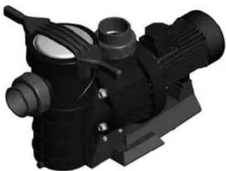
natural_image
3D rendered mechanical component with black and white sections, no visible text or symbolsMAXIM

natural_image
Mechanical assembly of a motor and pump unit (no visible text or symbols)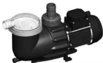
natural_image
3D rendering of a black industrial pump or motor with inlet and outlet pipes (no visible text or symbols)ASTRAMAX COMPACT
POOL PUMPS
POMPES POUR PISCINES
This manual contains basic information on the safety measures to be adopted during installation and start-up. The fitter and the user must therefore read the instructions before installation and start-up.
1.GENERAL SAFETY INSTRUCTIONS
These symbols ( ⚠️ ⚠️ ⚠️ ) indicate the possibility of danger where the corresponding instructions are not followed.

DANGER. Risk of electrocution.
Failure to abide by these instructions may lead to the risk of electrocution.
DANGER.

Failure to abide by these instructions may lead to the risk of injury or damage.
WARNING.

Failure to abide by these instructions may lead to the risk of damage to the pump or the installation.
2.GENERAL SAFETY REGULATIONS
GENERAL

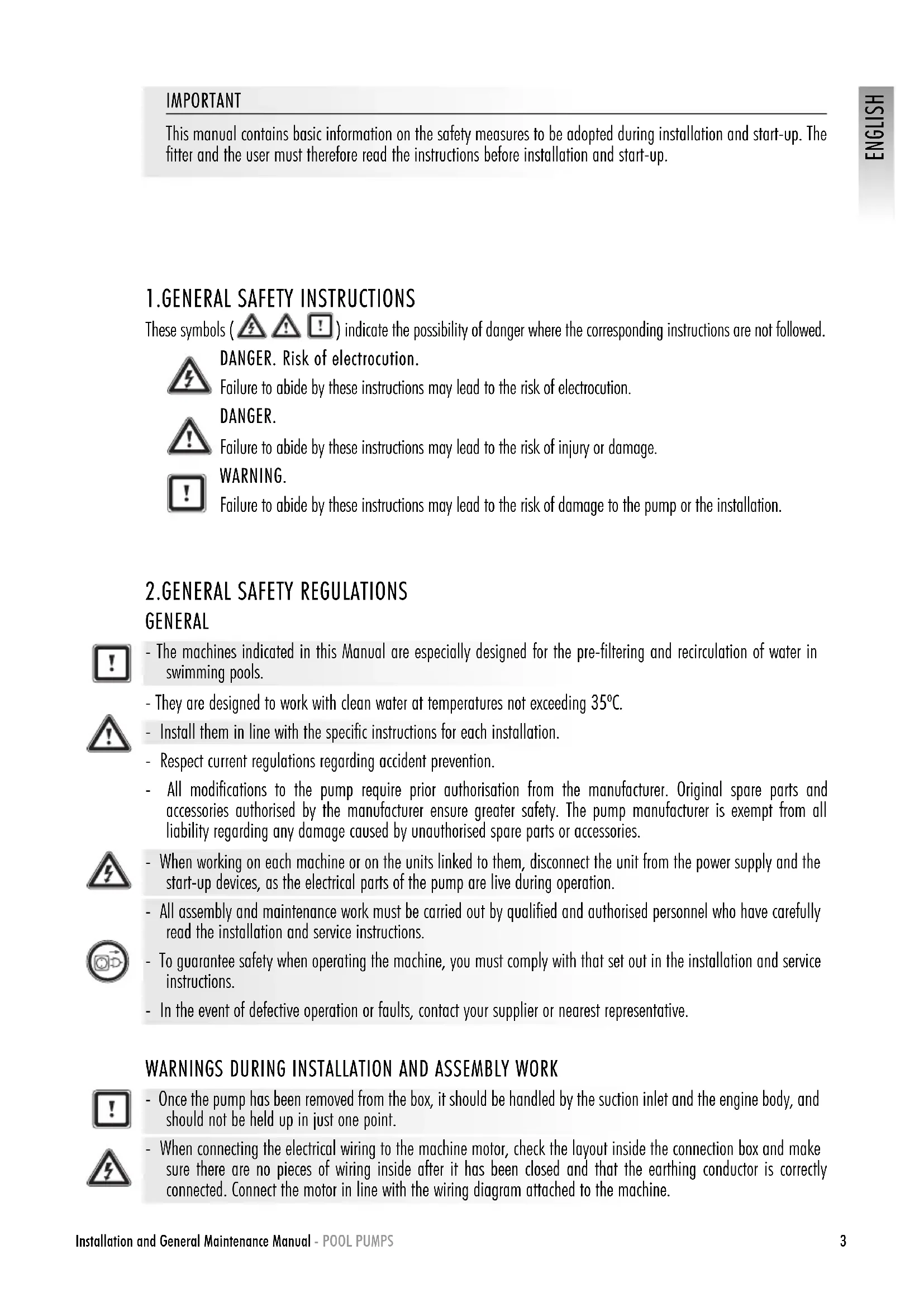
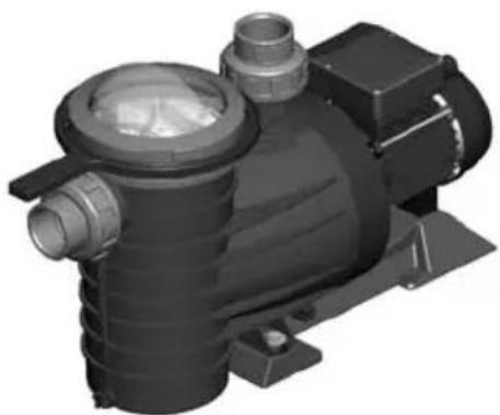
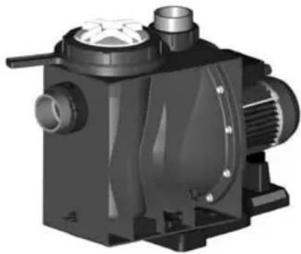
- The machines indicated in this Manual are especially designed for the pre-filtering and recirculation of water in swimming pools.

- They are designed to work with clean water at temperatures not exceeding 35^ C.
- Install them in line with the specific instructions for each installation.
- Respect current regulations regarding accident prevention.
- All modifications to the pump require prior authorisation from the manufacturer. Original spare parts and accessories authorised by the manufacturer ensure greater safety. The pump manufacturer is exempt from all liability regarding any damage caused by unauthorised spare parts or accessories.

- When working on each machine or on the units linked to them, disconnect the unit from the power supply and the start-up devices, as the electrical parts of the pump are live during operation.
- All assembly and maintenance work must be carried out by qualified and authorised personnel who have carefully read the installation and service instructions.

- To guarantee safety when operating the machine, you must comply with that set out in the installation and service instructions.
- In the event of defective operation or faults, contact your supplier or nearest representative.
WARNINGS DURING INSTALLATION AND ASSEMBLY WORK

- Once the pump has been removed from the box, it should be handled by the suction inlet and the engine body, and should not be held up in just one point.

- When connecting the electrical wiring to the machine motor, check the layout inside the connection box and make sure there are no pieces of wiring inside after it has been closed and that the earthing conductor is correctly connected. Connect the motor in line with the wiring diagram attached to the machine.

- Make sure that the electrical wiring connections to the machine terminal box are well mounted and screwed tight to the connection terminals.
- The equipment should be connected to an alternating current supply (see data on the pump's plate) with earth connection, protected by a residual current device (RCD) having a rated residual operating current not exceeding 30 mA.
- Correctly use the seal of the terminal box for the electrical motor to prevent water getting in. Likewise, position and tighten the gland inside the cable duct of the terminal box.
- Make sure that water is unable to enter the motor or the live electrical parts.
- Where the intended use is not as indicated, additional technical adaptations and regulations may be required.
WARNINGS DURING START-UP

Before starting the machine, check the calibration of the electric protection devices on the motor and that the protection against electrical and mechanical contacts is correctly positioned and secure.
NOTE
The pool should not be used while the pumping equipment is running.
Do not use the pump if anyone is in contact with the water.
WARNINGS DURING ASSEMBLY AND MAINTENANCE WORK

- Take into account national installation regulations when assembling and installing the pumps.
- Make sure that water is unable to enter the motor or the live electrical parts.
- Avoid contact at all times - even accidentally - with moving machine parts while the machine is running and/or before it comes to a complete standstill.
- Wait for the machine to come to a halt before handling it.
- Before any electrical or mechanical maintenance operation, disconnect the unit from the power supply and block the start-up devices.
-
Follow the steps below before handling the machine:
-
Disconnect the machine from the mains.
-
Block all start-up devices.
-
Check that there is no voltage in the circuits, even in the auxiliary circuits and additional services.
-
Wait for the impeller to come to a complete standstill.


The list indicated must be used as a guideline and is not binding for safety purposes. There may be particular safety regulations in specific standards.

Due to the complex nature of the cases treated, the installation, user and maintenance instructions contained in this manual do not seek to examine all possible and imaginable cases of service and maintenance. Should you require additional instruction or have specific problems, please do not hesitate to contact the nearest Technical Assistance Service.
The electrical installation should be done by someone qualified in working with electrical equipment. This equipment is not designed for those with physical, sensory or mental handicap or people lacking in experience, unless done under supervision or with instructions of use from a person in charge of safety.
Do not permit children nor adults to sit or lean on the equipment. Children should be supervised to ensure that they do not play with the equipment.
3. INSTALLATION AND ASSEMBLY
GENERAL

- Our pumps may only be assembled and installed in pools or ponds that are compliant with HD 384.7.702. Should you have any doubts, please consult your specialist.
- Fit the pump horizontally due to the pre-filter. The pumps are fitted with a pre-filter with a basket inside to collect any large particles, as they may damage the hydraulic part inside the pump.
- All pumps are fitted with a foot with holes in it to anchor it to the ground (Fig. 1).

PIPING

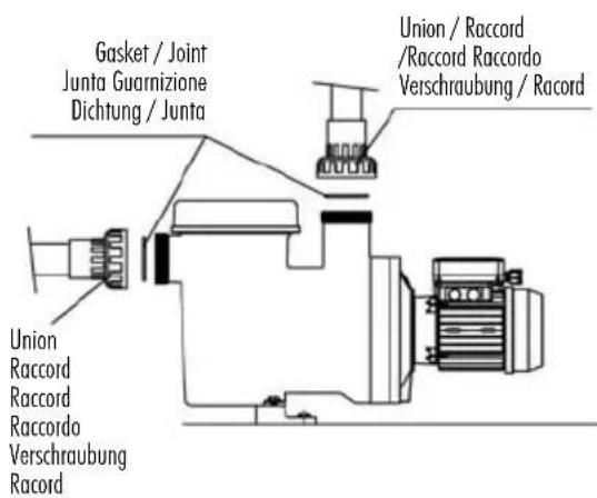
- To connect the piping, glue the pipes and the connectors, supplied together with the pump; the fitting connections to the suction and return ports on the pump are threaded and include seals to prevent water loss (Fig. 2).
- Fit the return pipes completely perpendicular and centred in relation to the port to be connected to prevent the pump and the pipe from being subjected to external stress that, apart from making fitting difficult, could break them (Fig. 2).
- Fit the suction piping on a slight 2% slope towards the pump to avoid the formation of air pockets (Fig. 2).
- To ensure the pump works correctly, prime the pump pre-filter until water rises up through the suction pipe (Fig. 3).

LOCATION
- Fit the pump underneath the water level in the pool to improve pump performance.
- Where a self-priming pump is to be fitted above the water level, the pressure differential to the pump suction should not be higher than 0.02 MPa (2 mH2O), ensuring that the suction pipe is as short as possible as a longer pipe would increase suction time and the installation's load losses.
- Make sure that the pump is safe from possible flooding and receives dry ventilation.

ELECTRICAL INSTALLATION

- It is essential that you use a multiple disconnection device with a space of at least 3 mm between surfaces to disconnect the equipment from the electrical current.
- Use a rigid cable to connect to the mains. If you use a flexible cable to connect to the mains, it must have cable lugs to connect to the terminals of the pump motor.
- The equipment should be connected to an alternating current supply (see data on the pump's plate) with earth connection, protected by a residual current device (RCD) having a rated residual operating current not exceeding 30 mA.
- Adjust the value of the thermal relay appropriately depending on the pump current.
- Before connecting the motor, check the type of fuse required.
- Check the correct layout and connection of the earthing cable in the equipment.
- Respect the electrical installation and connection conditions. Failure to do so may lead to the pump manufacturer declining all responsibility and rendering the guarantee null and void.
- Special regulations may exist for the installation.
- Unsuitable mains connections involve the risk of electrocution.
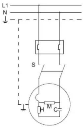
For pumps with a single-phase motor:
• Thermal protection is incorporated.
- Use a motor guard with magneto-thermal protection.
- The adjustment data for the thermal relay is to be used as a guideline, as the motor is already fitted with protection.
- For 230 V, use a H07 RN-F3 type connection sleeve with a cable section that adapts to the power of the motor and to the length of the cable.
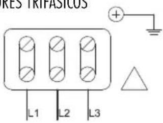
For pumps with a three-phase motor:
- Use a motor guard with magneto-thermal protection.
- Protect the pump against overloads with a cut-off switch for the motor.
- Adjust the thermal value according to the thermal protection table. For the connection (3 x 230 V network), use the protection with the highest indicated value. For the connection Y (3 x 400 V network), use the protection with the lowest indicated value.
- Connect the lowest voltage at and the highest at Y for voltage intervals other than 230/400 V; 400/690 V.
- For AC, use a H07 RN-F3 type connection sleeve with a cable section that adapts to the power of the motor and the length of the cable.
- The mains cable may only be connected by skilled, authorised personnel.
4. START-UP INSTRUCTIONS
PRIOR TO START-UP

- Carry out the following operations before starting the pump:
- Remove the pre-filter cap by unscrewing the nut holding it in place (Fig. 5).
- Fill the pump with water through the pre-filter until it rises up through the suction pipe.
- Should the basket be removed during these operations, do not forget to replace it to prevent large particles from entering the pump that could block it.
-
Check that the mains voltage and frequency correspond with those indicated on the pump characteristics plate.
-
Fit the pre-filter cap and screw on tight, not forgetting to fit the seal in its housing (Fig. 5).
- The pumps must not be run without the pre-filter having first been filled with water. Where this is not the case, the mechanical gasket may be damaged, leading to a loss of water.
- Check that the motor rotates in the correct direction by means of the fan located at the back of the motor that can be seen through the view hole on the fan cover (Fig. 6).

START-UP

- Open all the valves and connect the motor.
- Activate the self-priming and wait a reasonable time for this to be completed.
5. MAINTENANCE

- For regular control:
- Check that the mechanical parts are tightly secured and check the condition of the screws supporting the machine.
- Clean the pre-filter basket regularly to avoid drops in pressure. To prevent the basket from breaking, do not hit it during the cleaning process.
- The pump should be checked every 100 hours of operation or less, depending on the level of cleanliness of the water.
-
Check the temperature of the machine and the electric motor. In the event of a fault, stop the machine immediately and contact the nearest Technical Assistance Service.
-
Check for machine vibrations. In the event of a fault, stop the machine immediately and contact the nearest Technical Assistance Service.
- Should the pump stop, check that consumption of the running motor in amperes is equal to or below that indicated on the manufacturer's characteristics plate. If this information is available, contact the nearest Technical Assistance Service.
- Empty the pump if it is to remain at a standstill for a certain length of time, especially in cold countries where there is a risk of freezing.
- Remove the purge cap (10) to empty the pump.
- Every time the pre-filter is opened, clean the seal and its seating of any impurities to ensure airtightness when the cap is closed (Fig. 5).
- Pump components that, due to their normal use, suffer wear and/or tear must be regularly replaced to ensure good pump performance. The following table shows the perishables and/or consumables used in the pump and their estimated working life.
| COMPONENT DESCRIPTION ESTIMATED WORKING LIFE | |
| 0 rings and general seals 1 year | |
| Mechanical seal 1 year | |
| Bearings 1 year | |
The estimated working life of the parts above has been established according to normal product use and installation conditions. Follow the instructions in the installation manual to maintain the working life of the pump.


6.REMOVAL
- The motor unit can be removed from the pump body without having to disconnect the pump's suction and return pipes.
- To remove the Motor unit from the pump body, remove the screws joining them together.
7.TROUBLESHOOTING
- The pump is not primed 4. The pump will not start
- The pump releases only a small flow of water
-
The pump makes a noise 6. The motor is stopped
-
The motor is making a noise but will not start
| 1 2 | 3 4 | 5 6 | CAUSES | SOLUTIONS | |
| • | • | Air entering the suction pipe | |||
| • | Filter cap badly sealed Clean the filter cap and check the condition of the rubber seal | ||||
| • | • | Inverted motor turning | |||
| •• | • | Wrong voltage | |||
| • | Pre-filter blocked | ||||
| • | Load loss in the installation | ||||
| • | Pump incorrectly secured | ||||
| • | Motor blocked |
| 1 | 2 | 3 | 4 | 5 | 6 | CAU | SES | S | OLUTIONS | |
| • | Increased temperature in the terminal box due to electric arc | Check the terminal box connections | ||||||||
| • | The thermal protection trips Connect | the cables correctly to the terminal boxes | ||||||||
| • | Incorrect terminal box connections | Tighten the cable correctly to the terminal / Adapt the size of the cable connection to the terminal box |
IMPORTANT
natural_image
Technical line drawing of a mechanical assembly with no visible text or symbolsnatural_image
Technical line drawing of a mechanical component embedded in a fluid medium (no text or symbols)Fig. 1
CORRECT / CORRECT / CORRECTO
CORRETTO / RICHTIG / CORRECTO
INCORRECT / INCORRECT / INCORRECTO
NON CORRETTO / FALSCH / INCORRECTO

Fig. 2

Fig. 3
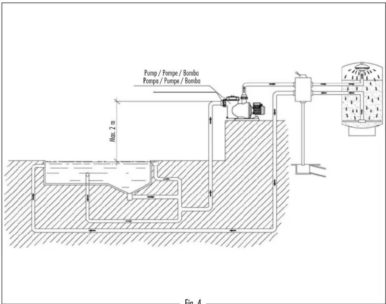


Fig. 6
SINGLE PHASE MOTORS / MOTEURS MONOPHASES MOTORES MONOFÁSICOS / MOTORI MONOFASE EINPHASIGE MOTOREN / MOTORES MONOFASICOS

THREE PHASE MOTORS / MOTEURS TRIPHASES MOTORES TRIFÁSICOS / MOTORI TRIFASE DREINPHASE MOTOREN / MOTORES TRIFASICOS

SINGLE PHASE / MONOPHASES MONOFÁSICOS / MONOFASE EINPHASIG / MONOFASICOS
THREE PHASE / TRIPHASES TRIFÁSICOS / TRIFASE DREINPHASIG / TRIFASICOS

Cod. 05085-0008 / Rev. 7
- We reserve the right to change all or part of the features of the articles or contents of this document, without prior notice.
- Nous nous réservons le droit de modifier totalement ou en partie les caractéristiques de nos articles ou le contenu de ce document sans préavis.
- Nos reservamos el derecho de cambiar total o parcialmente las características de nuestros artículos o contenido de este documento sin previo aviso.
- Ci riserviamo il diritto di cambiare totalmente o parzialmente le caratteristiche tecniche dei nostri prodotti ed il contenuto di questo documento senza nessum preavviso.
- Wir behalten uns das recht vor, die merkmale unserer produkte und den inhalt dieser beschreibung ohne vorherige unkündigung ganz oder teilweise zu ändern.
- Reservamo-nos no direito de alterar, total ou parcialmente características dos nossos artigos ou o conteúdo deste documento sem aviso prévio.
- 1.GENERAL SAFETY INSTRUCTIONS
- 2.GENERAL SAFETY REGULATIONS
- GENERAL
- WARNINGS DURING INSTALLATION AND ASSEMBLY WORK
- WARNINGS DURING START-UP
- WARNINGS DURING ASSEMBLY AND MAINTENANCE WORK
- INSTALLATION AND ASSEMBLY
- PIPING
- LOCATION
- ELECTRICAL INSTALLATION
- START-UP INSTRUCTIONS
- PRIOR TO START-UP
- START-UP
- MAINTENANCE
- 6.REMOVAL
- 7.TROUBLESHOOTING
- IMPORTANT
- Cod. 05085-0008 / Rev. 7
Brand : ASTRALPOOL
Model : ARAL C 1500
Category : Pump