ST 725 - Measuring equipment BENNING - Free user manual and instructions
Find the device manual for free ST 725 BENNING in PDF.

User questions about ST 725 BENNING
0 question about this device. Answer the ones you know or ask your own.
Ask a new question about this device
Download the instructions for your Measuring equipment in PDF format for free! Find your manual ST 725 - BENNING and take your electronic device back in hand. On this page are published all the documents necessary for the use of your device. ST 725 by BENNING.
USER MANUAL ST 725 BENNING
30 mA) Fig. 8a: Testing of permanently installed RCDs (I
Operating instructions BENNING ST 725 Appliance tester for safety-related testing of portable electrical devices and equipment - testing of electrical appliances according to DIN VDE 0701-0702, DGUV Regulation 3, NEN 3140 - testing of cable reels, multiple distributors and IEC power cords - testing of three-phase electrical appliances by means of optional measuring adapters - tripping time measurement of permanently installed RCDs and portable RCDs (PRCDs) - voltage measurement on external shock-proof socket Table of contents
3. Scope of delivery and optional accessories
7.1 Protective conductor resistance
7.2 Insulating resistance
7.3 Protective conductor current and contact current by means of alternative leakage
current measurement method
7.4 Protective conductor current (differential current measurement method)
7.5 Contact current (direct measurement method)
7.7 Tripping time measurement of RCDs
7.8 Protective conductor current (direct measurement method) (optional measuring
adapters 044140 or 044141)
7.9 Voltage measuring on external shock-proof socket
7.10 Limiting values according to DIN VDE 0701-0702
8. Measuring with the BENNING ST 725
8.1 Preparations for measuring
8.4 Testing procedure
9. Testing of electrical devices / equipment according to DIN VDE 0701-0702 and ÖVE/
9.1 Testing of devices of protection class I
9.2 Testing of devices of protection class II/ III
9.3.1 Testing of IEC power cords (IEC adapter cables)
9.3.2 Testing of cable reels, multiple distributors and extension cables
9.4 Testing of three-phase appliances
9.5 Testing of 30 mA RCDs
9.5.1 Testing of permanently installed RCDs
9.5.2 Testing of portable RCDs (PRCDs)
10. Measured value memory
10.1 Storing measured values
10.2 Calling measured values
10.3 Deleting the measured value memory
10.4 Reading out the measured value memory via the USB interface
10.5 Printing measured values
11.3 Battery replacement
11.4 Fuse replacement
11.7 Environmental note
These operating instructions are intended for - qualied electricians, competent persons and - electrotechnically trained persons The BENNING ST 725 is intended for making measurements in dry environment (More details07/ 2018 BENNING ST 725
in Section 6. “Ambient conditions”). The following symbols are used in these operating instructions and on the BENNING ST 725:
Warning of electrical danger! Indicates instructions which must be followed to avoid danger to persons.
Important, comply with the documentation! The symbol indicates that the information provided in the operating instructions must be complied with in order to avoid risks. This symbol on the BENNING ST 725 means that the BENNING ST 725 complies with the EU directives. This symbol appears on the display to indicate discharged batteries. As soon as the battery symbol ashes, immediately replace the batteries by new ones. Charged batteries are also required for measuring in mains operating mode.
(AC) Alternating voltage or current. Ground (Voltage against ground).
The instrument is built and tested in accordance with DIN EN 61557-16 (VDE 0413-16) DIN EN 61010-1 (VDE 0411-1) DIN EN 61010-2-030 (VDE 0411-2-030) DIN EN 61557-1, -2, -4, -10 and -16 (VDE 0413-1, -2, -4, -10 and -16) and has left the factory in perfectly safe technical state. To maintain this state and ensure safe operation of the appliance tester, the user must observe the notes and warnings given in these instructions at all times. Improper handling and non observance of the warnings might involve severe injuries or danger to life.
WARNING! Be careful when working with bare conductors or main line carrier! Contact with live conductors will cause an electric shock!
The BENNING ST 725 may be used only in power circuits within the overvoltage category II with a conductor for 300 V AC max. to earth. Remember that work on electrical components of all kinds is dangerous. Even low voltages of 30 V AC and 60 V DC may be dangerous to human life.
The device must be connected to a single-phase mains with 230 V, 50 Hz, pre-fuse 16 A only. Please make sure not to exceed the maximum breaking capacity/ lamp load of the test socket of the BENNING ST 725 (see chapters 7.4 and 7.5). Exceeding the values might cause tripping of the fuses and damaging of the BENNING ST 725. Damages due to overload are excluded from possible warranty claims.
Do not carry out repeated protective conductor or contact current measurements with a measuring duration of 2 x 5 minutes at test objects with high current consumption (16 A). Repeated measurements at maximum load (16 A) might heat up the inside of the device and thus also its surface.
The protective conductor resistance measurement might be distorted by impedances connected in parallel of additional operating circuits and by transient currents. Measurements of the protective conductor resistance and of the insulating resistance must be carried out at idle system parts only.
Before starting the appliance tester up, always check it for signs of damage.07/ 2018 BENNING ST 725
Should it appear that safe operation of the appliance tester is no longer possible, it should be shut down immediately and secured to prevent it being switched on accidentally. It may be assumed that safe operation is no longer possible: - if the instrument show visible signs of damage - if the appliance tester no longer functions - after long periods of storage under unfavourable conditions - after being subjected to rough transport - the device is exposed to moisture.
In order to prevent danger - do not touch the bare measuring probe tips of the measuring leads, - plug the leads into the correspondingly marked jacks at the measuring instrument
Maintenance: Do not open the tester, because it contains no components which can be repaired by the user. Repair and service must be carried out by qualified personnel only!
Cleaning: Regularly wipe the housing by means of a dry cloth and cleaning agent. Do not use any polishing agents or solvents!
3. Scope of delivery and optional accessories
The scope of delivery for the BENNING ST 725 comprises:
3.1 One BENNING ST 725,
3.2 One test lead with alligator clip,
3.3 One IEC power cord (IEC adapter cable)
3.6 One USB connecting cable (A plug to Micro-B plug),
3.7 Six 1.5-V-batteries/ type AA (IEC LR6) fitted in the unit as initial equipment,
3.8 One operating manual
3.9 One CD-ROM with download/driver software, multilingual operating manual and
information material Parts subject to wear: - The BENNING ST 725 is provided with two fuses for overload protection: two fuses with a nominal current of 16 A, 250 V, F, breaking capacity ≥ 500 A, D = 5 mm, L = 20 mm (part no. 10019440) - The BENNING ST 725 is supplied by six 1.5 V batteries/ type AA (IEC LR6). Note on optional accessories: - Portable printer BENNING PT 1 for printing test records rapidly on site, direct thermal printing process, incl. Mains supply unit and rechargeable Ni/MH battery pack (044150) - Rolls of thermographic paper (20 pieces), roll width / length: 58 mm /13 m (044151) - Test badges "next test", 300 pieces (756212) Passive measuring adapters: - Measuring adapter for single- and three-phase loads (passive, without mains voltage- dependent switching devices) for R
, R ISO (insulating resistance) and I
(alternative leakage current) measurements: - 16 A CEE coupling (3-pin) - 16 A shock-proof plug (044143) - 32 A CEE coupling (3-pin) - 16 A shock-proof plug (044144) - 16 A + 32 A CEE coupling (5-pin) + 16 A CEE coupling (3-pin) - 16 A shock-proof plug (044147) - 16 A CEE coupling (5-pin) - shock-proof plug (044122) - 32 A CEE coupling (5-pin) - shock-proof plug (044123) Active measuring adapters: - Measuring adapter for three-phase loads (active, with mains voltage-dependent switching devices) for R
measurements (direct measurement) under operating conditions: - 16 A CEE adapter (5-pin), active (044140) - 32 A CEE adapter(5-pin), active (044141) As an alternative: - BENNING CM 9 leakage current clamp for measuring the differential current, protective conductor current and load current of single-phase and three-phase loads (044065) - Measuring adapter for BENNING CM 9 leakage current clamp, conductors led through individually, with double insulation: - 16 A shock-proof coupling - 16 A shock-proof plug (044131) - 16 A CEE coupling (5-pin) - CEE plug (5-pin) (044127)07/ 2018 BENNING ST 725
- 32 A CEE coupling (5-pin) - CEE plug (5-pin) (044128) - Test certificate forms for "Testing of electrical devices" are available for download free of charge at www.benning.de See gure 10: Optional accessories
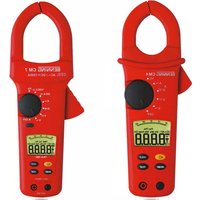
See gure 1: Appliance front face See gure 2: Top side of the device The display and operator control elements specied in Fig. 1 and 2 are designated as follows:
Test socket, for connecting the device to be tested,
-key, testing of devices of protection class I (devices with protective conductor and accessible conductive parts which are connected to the protective conductor),
-key, testing of devices of protection class II (shock-proof devices without protective conductor and with accessible conductive parts) and testing of devices of protection class III (safety extra-low voltage),
-key, testing the protective conductor current (differential measurement) or contact current (direct measurement) under operating conditions (test sample is supplied with mains voltage)
-key, reducing the testing voltage to 250 V
for measuring the insulating resistance
-key, testing of three-phase devices under operating conditions (044140, 044141)
Digital display, indicates the test progress and individual measuring results,
4 mm test socket, for connecting the test lead with alligator clip
IEC connector, for connecting the IEC power cord
Mains connection socket, for connecting the mains voltage (230 V, 50 Hz), for voltage measurement at external shock-proof socket or for connecting the measuring signal cable of the measuring adapter (16 A CEE adapter, three-phase, active (044140)/ 32 A CEE adapter, threephase, active (044141))
-key, for printing the displayed or stored measured values by means of the printer BENNING PT 1
USB interface (Micro-B socket), for connection of the USB connecting cable
5. General information
The BENNING ST 725 is intended for electrical safety tests according to DIN VDE 0701-0702, DGUV Regulation 3 (former BGV A3) and ÖVE/ ÖNORM E8701. Automatically, the BENNING ST 725 veries the type of the connected test object and informs the user in case of incorrect selection of the testing procedure [
]: preset limiting values and measuring results with "pass/ fail" information make it easier to evaluate the test. - At full battery capacity, the BENNING ST 725 allows to carry out approx. 2,500 device tests. - Appliance dimensions: (L x W x H) = 270 x 115 x 55 mm - Appliance weight: 1100 g
6. Ambient conditions
- The BENNING ST 725 is intended for making measurements in dry environment. - Maximum barometric elevation for making measurements: 2000 m, - Over voltage category/ setting category: IEC 61010-1 → 300 V category II, - Contamination class: 2, - Protection class: IP 40 (DIN VDE 0470-1 IEC/ EN 60529) IP 40 means: Protection against access to dangerous parts and protection against solid impurities of a diameter > 1 mm, (4 - first index). No protection against water, (0 - second index).
- Operating temperature and relative humidity: For operating temperatures from 0 °C to 30 °C: relative humidity less than 80 % For operating temperatures from 31 °C to 40 °C: relative humidity less than 75 % - Storage temperature: The BENNING ST 725 can be stored at any temperature within the range of - 25 °C to + 65 °C (relative humidity from 0 to 80 %). The battery should be removed from the instrument for storage.
7. Electrical specifications
Note: The measuring accuracy is specied as the sum of - a relative fraction of the measured value and - a number of digits (i.e. counting steps of the last digit). This specied measuring accuracy is valid for temperatures within the range of 18 °C to 28 °C and relative humidity lower than 80 %.07/ 2018 BENNING ST 725
7.1 Protective conductor resistance
Measuring range Resolution Measuring accuracy
7.2 Insulating resistance
Measuring range Resolution Measuring accuracy
7.3 Protective conductor current and contact current by means of alternative leakage
current measurement method Measuring range Resolution Measuring accuracy
0.25 mA - 19.99 mA 0.01 mA 5 % ± 2 digits
Testing voltage: 40 V
7.4 Protective conductor current (differential current measurement method)
Measuring range Resolution Measuring accuracy
0.25 mA - 19.99 mA 0.01 mA 5 % ± 2 digits
Nominal voltage: 230 V ± 10 % (as mains feed-in) Rated current: 16 A Max. breaking capacity: 3000 VA Max. lamp load: 1000 W Max. measuring duration: 30 seconds Preset limiting value: 3.5 mA (protection class I) Resistance to external voltages: max. 276 V For non-sinusoidal current supply, an additional error has to be considered: crest factor of > 1.4 to 2.0, additional error + 0.4 % External magnetic elds might inuence the measuring result additionally.
7.5 Contact current (direct measurement method)
Measuring range Resolution Measuring accuracy
0.1 mA - 1.99 mA 0.01 mA 5 % ± 2 digits
Nominal voltage: 230 V ± 10 % (as mains feed-in) Rated current: 16 A Max. breaking capacity: 3000 VA Max. lamp load: 1000 W Max. measuring duration: 30 seconds Preset limiting value: 0.5 mA (protection class II)07/ 2018 BENNING ST 725
Resistance to external voltages: max. 276 V For non-sinusoidal current supply, an additional error has to be considered: crest factor of > 1.4 to 2.0, additional error + 3.1 %
- measurement of the protective conductor resistance according to 7.1 - measurement of the insulating resistance according to 7.2 - line break testing of the external conductor (L) and the neutral conductor (N) - short-circuit testing of the external conductor (L) and the neutral conductor (N)
7.7 Tripping time measurement of RCDs
Measuring range Resolution Measuring accuracy 10 ms - 500 ms 1 ms 5 % ± 2 digits Testing current / polarity: 30 mA sinussoidal/0° and 180° 150 mA sinussoidal /0° and 180° Preset limiting value: 200 ms (30 mA), 40 ms (150 mA)
7.8 Protective conductor current (direct measurement method) (optional measuring
Nominal voltage: 3 x 400 V ± 10 % (as mains feed-in) Rated current: 16 A or 32 A Preset limiting value:
7.9 Voltage measuring on external shock-proof socket
1 V 5 % ± 2 digits 300 V Display: - voltage between the external conductor (L) and the neutral conductor (N) - voltage between the external conductor (L) and the ground conductor (PE) - voltage between the neutral conductor (N) and the ground conductor (PE)
7.10 Limiting values according to DIN VDE 0701-0702 and ÖVE/ ÖNORM E 8701-1
Note: Limiting values preset in bold are stored in the BENNING ST 725. Protection class I Protection class II, III Line test Protective conductor resistance
For cords with rated current ≤ 16 A: ≤ 0.3 Ω up to a length of 5 m, per further 7.5 m: additional 0.1 Ω, max. 1 Ω, For cords with higher rated cur- rents the calculated ohmic resistance value applies. ≤ 0,3 Ω (see protection class I) Insulating resistance
ISO ≥ 1 MΩ ≥ 2 MΩ for proving safe disconnec- tion (transformer) ≥ 0.3 MΩ for devices with heating element ≥ 2 MΩ (protection class II), ≥ 0.25 MΩ (protection class III) ≥ 1 MΩ Protective conductor current
/ I LEAK ≤ 3.5 mA on conductive parts with PE con- nection 1 mA/ kW for devices with heating elements P > 3.5 kW Contact current
/ I LEAK ≤ 0.5 mA on conductive parts without PE connection ≤ 0.5 mA on conductive parts without PE connection07/ 2018 BENNING ST 725
8. Measuring with the BENNING ST 725
8.1 Preparations for measuring
Operate and store the BENNING ST 725 only at the specied storage and operating tempera- tures conditions. Do not permanently expose the device to sunlight. - Check rated voltage and rated current details specified on the safety measuring leads. - Strong sources of interference in the vicinity of the BENNING ST 725 might lead to unstable readings and measuring errors.
Before starting the BENNING ST 725, always check the device, the lines and the test object for damages.
Please make sure not to exceed the maximum breaking capacity/ lamp load of the test socket of the BENNING ST 725 (see chapters 7.4 and 7.5). Exceeding the values might cause tripping of the fuses and damaging of the BENNING ST 725. Damages due to overload are excluded from possible warranty claims.
The plug of the mains connection cable can be connected with the socket K of the BENNING ST 725 in one position only (see white mark). Do not exert force to the plug of the mains connection cable in order to avoid damaging of the BENNING ST 725.
Before starting the test, switch the test object on (mains switch ON). If the BENNING ST 725 is connected to the mains voltage, the test object will be supplied with mains voltage during the protective conductor/ contact current measurement. During measurement, check the test object for proper function- ing!
At the beginning of the test it has to be checked whether the selected testing procedure complies with the protection class of the connected test object.
8.2 Switching the BENNING ST 725 ON/ OFF
- Press and hold the keys
for approx. 3 seconds to switch the BENNING ST 725 on. Acoustic signals confirm that the device is switched on. Press the keys again to switch the device off. - After approx. 2 minutes, the BENNING ST 725 switches off automatically (APO, Auto Power-Off). It switches on again when the keys
are pressed. An acoustic signal indicates that the device has switched off automatically.
8.3 Testing the mains voltage on external shock-proof socket
- Connect the mains connection cable to the mains connection socket K of the BENNING ST 725. - Connect the shock-proof plug to the shock-proof socket to be tested. With the mains voltage being applied, the voltage measurement will start automatically. - Depending on the external conductor position (right or left) of the shock-proof socket, the voltage potentials between the connecting terminals L, N and PE will be shown on the display for approx. 3 seconds.
- If the voltage potentials are within the following limiting values, there will be a next to the "LN", "LE" and "NE" symbols.07/ 2018 BENNING ST 725
Only the voltage potentials between the individual connections L, N and PE are measured. The measurement does not provide any information on the proper installation of the shock-proof socket. There will be no warning in case of a dangerous contact voltage of the PE conductor! The BENNING ST 725 must not be permanently connected to the mains voltage! - After approx. 3 seconds, the BENNING ST 725 automatically switches to stand-by mode. See gure 3: Voltage measurement on external shock-proof socket
8.4 Testing procedure
The BENNING ST 725 is intended for electrical safety tests according to DIN VDE 0701-0702 and ÖVE/ ÖNORM E 8701. Please refer to the current version of the standards for detailed information concerning the tests and limiting values. Automatically, the BENNING ST 725 veries the type of the connected test object and informs the user in case of incorrect preselection of the testing procedure [
Note: - The BENNING ST 725 can be used for tests in battery operating mode and in mains operating mode with connection of a mains voltage of 230 V. In battery operating mode, it has to be observed that the protective conductor current and contact current measurement is carried out by means of the alternative leakage current measurement method. This method is appropriate for test objects which do not contain any mains voltage-dependent switching elements (e.g. mains supply units). - If the internal structure of the test object is not known or if it contains mains voltage- dependent switching elements, the test has to be carried out in mains operating mode with connection of a mains voltage of 230 V. As soon as the BENNING ST 725 is supplied with mains voltage via the jack K, the protective conductor current/ contact current measurement will be carried out automatically by means of the differential current/ direct measurement method under operating conditions of the test object. - The testing voltage for insulating resistance measurement is preset to 500 V
according to the applicable standard. For test objects with integrated overvoltage arresters and for electronic devices for which there are objections regarding a testing voltage of 500 V
, the testing voltage can be reduced to 250 V
by means of the -key
9. Testing of electrical devices / equipment according to DIN VDE 0701-0702 and ÖVE/
Prior to test, a visual inspection of the test object has to be carried out. In case of possible damages, the test must be stopped.
9.1 Testing of devices of protection class I
Testing of devices with protective conductor and accessible conductive parts which are con- nected to the protective conductor. - Connect the test object to the test socket
of the BENNING ST 725. - Plug the 4 mm safety plug of the test lead with alligator clip into the 4 mm safety socket
and establish a connection with a metal part of the test object. - For mains operating mode (protective conductor current by means of differential current measurement method, test object in operation!): Connect the plug of the mains connection cable with the socket K and the shock-proof plug with a protected shock-proof socket (230 V, 50 Hz, 16 A). - If necessary, the testing voltage of the R ISO (insulating resistance) measurement can be reduced to 250 V
by means of the -key
. The selected testing voltage is briefly shown on the display
. Press the key again to switch back to the preset testing voltage of 500 V
to start the automatic testing procedure. - The test starts with measuring the protective conductor resistance R
is higher than 1 Ω, the measured value of R
will be shown on the display and a will appear next to the R
symbol. "FAIL" appears on the display to confirm that the measurement has been stopped.07/ 2018 BENNING ST 725
is higher than the admissible limiting value (≤ 0.3 Ω up to a length of 5 m) but lower than 1 Ω, the measured value will be displayed without a rating, the “tAble” symbol will appear on the display and the test procedure will be stopped. The responsible testing staff determines by means of the limiting value table (see section 7.10 or the table on the rear of the BENNING ST 725) and by means of the line length of the test object whether the displayed measured value is acceptable or not. Press the -key
to give the measured value a positive rating and a will be displayed next to the R
symbol. The test procedure will be continued. Press the
to give the measured value a negative rating and a will be displayed next to the R
symbol. "FAIL" appears on the display to confirm that the measurement has been stopped. - If R
is lower than the admissible limiting value, the measured value of R
is shown and a appears next to the R
measurement is carried out again with reversed polarity and the highest measured value of both measurements will be displayed. After the R
test has been passed, the test of the insulating resistance is started. - If "Lo LOAD" is shown on the display, please check whether the test object is switched on. - Press the key
to continue the testing procedure in case of the load being too low (R L-N
LOAD ) > 16 A) of the test object. There might be danger of a short-circuit or of an earth fault. Check whether there is a short-circuit between the external conductor (L) and neutral conductor (N) of the test object. - If there is no short-circuit, you can continue with the testing procedure by pressing the key
- If the insulating resistance R ISO is higher than the admissible limiting value, a appears next to the R ISO symbol.07/ 2018 BENNING ST 725
BENNING ST 725 in mains operating mode: - The BENNING ST 725 interrupts the testing procedure after the R ISO (insulating resistance) measurement and requests the user to switch the mains voltage of 230 V to the test socket
by showing a flashing "I LEAK " symbol. Make sure that the test sample is protected and press the -key
to measure the protective conductor current by means of the differential current measurement method. - The protective conductor current measurement (differential current measurement method) only starts as soon as the mains voltage is correct applied. step 1 of 2: - After a measuring time of 5 seconds or by pressing the key
, mains polarity will be reversed and the protective conductor current will be measured with reversed mains voltage ("L/N" - "N/L"). The highest measured value of both measurements will be displayed. (step 2 of 2) step 2 of 2: - If the protective conductor current is lower than the admissible limiting value, a will be shown next to the I LEAK symbol. - The overall test is considered to be passed, if "PASS" is shown on the display. As an alternative: BENNING ST 725 in battery operating mode (without mains supply): - Similarly, a will be shown next to the I
symbol, if the protective conductor current I
(al- ternative leakage current measurement method) is lower than the admissible limiting value. - The test is considered to be passed, if "PASS" is shown on the display. See gure 4: Testing of devices of protection class I (devices with protective conductor and accessible conductive parts which are connected to the protective conductor) Note on measuring the protective conductor resistance: - Alternatively, the measurement of the protective conductor resistance R
can be carried out as permanent measurement (max. 2 x 90 seconds). For this purpose press the key
for approx. > 5 seconds until the symbol appears on the display. Check the connecting line of the test object by bending it over the entire length in order to detect weak points or a break of the protective conductor. The BENNING ST 725 continuously records the current measured value on the display and stores the maximum value in the memory. By pressing the key
again, the measurement is carried out with reversed polarity. Press the key
again to indicate the maximum value of R
on the display and to continue the testing procedure as described in section 9.1. Note on measuring the protective conductor current in mains operating mode: - Alternatively, the measurement of the protective conductor current I LEAK can be carried out as permanent measurement (max. 2 x 5 minutes). Press the key
for approx. > 5 seconds to start permanent measurement. After 5 minutes, the polarity of the mains voltage will be reversed automatically ("L/N" - "N/L"). By pressing the key
earlier, the mains voltage polarity reversal can be activated manually and by pressing the key
again, the07/ 2018 BENNING ST 725
measurement can be stopped. Please observe that the BENNING ST 725 is not designed for carrying out repeated permanent measurements at a high load current. If the admissible internal operating temperature is exceeded, the "StOP" and "hot" symbols will be shown on the display. In this case, the BENNING ST 725 must be disconnected from the mains and can be used again after a sufficient cooling phase. Note on measuring the contact current: - Accessible conductive parts which are not connected with the protective conductor have to be tested as described in section 9.2. For measuring the contact current (direct measurement method), the BENNING ST 725 has to be operated with a mains voltage of 230 V. - During contact current measurement by means of the direct measurement method, no part of the test object must have a connection to the earth potential. The test object must be placed onto an insulated surface. Otherwise, leakage currents to earth might influence the measuring result.
9.2 Testing of devices of protection class II
(shock-proof) and of devices of protection class III
(safety extra-low voltage) Testing of devices without protective conductor and with accessible conductive parts - Connect the test object to the test socket
of the BENNING ST 725. - Establish a connection between the 4 mm test socket
and a metal part of the test object by means of the test lead with alligator clip. - For mains operating mode (contact current by means of the direct measurement method, test object in operation!): Connect the plug of the mains connection cable with the socket K and the shock-proof plug with a protected shock-proof socket (230 V, 50 Hz, 16 A). - If necessary, the testing voltage of the R ISO (insulating resistance) measurement can be reduced to 250 V
by means of the -key
. The selected testing voltage is briefly shown on the display
. Press the key again to switch back to the preset testing voltage of 500 V
to start the automatic testing procedure. - If "Lo LOAD" is shown on the display, please check whether the test object is switched on. - Press the key
to continue the testing procedure in case of the load being too low (R L-N
LOAD ) > 16 A) of the test object. There might be danger of a m short-circuit or of an earth fault. Check whether there is a short-circuit between the external conductor (L) and neutral conductor (N) of the test object. - If there is no short-circuit, you can continue with the testing procedure by pressing the
- If the insulating resistance R ISO is higher than the admissible limiting value, a appears next to the R ISO symbol. BENNING ST 725 in mains operating mode: - The BENNING ST 725 interrupts the testing procedure after the R ISO (insulating resistance) measurement and requests the user to switch the mains voltage of 230 V to the test socket
by showing a flashing "I LEAK " symbol. Make sure that the test sample is protected and press the -key
to measure the contact current I LEAK (direct measurement method). - The contact current by means of the direct measurement method only starts as soon as the mains voltage is correct applied.07/ 2018 BENNING ST 725
step 1 of 2: - After a measuring time of 5 seconds or by pressing the key
, mains polarity will be reversed and the contact current will be measured with reversed mains voltage ("L/N" - "N/L"). The highest measured value of both measurements will be displayed. (step 2 of 2) step 2 of 2: - If the contact current is lower than the admissible limiting value, a will be shown next to the I LEAK symbol. - The overall test is considered to be passed, if "PASS" is shown on the display. As an alternative: BENNING ST 725 in battery operating mode (without mains supply): - Similarly, a will be shown next to the I
(alternative leakage current measurement method) is lower than the admissible limiting value. - The test is considered to be passed, if "PASS" is shown on the display. See gure 5: Testing of devices of protection class II (shock-proof devices without protec- tive conductor and with accessible conductive parts) and testing of devices of protection class III (safety extra-low voltage) Note on measuring the contact current in mains operating mode: - During contact current measurement by means of the direct measurement method, no part of the test object must have a connection to the earth potential. The test object must be placed onto an insulated surface. Otherwise, leakage currents to earth might influence the measuring result. - Alternatively, the measurement of the contact current I LEAK can be carried out as permanent measurement (max. 2 x 5 minutes). Press the key
for approx. > 5 seconds to start permanent measurement. After 5 minutes, the polarity of the mains voltage will be reversed automatically ("L/N" - "N/L"). By pressing the key
earlier, the mains voltage polarity reversal can be activated manually and by pressing the key
again, the measurement can be stopped. Please observe that the BENNING ST 725 is not designed for carrying out repeated permanent measurements at a high load current. If the admissible internal operating temperature is exceeded, the "StOP" and "hot" symbols will be shown on the display. In this case, the BENNING ST 725 must be disconnected from the mains and can be used again after a sufficient cooling phase. Note on measuring the insulating resistance for test objects of protection class III: - Due to the preset limiting value of 2 MΩ for test objects of protection class II, for the testing of test objects of protection class III it has to be observed that measured values between the limiting values of 2 MΩ (protection class II) and up to 0.25 MΩ (protection class III) are indicated with a next to the R ISO symbol. In this case, the measured value has to be evaluated by a competent person.07/ 2018 BENNING ST 725
The cord test can be used both for the testing of IEC power cords (device connecting cables with IEC coupler) and for the testing of cable reels, multiple distributors and extension cables.
9.3.1 Testing of IEC power cords (IEC adapter cables)
- Disconnect the plug of the mains connection cable from the socket K of the BENNING ST 725. - Connect the IEC power cord to be tested to the BENNING ST 725 by means of the IEC connector J. - Press the -key
to start the automatic testing procedure. - The test starts with measuring the protective conductor resistance R
- Depending on whether the value is higher or lower than the limiting value, a or a is indicated next to the R
The protective conductor resistance depends on the length and cross-section of the line to be tested. - If R
is higher than the admissible limiting value (≤ 0.3 Ω up to a length of 5 m) but lower than 1 Ω, the measured value will be displayed without a rating, the “tAble” symbol will appear on the display and the test procedure will be stopped. The responsible testing staff determines by means of the limiting value table (see section 7.10 or the table on the rear of the BENNING ST 725) and by means of the line length of the test object whether the displayed measured value is acceptable or not. Press the -key
to give the measured value a positive rating and a will be displayed next to the R
symbol. The test procedure will be continued. Press the
to give the measured value a negative rating and a will be displayed next to the R
symbol. "FAIL" appears on the display to confirm that the measurement has been stopped. - Please refer to Table 1 for typical resistance values of lines. Cross-section Length 1.0 mm² 1.5 mm² 2.5 mm² 5 m 0.1 Ω 0.06 Ω 0.04 Ω 10 m 0.2 Ω 0.12 Ω 0.08 Ω 25 m 0.5 Ω 0.3 Ω 0.2 Ω 50 m 1.0 Ω 0.6 Ω 0.4 Ω Table 1: Resistance values of the protective conductor depending on length and cross-section - After the R
test has been passed, the measurement of the insulating resistance is carried out automatically. - Depending on whether the value is higher or lower than the limiting value, a or a is indicated next to the R ISO symbol. - After the R ISO test has been passed, the external conductor (L) and the neutral conductor (N) are checked for line breaks and short-circuits. A passed test regarding line breaks and short-circuits is indicated by a next to the and the "Good“ symbol. - The "PASS" symbol confirms successful testing of the entire testing procedure. - If the test regarding line breaks and short-circuits has failed, one of the following symbols is indicated instead of the "Good" symbol: - "OPEN" symbol:07/ 2018 BENNING ST 725
confirms a line break of the external conductor (L) or neutral conductor (N) - "Shor" symbol: confirms a short-circuit between the external conductor (L) and the neutral conductor (N) See gure 6a: Testing of device connecting cables with IEC connector Note on measuring the protective conductor resistance: - Alternatively, the measurement of the protective conductor resistance R
can be carried out as permanent measurement (max. 2 x 90 seconds). For this purpose press the key
for approx. > 5 seconds until the
symbol appears on the display. Check the connecting line of the test object by bending it over the entire length in order to detect weak points or a break of the protective conductor. The BENNING ST 725 continuously records the current measured value on the display and stores the maximum value in the memory. By pressing the key
again, the measurement is carried out with reversed polarity. Press the key
again to indicate the maximum value of R
on the display and to continue the testing procedure as described in section 9.3.1.
9.3.2 Testing of cable reels, multiple distributors and extension cables
- Disconnect the plug of the mains connection cable from the socket
of the BENNING ST 725. - Connect the IEC power cord (IEC adapter cable) included in the scope of delivery to the IEC connector J of the BENNING ST 725. - Connect the line to be tested to the test socket
and to the shock-proof socket of the IEC power cord. - Press the key
to start the automatic testing procedure. - The further testing procedure corresponds to the testing procedure described in section
See gure 6b: Testing of lines, multiple distributors and cable reels Note on testing three-phase lines: - Disconnect the plug of the mains connection cable from the socket K of the BENNING ST 725. - The three-phase line must be connected to the test socket
of the BENNING ST 725 by means of the optional passive measuring adapters (044122, 044123 or 044147). - Plug the 4 mm safety plug of the test cable with alligator clip into the 4 mm safety socket
and establish a connection with the PE conductor of the CEE coupling.
to start the automatic test procedure for measuring R
9.4 Testing of three-phase appliances
9.4.1 Passive testing
For passive testing of three-phase appliances (test object is not running), disconnect the mains connection cable from the BENNING ST 725. Testing is carried out by means of the passive measuring adapters (044122, 044123 and 044147) with the external conductors L1, L2 and L3 of the 5-pin CEE coupling being bridged. The protective conductor current / contact current is measured by means of the alternative leakage current measurement method. Testing is carried out as described for single-phase appliances in chapter 9.1 and 9.2 (BENNING ST 725 in battery operating mode, without mains supply). See gure 7a: Testing of three-phase appliances by means of passive measuring adapters
9.4.2 Active testing
The active testing of three-phase test objects is carried out by means of the optional measuring adapters 16 A CEE, 5-pin, active (044140) or 32 A CEE, 5-pin, active (044141) under operating conditions. - Connect the CEE plug of the test object with the CEE coupling of the measuring adapter and connect the CEE plug of the measuring adapter to a protected supply mains (3 x 400 V, N, PE, 50 Hz, 16 A/ 32 A). - Connect the measuring signal cable of the measuring adapter with the mains connection socket K of the BENNING ST 725. - Connect the 4 mm safety plug of the test lead with alligator clip with the 4 mm safety socket
of the BENNING ST 725 and establish a connection with a metal part of the test object. - Make sure that the test sample is protected and switch it on. - Press the -key
to start the automatic testing procedure. - If a contact voltage is applied to the metal part of the test object, measurement will be interrupted and the following warning will be shown on the display:07/ 2018 BENNING ST 725
- Otherwise, the measurement of the protective conductor resistance (R
) will be started with automatic polarity reversal and the highest measured value of both measurements will be shown on the display. - After the R
test has been passed, the test of the protective conductor current I LEAK will be carried out as permanent measurement for max. 30 seconds. Press the -key
to finish early the measurement. - If the protective conductor current is lower than the admissible limiting value, a will be shown next to the I LEAK symbol. - The overall test is considered to be passed, if "PASS" is shown on the display. - When pressing the -key
without previously connecting the measuring adapter to the BENNING ST 725, the following warning will be shown on the display: See gure 7b: Testing of three-phase appliances by means of active measuring adapters (test object placed on insulated surface) Note: - The protective conductor current measurement is carried out using a current transformer in the protective conductor of the measuring adapter (044140 or 044141) and by means of the direct measurement method. The test object must be placed onto an insulated surface. No part of the test object must have a connection to the earth potential. Otherwise, leakage currents to earth might influence the measuring result. - If it is not possible to place the test object onto an insulated surface, the protective conductor current measurement can be carried out alternatively by means of the differential current measurement method using the BENNING CM 9 leakage current clamp (044065). For this, the test object must be put into operation by means of the optional measuring adapters (044127 or 044128) and all active conductors (L1, L2, L3 and N) must be clamped by means of the leakage current clamp. The BENNING CM 9 measures the protective conductor current by means of the differential current measurement method.
9.5 Testing of 30 mA RCDs
The BENNING ST 725 allows measuring the tripping time of permanently installed RCDs and of portable RCDs (PRCDs) with a nominal fault current of 30 mA. In the automatic test sequence, the tripping time of the one-fold nominal fault current (initial polarity of 0°/ 180°) and of the ve- fold nominal fault current (initial polarity of 0°/ 180°) is measured. By generating a fault current of 30 mA, it is proven that the RCD will trip when the nominal fault current is reached. If the limiting value of the maximum contact voltage of 50 V is exceeded, the "UB > 50 V" symbol will be shown on the display and the testing will be stopped.07/ 2018 BENNING ST 725
Before testing an RCD, the 4 mm safety plug of the test cable must be disconnected from the test socket
Measurement might be influenced by: - a possibly existing voltage between the protective conductor of the shockproof socket and earth - leakage currents in the circuit behind the RCD - further earthing equipment - equipment which is connected behind the RCD and which will cause a longer tripping time, e.g. capacitors or rotating machines
9.5.1 Testing of permanently installed RCDs
- Connect the IEC power cord to the IEC connector J of the BENNING ST 725. - Connect the shock-proof plug to a shock-proof socket which is protected by the RCD to be tested and switch on the RCD. - Press the -key
to start the RCD test. - If the "rESET" symbol is still shown on the display and the "LN" and "LE" symbols are flashing, turn the shock-proof plug in the shock-proof socket by 180° and press the -key
again to start the test. - Whenever the "rESEt" symbol appears on the display, switch the RCD on again. - The BENNING ST 725 generates a fault current of 30 mA with positive (0°) or negative (180°) initial polarity. The RCD trips and the tripping times of the one-fold nominal fault current are measured. - If the tripping time is less than the limiting value (200 ms), a will be shown next to the tripping time. - Subsequently, the BENNING ST 725 generates a fault current of 150 mA with positive (0°) or negative (180°) initial polarity. The RCD trips and the tripping times of the five-fold nominal fault current are measured. - If the tripping time is less than the limiting value (40 ms), a will be shown next to the tripping time. - The test is considered to be passed, if "PASS" is shown on the display. See gure 8a: Testing of permanently installed RCDs (I
= 30 mA) Note: - By generating a fault current of 30 mA, it is proven that the RCD will trip when the nominal fault current is reached. If the limiting value of the maximum contact voltage of 50 V is exceeded, the "UB > 50 V" symbol will be shown on the display and the testing will be stopped.
Measurement might be influenced by: - a possibly existing voltage between the protective conductor of the shockproof socket and earth - leakage currents in the circuit behind the RCD - further earthing equipment - equipment which is connected behind the RCD and which will cause a longer tripping time, e.g. capacitors or rotating machines
9.5.2 Testing of portable RCDs (PRCDs)
- Connect the plug of the mains connection cable to the jack K of the BENNING ST 725. - Connect the shock-proof plug to a 230 V shock-proof socket. With the mains voltage being applied, the voltage measurement will start automatically. - Depending on the external conductor position (right or left) of the shock-proof socket, the voltage potentials between the connecting terminals L, N and PE will be shown on the display for approx. 2 seconds.07/ 2018 BENNING ST 725
of the BENNING ST 725. - Connect the IEC power cord included in the scope of delivery to the IEC connector J of the BENNING ST 725 and connect the shock-proof plug to the portable RCD (PRCD) as shown in figure 8b. The cable outlet must point towards the display! - Press the -key
to switch the mains voltage to the test socket
. The "rCd" and "rESEt" symbols are shown on the display. - Switch the portable RCD (PRCD) on. - If the "rESET" symbol is still shown on the display and the "LN" and "LE" symbols are flashing, please verify whether the portable RCD (PRCD) is switched on. If it is switched on, turn the shock-proof plug of the IEC power cord in the portable RCD (PRCD) by 180° and start the test again.
Whenever the "rESEt" symbol appears on the display, switch the portable RCD (PRCD) on again. - The BENNING ST 725 generates a fault current of 30 mA with positive (0°) or negative (180°) initial polarity. The portable RCD (PRCD) trips and the tripping times of the one-fold nominal fault current are measured. - If the tripping time is less than the limiting value (200 ms), a will be shown next to the tripping time. - Subsequently, the BENNING ST 725 generates a fault current of 150 mA with positive (0°) or negative (180°) initial polarity. The portable RCD (PRCD) trips and the tripping times of the five-fold nominal fault current are measured. - If the tripping time is less than the limiting value (40 ms), a will be shown next to the tripping time. - The test is considered to be passed, if "PASS" is shown on the display. Note: Some portable PRCD types (e.g. PRCD-S, PRCD-K) switch off L, N and PE on all poles so that the BENNING ST 725 does not detect any connection between the IEC connector J and the test socket
. Testing of these PRCD types must be carried out according to chapter 9.5.1 "Test- ing of permanently installed RCDs" by connecting the portable RCD (PRCD) to a mains socket which is not protected by another RCD. See gure 8b: Testing of portable PRCDs (I
10. Measured value memory
The BENNING ST 725 is equipped with a measured value memory to store the measured values of 999 test objects.
10.1 Storing measured values
- As soon as the test sequence is completed and the test result is available, press the -key to store the displayed measured values to the first free storage location. The storage will be confirmed by the "STORE" symbol and the storage location number shown on the display
. The -key will be blocked until another test is carried out in order to prevent double storage. With each new storage, the storage location number will be increased automatically by one storage location. As soon as all 999 storage locations are occupied, the "FULL" symbol will be shown on the display
10.2 Calling measured values
to recall the stored measured values with the corresponding storage location number. The "RECALL" symbol is shown on the display
- Press the -key again to go to the next storage location. - Press the -key
to go to the previous storage location.
10.3 Deleting the measured value memory
to recall the stored measured values with the corresponding storage location number. The "RECALL" symbol is shown on the display
- To delete the entire measured value memory, press the -key and the -key until the counter reading is reset to zero and "no dAtA" is shown on the display
10.4 Reading out the measured value memory via the USB interface
To read out the measured values via the USB interface
, you have to install the hardware driver from the "Treiber-driver" directory on the enclosed CD-ROM and then the download program from the CD-ROM's "Programm-program" directory on your PC once. In order to download the data, please proceed as follows: - Disconnect all connection cables and test objects from the BENNING ST 725. - Connect the BENNING ST 725 to your PC by means of the USB connecting cable. - The hardware driver is installed automatically on a free COM port and confirms that the new hardware can be used. - The COM port used can be viewed by means of the Device Manager of your system. - Start the "BENNING Datalogger" program, go to "Tools", click "Refresh Ports" and select the corresponding COM port. Then, click "Download". - Press the -key of the BENNING ST 725 for approx. 5 seconds until the download takes place and the entire measured value memory is read out. - The measured values can be stored as a (*.csv) or (*.txt) file. - Click "Open" to open the measured values e.g. by means of a spreadsheet program.
10.5 Printing measured values
of the BENNING ST 725 by means of the serial printer cable. - As soon as the test sequence is completed and the test result has been called by means of the -key , it is possible to print a test document by pressing the -key
10.6 Setting the date and time
The BENNING ST 725 is equipped with an integrated real-time clock which automatically adds a date/ time stamp can be added to each storage process.07/ 2018 BENNING ST 725
To set the date and the time, carry out the following steps: - Switch the BENNING ST 725 off by pressing the -key
simultaneously. - Press and hold the -key and simultaneously press the -key
to select a date / time field. - As soon as the field is flashing, the value for that field can be set. - Press the -key or the -key to increase or decrease the value. Every change resets the field for the seconds to zero. - Switch the device off by simultaneously pressing the -key
to store the setting.
Before opening the BENNING ST 725, make sure that it is free of voltage! Electrical danger! Work on the opened BENNING ST 725 under voltage must be carried out by skilled electricians with special precautions for the prevention of accidents only! Make sure that the BENNING ST 725 is free of voltage as described below before opening the instrument: - Switch the tester off. - Remove all connecting cables from the object.
11.1 Securing the instrument
Under certain circumstances safe operation of the BENNING ST 725 is no longer ensured, for example in the case of: - Visible damage of the casing. - Incorrect measurement results. - Recognisable consequences of prolonged storage under improper conditions. - Recognisable consequences of extraordinary transportation stress. In such cases the BENNING ST 725 must be switched off immediately, disconnected from the measuring points and secured to prevent further utilisation.
Clean the exterior of the housing with a clean dry cloth (exception: special cleaning wipers). Avoid using solvents and/ or scouring agents for cleaning the instrument. It is important to make sure that the battery compartment and battery contacts are not contaminated by leaking elec- trolyte. If electrolyte contamination or white deposits occur in the area of the batteries or battery compartment, clean them too with a dry cloth.
11.3 Battery replacement
Before opening the BENNING ST 725, make sure that it is free of voltage! Electrical danger! The BENNING ST 725 is supplied by means of six 1.5 V batteries/ type AA (IEC LR6). A battery replacement (see Figure 9) is required, if the battery symbol appears on the display unit
Proceed as follows to replace the batteries: - Switch the BENNING ST 725 off. - Put the BENNING ST 725 face down and unscrew the screw of the battery compartment cover. - Lift off the battery compartment cover (in the area of the housing slots) from the bottom part of the battery compartment. - Remove the discharged batteries from the battery compartment. - Then, insert the new batteries into the battery compartment at the provided places (please observe correct polarity of the batteries). - Lock the battery compartment cover into place on the bottom part and tighten the screw. See gure 9: Battery/ fuse replacement
Make your contribution to environmental protection! Do not dispose of discharged batteries in the household garbage. Instead, take them to a collecting point for discharged batteries and special waste material. Please inform yourself in your community.07/ 2018 BENNING ST 725
11.4 Fuse replacement
Before opening the BENNING ST 725, make sure that it is free of voltage! Electrical danger! The BENNING ST 725 is protected against overload by means of two built-in fuses (16 A, 250 V, F, D = 5 mm, L = 20 mm) (10019440). Proceed as follows to replace the fuse (see Figure 9): - Switch the BENNING ST 725 off. - Put the BENNING ST 725 face down and unscrew the screw of the battery compartment cover. - Lift off the battery compartment cover (in the area of the housing slots) from the bottom part of the battery compartment. - Laterally lift one side of the defective fuse off the fuse holder by means of a slotted screwdriver. - Completely remove the defective fuse from the fuse holder. - Insert the new fuse. Only use fuses of the same nominal current, nominal voltage, nominal breaking capacity, tripping characteristic and dimensions. - Lock the battery compartment cover into place on the bottom part and tighten the screw. See gure 9: Battery/ fuse replacement
Benning guarantees compliance with the technical and accuracy specications stated in the operating manual for the rst 12 months after the delivery date. To maintain the specied ac- curacy of the measurement results, the instrument must be recalibrated at regular intervals by our factory service. We recommend a recalibration interval of one year. Send the appliance to the following address: BENNING Elektrotechnik & Elektronik GmbH & Co. KG Service Centre Robert-Bosch-Str. 20 D - 46397 Bocholt
11.7 Environmental note
At the end of the product’s useful life, please dispose of the device at collection points provided in your community.07/ 2018 BENNING ST 725