HmIPSWOPL - Weather Station Homematic IP - Free user manual and instructions
Find the device manual for free HmIPSWOPL Homematic IP in PDF.
| Product Type | Homematic IP Weather Station |
| Model | HmIPSWOPL |
| Brand | Homematic IP |
| Dimensions (W x H x D) | 54 x 108 x 65 mm |
| Weight | Approx. 200 g (incl. batteries) |
| Power Supply | 4 x 1.5 V LR6/Mignon/AA batteries |
| Battery Life | Up to 7 years (typical) |
| Protection Rating | IP20 |
| Ambient Temperature | 0 °C to 50 °C |
| Radio Frequency Band | 868.0-868.6 MHz / 869.4-869.65 MHz |
| Radio Range (Open Field) | Up to 280 m |
| Maximum Transmission Power | 10 dBm |
| Main Functions | Temperature and humidity measurement, LCD display, heating profile programming, automatic and manual modes, boost function, control via Homematic IP app |
| Display | LCD screen with backlight |
| Temperature Adjustment | Adjustable offset of ±3.5 °C |
| Anti-Theft Protection | Included, PIN code locking |
| Care and Cleaning | Soft, dry, lint-free cloth; no solvents |
| Safety | Do not open, keep out of reach of children, do not expose to moisture |
| Package Contents | 1 weather station, 1 anti-theft protection, 4 AA batteries, Danfoss adapters, support ring, instruction manual |
| System Compatibility | Homematic IP Access Point, CCU3, Homematic IP app |
| Factory Reset | Possible via configuration menu or battery manipulation |
| Warranty | Consult retailer |
Frequently Asked Questions - HmIPSWOPL Homematic IP
User questions about HmIPSWOPL Homematic IP
0 question about this device. Answer the ones you know or ask your own.
Ask a new question about this device
Download the instructions for your Weather Station in PDF format for free! Find your manual HmIPSWOPL - Homematic IP and take your electronic device back in hand. On this page are published all the documents necessary for the use of your device. HmIPSWOPL by Homematic IP.
USER MANUAL HmIPSWOPL Homematic IP
natural_image
White smartwatch with digital display showing 215°C, no visible text or symbols on device bodyLieferumfang
Anzahl Bezeichnung
Printed in Hong Kong
text_image
Diagram of a device with labeled parts and directional arrows indicating movement or flow4

text_image
4 s ↓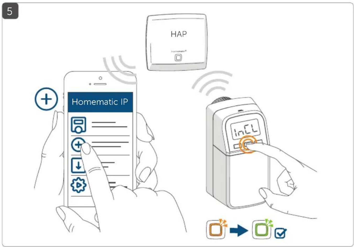
text_image
Homematic IP HAP in CL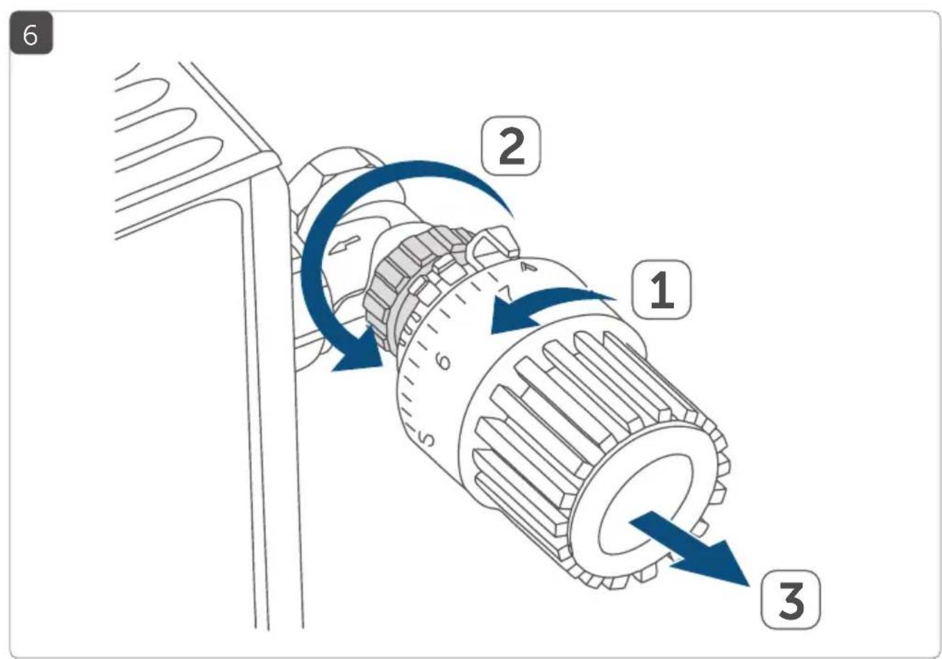
text_image
6 2 1 3
natural_image
Diagram showing a device connected to a wall-mounted panel with a piping bag attached (no text or symbols present)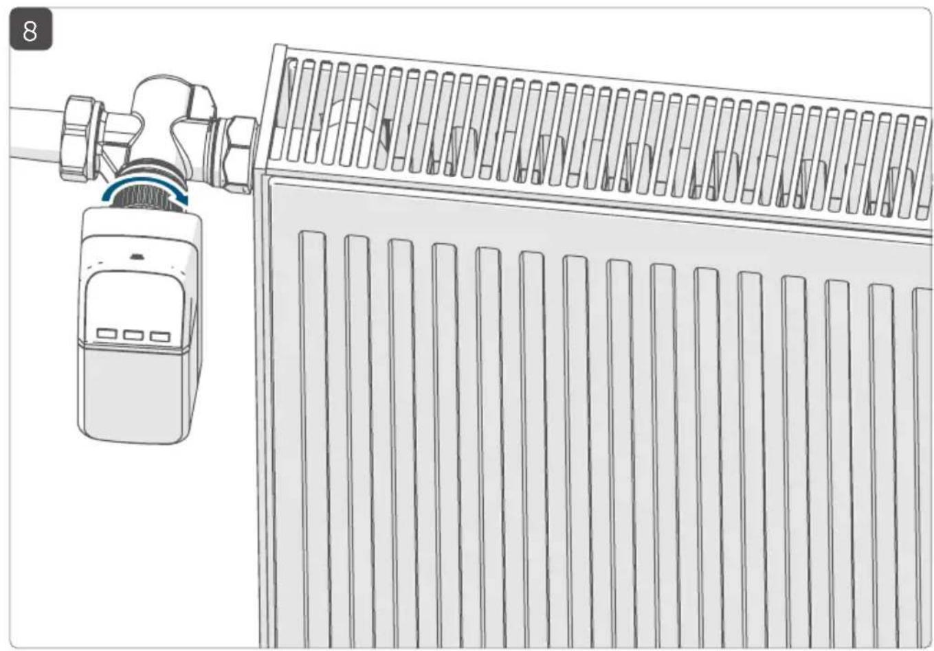
natural_image
Line drawing of a heating unit connected to a wall-mounted fan or radiator (no text or symbols)9
natural_image
Technical illustration of a mechanical component with a blue arrow pointing to a cylindrical part (no text or symbols present)10
text_image
1n5u11
text_image
2 AdRa 112
natural_image
Diagram of a mobile phone casing with two batteries, showing internal components and battery arrangement (no text or symbols)13
text_image
Diagram showing a hand inserting a battery into a mobile phone, with an inset highlighting the orange square icon.14
natural_image
Line drawing of a hand inserting a device into a device, with an inset showing a green square button (no text or symbols)Inhaltsverzeichnis
natural_image
Technical illustration of a mechanical assembly with threaded components and screwdriver (no text or symbols)Danfoss RAV
natural_image
Mechanical assembly diagram showing a screwdriver inserted into a threaded component via a tool, with blue arrows indicating motion direction (no text or symbols present)Danfoss RAVL
natural_image
Technical illustration of a mechanical assembly with two components and directional arrows indicating movement (no text or symbols)5.3 Adaptierfahrt

1 Radiator Thermostat – compact plus
1 Disassembly protection – compact
1 Danfoss adapters (RA, RAV and RAVL)
1 Support ring
1 Nut M4
1 Cylinder head screw M4 x 12 mm
4 1.5 V LR6/mignon/AA batteries
1 Operating manual
1 Supplement with safety instructions
Documentation © 2022 eQ-3 AG, Germany
All rights reserved. Translation from the original version in German. This manual may not be reproduced in any format, either in whole or in part, nor may it be duplicated or edited by electronic, mechanical or chemical means, without the written consent of the publisher.
Typographical and printing errors cannot be excluded. However, the information contained in this manual is reviewed on a regular basis and any necessary corrections will be implemented in the next edition. We accept no liability for technical or typographical errors or the consequences thereof.
All trademarks and industrial property rights are acknowledged.
Printed in Hong Kong
Changes may be made without prior notice as a result of technical advances.
157688 (web)
Version 1.0 (07/2022)
Table of contents
1 Information about this manual 42
2 Hazard information 42
3 Function and device overview 43
4 General system information 44
5 Start-up 45
5.1 Pairing 45
5.1.1 Direct pairing with a Homematic IP device 45
5.1.2 Pairing with the access point....46
5.2 Installation....48
5.2.1 Removing a thermostat 48
5.2.2 Mounting the radiator thermostat....49
5.2.3 Support ring....49
5.2.4 Adapter for Danfoss 49
5.3 Adjustment run....52
6 Configuration menu....53
7 Operation 60
8 Changing the batteries....61
9 Troubleshooting....62
9.1 Weak batteries 62
9.2 Command not confirmed....62
9.3 Duty cycle 62
9.4 Error codes and flashing sequences 63
10 Restoring factory settings 65
11 Maintenance and cleaning....66
12 General information about radio operation....66
13 Technical specifications 66
1 Information about this manual
Please read this manual carefully before operating your Homematic IP components. Keep the manual so you can refer to it at a later date if you need to. If you hand over the device to other persons for use, please hand over this manual as well.
Symbols used:

Attention!
This indicates a hazard.

Note.
This section contains important additional information!
2 Hazard information

Do not open the device. It does not contain any parts that need to be maintained by the user. In the event of an error, please have the device checked by an expert.

The device may only be operated in dry and dust-free environment and must be protected from the effects of moisture, vibrations, solar or other methods of heat radiation, cold and mechanical loads.

For safety and licensing reasons (CE), unauthorized changes and/or modifications of the device is not permitted.

The device is not a toy: do not allow children to play with it. Do not leave packaging material lying around. Plastic films/bags, pieces of polystyrene, etc. can be dangerous in the hands of a child.

We accept no liability for damage to property or personal injury caused by improper use or the failure to observe the hazard warnings. In such cases, all warranty claims are void. We accept no liability for any consequential damage.

The device is only intended for use in residential, business and commercial areas, and in small enterprises.

Please note that the room temperature control via the radiator thermostat is designed for a two-pipe heating system with one feed and return line per radiator. Use in single-pipe heating systems can lead to strong deviations in the set temperature due to fluctuations in the flow temperature.

Using the device for any purpose other than that described in this operating manual does not fall within the scope of intended use and will invalidate any warranty or liability.
3 Function and device overview
You can use the Homematic IP Radiator Thermostat to regulate the room temperature in your smart home with time control and to suit your needs. Individual temperature curves can be easily set via configurable heating profiles.
The tamper-proof housing design with sealing possibility, and the integrated operation lock with assignment of an individual PIN protect the thermostat against unwanted operation. The dismantling protection included in the scope of delivery provides additional safety.
You can directly configure the radiator thermostat on the device and adjust it to your personal needs. Alternatively, you can easily control the radiator thermostat in combination with a Homematic IP Access Point via the free smartphone app.
In combination with a Homematic IP window and door contact, the temperature is reduced automatically during ventilation.
The radiator thermostat fits all common radiator valves and is easy to mount – without having to drain any water or intervene in the heating system.
Device overview (see figure 1):
(A) Metal nut
(B) LC display
(C) Plus button
(D) Menu / boost button and device LED
(E) Minus button
(F) Battery compartment (cover)
Display overview (see figure 2):
| Overview of heating phases | |
| °C | Setpoint temperature |
| Time and date* | |
| Operating lock* | |
| Open window symbol | |
| Radio transmission | |
| Empty batteries | |
| Holiday mode* | |
| AUTO | Automatic operation* |
| MANU | Manual operation* |
| BOOST | Boost mode |
| Offset | Offset temperature* |
| Prg | Programming a heating schedule* |
| Mo Tu We Th Fr Sa Su | Days of the week |
* see see „6 Configuration menu" on page 53
4 General system information
This device is part of the Homematic IP smart home system and works with the Homematic IP radio protocol. All devices in the Homematic IP system can be configured easily and individually with a smartphone using the Homematic IP app. Alternatively, you have the option of operating Homematic IP devices via the CCU3 or in conjunction with many partner solutions. The available functions provided by the system in combination with other components are described in the Homematic IP User Guide. All current technical documents and updates are provided at www.homematic-ip.com.
5 Start-up
5.1 Pairing

Please read this entire section before starting the pairing procedure.
You can either pair the radiator thermostat directly with one or more Homematic IP devices or add the device to the Homematic IP Access Point (HmlP-HAP). After direct pairing, configuration must be done directly on the device. After pairing with the access point, configuration is done via the Homematic IP app.
5.1.1 Direct pairing with a Homematic IP device

You can directly pair the Homematic IP Radiator Thermostat with other Homematic IP Radiator Thermostats (HmIP-eTRV-CL or HmIP-eTRV-B), the Homematic IP Window / Door Contact with magnet (HmIP-SWDM (HmIP-SWDM-2) and/or the Homematic IP Wall Thermostat (HmIP-WTH-B/HmIP-WTH-B-2).

Please make sure you maintain a distance of at least 50 cm between the devices during pairing.

You can cancel the pairing procedure by briefly pressing the menu button (D). This will be indicated by the device LED (D) lighting up red.
To connect the device with another Homematic IP device, the pairing mode of both devices must be activated. To do this, proceed as follows:
- Open the battery compartments by pulling the cover (F) first downwards and then forwards (see figure 3).
- Pull the insulation strip out of the battery compartment.
- Press and hold the menu button (D) until the configuration menu opens.
-
Select "PAIR" using the plus and minus buttons (C + E).
-
Confirm your selection by briefly pressing the menu button. The device LED (D) starts to quickly flash orange (see figure 4). The pairing mode is active for 3 minutes.
- Press and hold the system button of the device you want to connect (e.g. the Homematic IP Window / Door Contact with magnet) for at least 4 seconds to activate the pairing mode. The device LED starts to flash orange (see figure 4). For further information, please refer to the operating manual of the corresponding device.
The device LED lights up green to indicate that pairing has been successful. If pairing has failed, the device LED lights up red. Please try again.

If no pairing operations are performed, pairing mode is exited automatically after 3 seconds.

If you want to add another device to the existing devices, first activate the pairing mode of the existing device and afterwards the pairing mode of the new device.

If you want to add another radiator thermostat, for example, you must first pair the new radiator thermostat to the existing radiator thermostat. Afterwards, you can pair the new radiator thermostat with the existing window / door contact.

If you are using several devices in one room, you should pair all devices with each other.
5.1.2 Pairing with the access point

If you have already paired the device with another Homematic IP device, you first have to restore the factory settings of the device before you can pair it with the Homematic IP Access Point or another CCU3 (see see „10 Restoring factory settings“ on page 65).

First set up your Homematic IP Access Point via the Homematic IP app to enable operation of other Homematic IP devices within your system. For further information, please refer to the Access Point operating manual.

You can pair the device with either the access point or the Homematic Central Control Unit CCU3. For detailed information, please refer to the Homematic IP User Guide, available for download in the download area of www.homematic-ip.com.
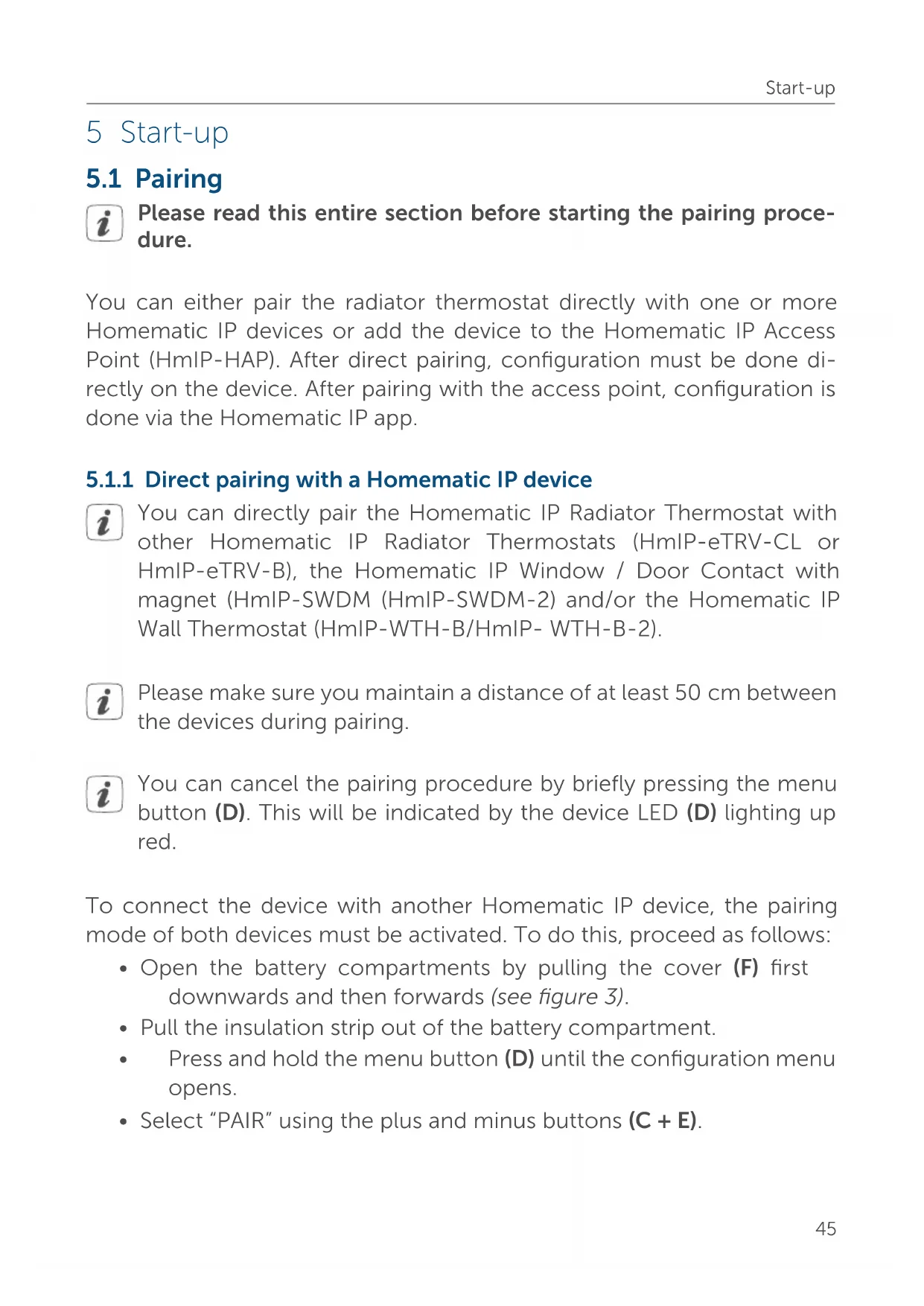
To integrate the device into your system and to enable control via the free Homematic IP app, you must first add the device to your Homematic IP Access Point.
To add the device, please proceed as follows:
- Open the Homematic IP app on your smartphone.
- Select "Add device".
- Open the battery compartments by pulling the cover (F) first downwards and then forwards (see figure 3).
- Pull both insulation strips out of the battery compartment. The pairing mode is active for 3 minutes. The device LED (D) starts to flash orange (see figure 5).

You can manually start the pairing mode for another 3 minutes by briefly pressing the system button (D). Select "INCL" and confirm your selection by briefly pressing the menu button.
- Your device will automatically appear in the Homematic IP app.
- To confirm, enter the last four digits of the device number (SG-TIN) in your app or scan the QR code. The device number can be found on the sticker supplied or attached to the device.
- Wait until pairing is completed.
-
If pairing was successful, the LED (D) lights up green. The device is now ready for use.
-
If the LED lights up red, please try again.
- In the app, give the device a name and allocate it to a room.
5.2 Installation

Please read this entire section before starting the installation.
The Homematic IP Radiator Thermostat is easy to install and can be done without draining heating water or intervening in the heating system. No special tools are required, nor does the heating have to be switched off.
The metal nut (A) attached to the radiator thermostat can be used universally and without accessories for all valves with a thread size of M30 x 1.5 mm from the most popular manufacturers. An overview and information about compatible manufacturers and valve adapters can be found at www.homematic-ip.com.
Using the adapters supplied, the device can also be installed on radiator valves type Danfoss RA, Danfoss RAV and Danfoss RAVL (see see „5.2.4 Adapter for Danfoss“ on page 49).
5.2.1 Removing a thermostat

In case of visible damage to the existing radiator, valve or heating pipes, please consult a specialist.
Remove the old thermostatic head from your radiator valve:
- Rotate the thermostatic head anti-clockwise to the maximum value (1) (see figure 6). The thermostatic head then no longer presses against the valve spindle, making it easier to remove.
The thermostatic head may be held in place in various ways:
- Union nut: Unscrew the union nut in an anticlockwise direction (2). The thermostatic head can then be removed (3).
- Snap-on fastenings: Thermostatic heads that are fastened this way can be detached by turning the fastener/union nut anti-clockwise a little. The thermostatic head can then be removed.
- Compression fitting: The thermostatic head is held in place by a mounting ring, which is held together with a screw. Loosen this screw and remove the thermostatic head from the valve.
- Threaded connection with set screw: Loosen the set screw and remove the thermostatic head.
5.2.2 Mounting the radiator thermostat
After removing the old thermostatic head, you can mount the new radiator thermostat on the heating valve:
- Place the radiator thermostat with the metal nut (A) on the heating valve (see figure 7).
- Tighten the metal nut on the radiator valve (see figure 8).

If required, you can use one of the supplied adapters for Danfoss valves (see see „5.2.4 Adapter for Danfoss“ on page 49) or the supplied support ring (see see „5.2.3 Support ring“ on page 49).
5.2.3 Support ring
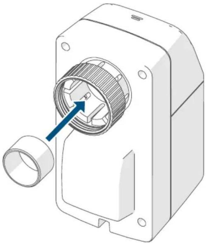
With some manufacturers' valves, the part of the valve that protrudes into the device has only a small diameter, which causes the radiator thermostat to sit more loosely on the valve. In this case, the supplied support ring should be inserted into the flange of the device before mounting (see figure 9). You can then mount the radiator thermostat again as described above.
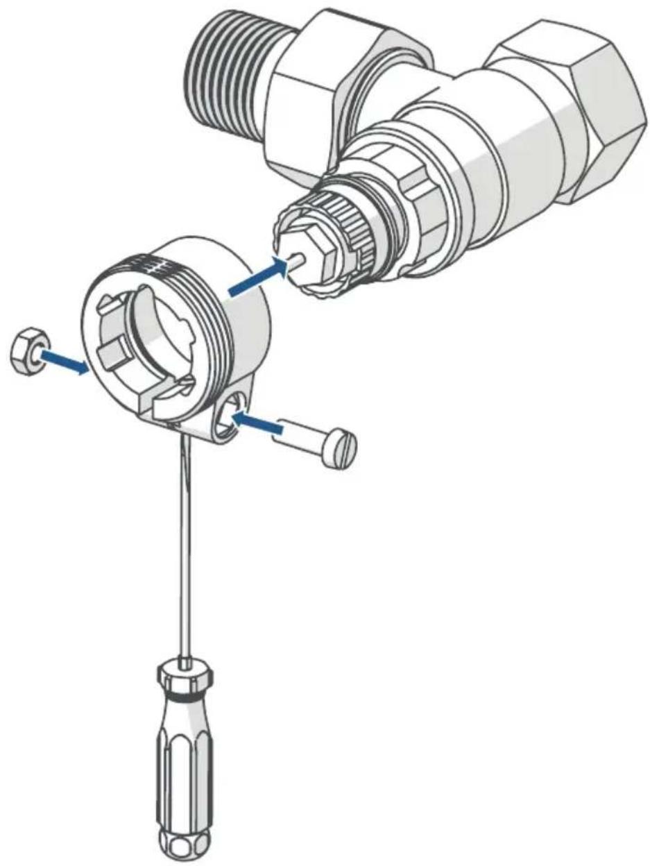
5.2.4 Adapter for Danfoss
One of the adapters supplied is required to attach to Danfoss valves. The assignment of the suitable adapter to the relevant valve is shown in the following illustrations.

Please be careful not to trap your fingers between the two halves of the adapter!
The RA and RAV adapters have been manufactured with pre-tension for a better fit. Use a screwdriver during installation if necessary, and bend the adapter open slightly in the vicinity of the screw (see following figures).
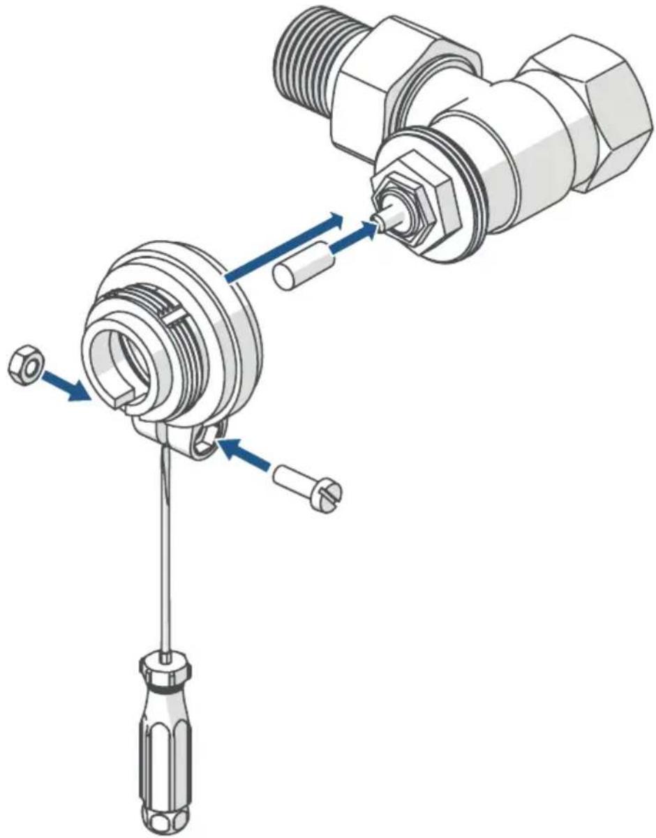
Danfoss RA
Danfoss valve bodies have elongated notches around their circumference, which also ensure that the adapter is properly seated when it snaps on.

During installation, please ensure that the pins inside the adapter are aligned with the notches on the valve.
- Snap the adapter completely onto the valve.
- Secure the adapter with the enclosed screw and nut.
natural_image
Technical illustration of a mechanical assembly with threaded components and screwdriver (no text or symbols)Danfoss RAV
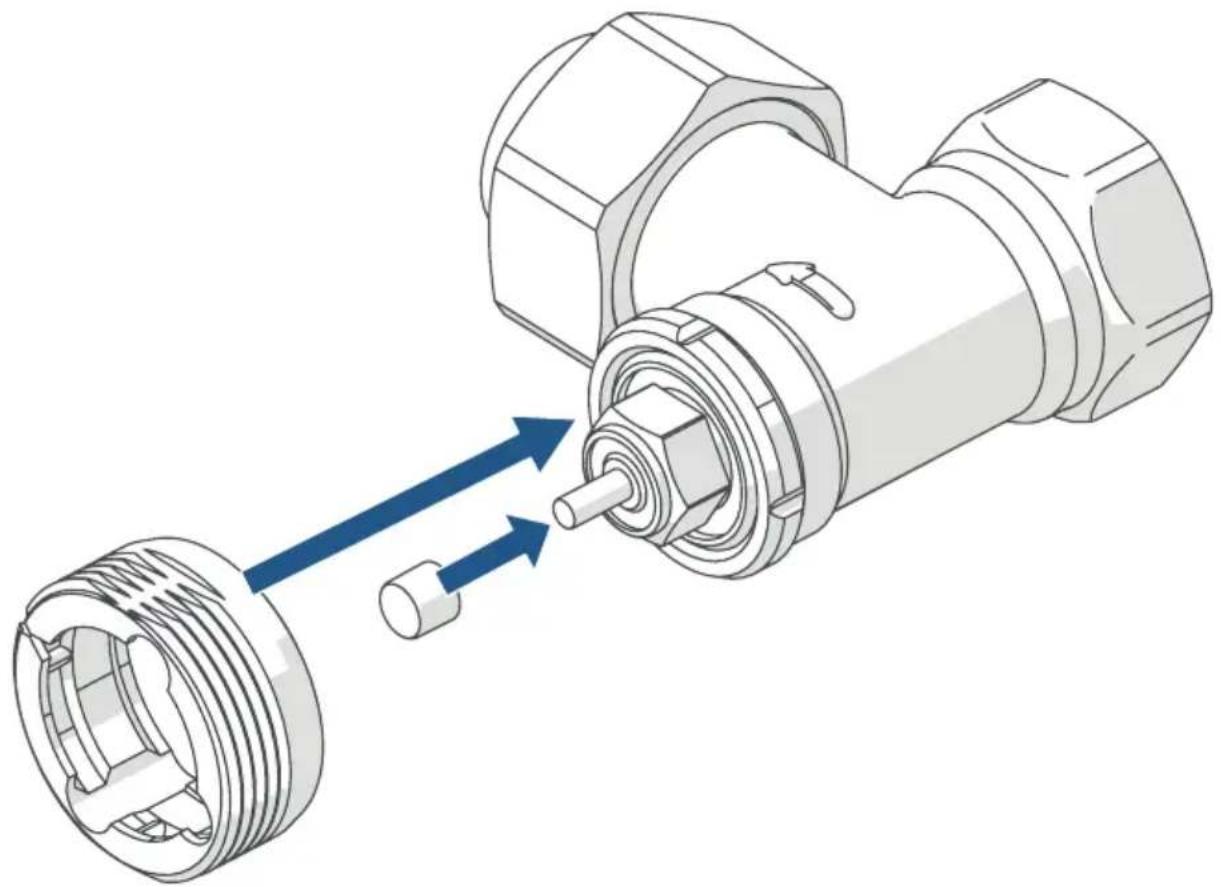
Danfoss valve bodies have elongated notches around their circumference, which also ensure that the adapter is properly seated when it snaps on.

During installation, please ensure that the pins inside the adapter are aligned with the notches on the valve.
- Snap the adapter completely onto the valve.
- Secure the adapter with the enclosed screw and nut.
- Place the spigot extension on the valve pin.
natural_image
Mechanical assembly diagram showing a screwdriver inserted into a mechanical component with blue arrows indicating motion direction (no text or symbols present)Danfoss RAVL
Danfoss valve bodies have elongated notches around their circumference, which also ensure that the adapter is properly seated when it snaps on.

During installation, please ensure that the pins inside the adapter are aligned with the notches on the valve.
- Snap the adapter completely onto the valve.
- Place the spigot extension on the valve pin.

The RAVL adapter does not need to be screwed on.
natural_image
Technical illustration of a mechanical assembly with two components and directional arrows indicating movement (no text or symbols)5.3 Adjustment run

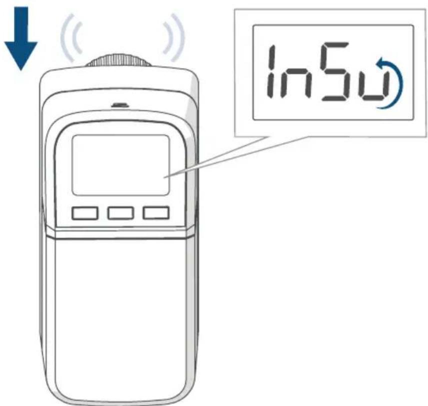
When the batteries are inserted, the motor first reverses to facilitate fitting. While this is happening, "In5" and the activity symbol (u) are displayed (see figure 10).

If the adjustment run was initiated prior to mounting, or if an error message (F1, F2, F3) is displayed, press the system button (D): the motor will reverse to the "In5" position. The adjustment run can then be restarted.
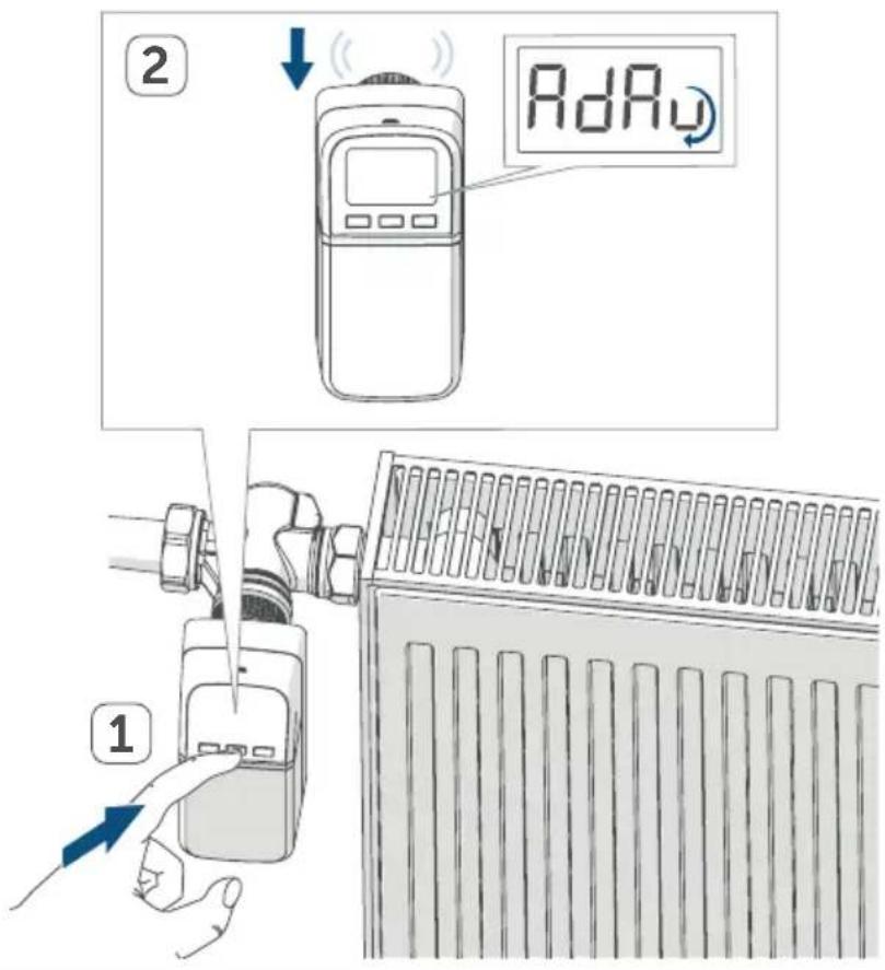
After the radiator thermostat has been mounted successfully, an adjustment run ( R_dR ) must be performed in order to adjust the device to the valve. To do this, proceed as follows:
- As soon as " _RdR " is displayed, press the system button (D), to start the adjustment run (see figure 11).
The radiator thermostat performs the adjustment run, and "RdR" and the activity symbol (u) are displayed. During this time, no other operation is possible. After the adjustment run has been successful, the display returns to normal. The radiator thermostat can now be operated.
6 Configuration menu
If you operate the device without a Homematic IP Access Point, after commissioning you can use the configuration menu to directly select the following modes and adjust the settings to adapt the device to your personal needs:
- Press and hold the menu button (D) to enter the configuration menu.
- Select the desired symbol using the plus and minus buttons (C + E) and briefly press the menu key to adjust settings for the various menu items.

Press and hold the menu button to return to the previous level.
The menu automatically closes without applying changes if there is no operation for more than 1 minute.
| 6.1 | AUTO | Automatic mode |
| 6.2 | MANU | Manual operation |
| 6.3 | Offset | Offset temperature |
| 6.4 | Prg | Programming a heating schedule |
| 6.5 |  | Date and time |
| 6.6 | [BYTK] | Operation lock/PIN entry |
| 6.7 |  | Holiday mode |
| 6.8 | [93DG] | Direct pairing |
| 6.9 | [408Z] | Pairing with the access point |
| 6:10 | [YYXT] | Restoring factory settings |
| 6:11 | [2TTZ] | Changing the PIN |

If you pair the device with the Homematic IP Access Point, you can easily adjust the settings via the free Homematic IP app. After pairing with the access point, the configuration menu on the device can no longer be used.

If you have already adjusted the settings in the configuration menu, or if you have already paired the device with another Homematic IP device, you first have to restore the factory settings of the device before you can pair it with a Homematic IP Access Point or a CCU3 (see see "10 Restoring factory settings" on page 65).
6.1 Automatic operation
In automatic mode, the temperature is controlled in accordance with the set heating schedule. Manual changes are activated until the next point at which the profile changes. Afterwards, the defined heating schedule will be activated again. To activate the automatic mode, please proceed as follows:
- Press and hold the menu button (D) for approx. 2 seconds to open the configuration menu.
- Select "AUTO" using the plus and minus buttons (C + E).
- Confirm with the menu button.
To confirm, the symbol flashes twice and the device changes back to automatic mode.
6.2 Manual operation
In manual mode, the temperature is controlled according to the temperature set using the plus and minus buttons (C + E) . The temperature remains activated until the next manual change. To activate the manual mode, proceed as follows:
- Press and hold the menu button (D) for approx. 2 seconds to open the configuration menu.
- Select "MANU" using the plus and minus buttons (C + E).
- Confirm with the menu button.
To confirm, the symbol flashes twice and the device changes back to manual mode.
6.3 Offset temperature
As the temperature is measured on the radiator thermostat, the temperature distribution can vary throughout a room. To adjust for this, a temperature offset of ±3.5 ^ can be set. If, for example, 18 ^ is measured instead of the 20 ^ set, an offset of -2.0 ^ must be set. An offset temperature of 0.0 ^ is set in the factory settings. To adjust the offset temperature, please proceed as follows:
- Press and hold the menu button (D) for approx. 2 seconds to open the configuration menu.
- Select "OFFSET" using the plus and minus buttons (C + E).
- Confirm with the menu button.
- Select the desired offset temperature using the plus and minus buttons and confirm with the menu button.
To confirm, the temperature flashes twice and the device changes back to the standard display.
6.4 Programming a heating schedule
In this menu item, you can create a heating schedule with heating and cooling phases according to your personal needs.
- Press and hold the menu button (D) for approx. 2 seconds to open the configuration menu.
- Select "PRG" using the plus and minus buttons (C + E) and confirm with the menu button.
- Under the menu item "DAY", use the plus and minus buttons to select individual weekdays, all weekdays, the weekend or the entire week for your heating schedule and confirm with the menu button.
- Confirm the start time 00:00 hours with the menu button.
- Select the desired temperature and start time using the plus and minus buttons and confirm with the menu button.
- The next time is shown in the display. You can adjust this time using the plus and minus buttons.
- Select the desired temperature for the next time period using the plus and minus buttons and confirm with the menu button.
- Repeat this procedure until temperatures are stored for the entire period between 0:00 and 23:59 h.
To confirm, the time flashes twice, and the device changes back to the standard display.
6.5 Time and date
To set the date and time, please proceed as follows:
- Press and hold the menu button (D) for approx. 2 seconds to open the configuration menu.
- Select "DATE/TIME" using the plus and minus buttons (C + E).
- Confirm with the menu button.
- Select the desired year using the plus and minus buttons and confirm with the menu button.
-
Select the desired month using the plus and minus buttons and confirm with the menu button.
-
Select the desired day using the plus and minus buttons and confirm with the menu button.
- Select the desired hours using the plus and minus buttons and confirm with the menu button.
- Select the desired minutes using the plus and minus buttons and confirm with the menu button.
To confirm, the time flashes twice, and the device changes back to the standard display.
6.6 Operation lock/PIN entry
Operation of the device can be locked with a personal PIN to prevent unintentional changes to the setpoint temperature or the settings. To activate the operation lock, proceed as follows:
- Press and hold the menu button (D) for approx. 2 seconds to open the configuration menu.
- Select "Operation lock" ( 🔊) using the plus and minus buttons (C + E).
- Confirm with the menu button.
Activating the operation lock
- To activate the operation lock and enter the PIN, select "On" using the plus button (C) "On" and confirm with the menu button.
- "PIN" appears in the display. Confirm with the menu button.
- "0000" appears in the display. Select the first desired digit of the PIN using the plus and minus buttons and confirm with the menu button to switch to the next digit.
- Now enter the second, third and fourth digits of the PIN in the same way and confirm each entry with the menu button.
"SAFE" appears in the display. The operation lock is now active. After the operation lock has been activated, the symbol "💡" is displayed.
Deactivating the operation lock
- To deactivate the operation lock again, press the menu key until the menu for the operation lock (💡) is displayed. Confirm with the menu button.
- Select "OFF" using the minus button (E) and confirm with the menu button.
- "PIN" appears in the display. Confirm with the menu button to enter the PIN.
- Enter the four digits of your PIN using the plus and minus buttons and confirm with the menu button.
"SAFE" appears in the display. The operation lock is now no longer active. The device switches back to the standard display.
6.7 Holiday mode
If you want to maintain a constant temperature for a certain period, e.g. during your holidays or a party, the holiday mode can be used. To activate the holiday mode, please proceed as follows:
- Press and hold the menu button (D) for approx. 2 seconds to open the configuration menu.
- Select "Holiday" using the plus and minus buttons (C + E) and confirm with the menu button.
- Use the plus and minus buttons to select the time until which you want to activate the holiday mode and confirm with the menu button.
- Use the plus and minus buttons to select the date, until which you want to activate the holiday mode and confirm with the menu button.
- Use the plus and minus buttons to select the temperature for the holiday mode and confirm with the menu button.
To confirm, the symbol flashes twice and the device changes to holiday mode.
6.8 Direct pairing
To pair the radiator thermostat directly with another Homematic IP device, you can activate the pairing mode for direct pairing as follows:
- Press and hold the menu button (D) for approx. 2 seconds to open the configuration menu.
- Select "PAIR" using the plus and minus buttons (C + E) and confirm with the menu button.
- Fast orange flashing indicates the pairing mode is activated.
6.9 Pairing with the access point
To pair the radiator thermostat with a Homematic IP Access Point, you can activate the pairing mode as follows:
- Press and hold the menu button (D) for approx. 2 seconds to open the configuration menu.
- Select "INCL" using the plus and minus buttons (C + E) and confirm with the menu button.
- The menu item flashes to indicate that the pairing mode is activated.
6.10 Restoring factory settings

The device's factory settings can be restored. If you do this, you will lose all your settings.
To restore the factory settings of the device, please proceed as follows:
- Press and hold the menu button (D) for approx. 2 seconds to open the configuration menu.
- Select "RES" using the plus and minus buttons (C + E) and confirm with the menu button.
- Press and hold the menu button until the device LED (D) starts to quickly flash orange.
- Briefly release the menu button then press and hold the menu button again until the orange flashing changes to a steady green light.
- Release the menu button again to finish restoring the factory settings. The device will perform a restart.
6.11 Changing the PIN
To change the assigned PIN, proceed as follows:
- Press and hold the menu button (D) for approx. 2 seconds to open the configuration menu.
- Select "PIN" using the plus and minus buttons (C + E).
- Confirm with the menu button.
- "OLD" appears in the display. Confirm with the menu button to change the existing PIN. The factory setting for the PIN is "0000".
- "0000" appears in the display. Enter the first digit of the existing PIN using the plus and minus buttons and confirm with the menu button to switch to the next digit.
- Now enter the second, third and fourth digits of the PIN in the same way and confirm each entry with the menu button.
- "NEW" appears in the display. Confirm with the menu button to enter the new PIN.
- "0000" appears in the display. One after another, enter the digits of the new PIN using the plus and minus buttons and confirm with the menu button.
"SAFE" appears in the display. The new PIN has been saved. The device switches back to the standard display.
7 Operation

If the radiator thermostat is in standby mode (display lighting off), you must press a button (C, D or E) on the radiator thermostat before operation in order to activate it (display lighting on).
After pairing and mounting have been performed, simple operations are available directly on the device.
- Temperature: Press the plus (C) or minus button (E) to manually change the radiator temperature. In automatic mode, the manually set temperature will remain the same until the next point at which the schedule changes. Afterwards, the defined heating schedule will be activated again. During manual operation, the temperature remains activated until the next manual change.
- Boost function: Briefly press the boost button (D) to activate the boost function and heat up the radiator quickly and temporarily by opening the valve. There will be a pleasant room temperature right away because of the radiated heat.
8 Changing the batteries
If the symbol for empty batteries (☐) appears in the display or in the app, please replace the used batteries with four new LR6/Mignon/AA batteries. You must observe the correct battery polarity.
To insert new batteries, proceed as follows:
- Open the battery compartments by pulling the cover (F) first downwards and then forwards (see figure 3).
- Remove the used batteries.
- Insert four new 1.5 V LR6/mignon/AA batteries into the battery compartment, making sure they are the right way round (see figure 12).
- Close the battery compartment.
- Please pay attention to the flashing signals of the device LED while inserting the batteries (see see „9.4 Error codes and flashing sequences“ on page 63).
Once the batteries have been inserted, the radiator thermostat will perform a self-test and an adjustment run, if required (approx. 2 seconds). Afterwards, initialisation is carried out. The LED test display will indicate that initialisation is complete by lighting up orange and green.

Caution! There is a risk of explosion if the batteries are not replaced correctly. Replace only with the same or equivalent type. Never recharge non-rechargeable batteries. Do not throw the batteries into a fire. Do not expose batteries to excessive heat. Do not short-circuit batteries. Doing so will present a risk of explosion.

Caution! Avoid skin and eye contact when handling leaking batteries. Wear suitable protective gloves when removing leaking batteries and residues from a device. Rinse with plenty of water in the event of skin contact.

If the radiator thermostat is not used for a longer period of time, e.g. during storage, remove the batteries to avoid damage caused by the batteries leaking.

Used batteries should not be disposed of with regular domestic waste! Instead, take them to your local battery disposal point.
9 Troubleshooting
9.1 Weak batteries
Provided that the voltage value permits it, the radiator thermostat will remain ready for operation even if the battery voltage is low. Depending on the particular load, it may be possible to send transmissions again repeatedly once the batteries have been allowed a brief recovery period. If the voltage drops too far during transmission, the empty battery symbol (☐) and the corresponding error code will be displayed on the device (see see „9.4 Error codes and flashing sequences“ on page 63). In this case, replace the empty batteries with four new batteries (see see „8 Changing the batteries“ on page 61).
9.2 Command not confirmed
If at least one receiver does not confirm a command, the device LED (D) lights up red at the end of the failed transmission process. The failed transmission may be caused by radio interference (see see „12 General information about radio operation“ on page 66). This may be caused by the following:
- Receiver cannot be reached.
- Receiver is unable to execute the command (load failure, mechanical blockade, etc.).
- Receiver is faulty.
9.3 Duty cycle
The duty cycle is a legally regulated limit of the transmission time of devices in the 868 MHz range. The aim of this regulation is to safeguard the operation of all devices working in the 868 MHz range.
In the 868 MHz frequency range we use, the maximum transmission time of any device is 1% of an hour (i.e. 36 seconds in an hour). Devices must cease transmission when they reach the 1% limit until this time restriction ends. Homematic IP devices are designed and produced with 100% conformity to this regulation.
During normal operation, the duty cycle is not usually reached. However, repeated and radio-intensive pairing processes mean that it may be reached in isolated instances during start-up or initial installation of a system. If the duty cycle is exceeded, this is indicated by one long flash of the device LED (D), and it may have the effect of the device temporarily working incorrectly. The device will start working correctly again after a short period (max. 1 hour).
9.4 Error codes and flashing sequences
| Flashing code/ display | Meaning Solution | |
| F1 Valve drive sluggish | Please check whether the valve pin is stuck. | |
| F2 | Actuating range too wide | Check the radiator thermo-stat is mounted securely |
| F3 | Adjustment range too small | Please check whether the valve pin is stuck. |
| Battery symbol (☐) | Battery voltage low | Replace the batteries of the device (see see „8 Chang-ing the batteries“ on page 61). |
| Battery symbol (☐) and --- | Valve moved to error position* | Replace the batteries of the device (see see „8 Chang-ing the batteries“ on page 61). |
| *If empty batteries are not replaced, the radiator thermostat moves to a "valve error position". This avoids, a situation where the set temperature in the room cannot be reached any more due to a low battery. A valve error position of 15 % is set in the factory settings. | ||
| Antenna symbol (☒) flashing | Communication problem with Homematic IP Access Point or connected device | Please check the connec-tion with the Homematic IP Access Point or the con- nected devices. |
| Lock symbol (☐) | Operating lock acti-vated | Deactivate the operation lock on the device or in the app. |
| Brief orange flashing | Radio transmission/attempting to trans-mit/configuration data is transmitted | Wait until the transmission is completed. |
| 1x long green flash | Transmission con-firmed | You can continue operation. |
| 1x long red flash | Transmission failed or duty cycle limit reached | Please try again (see sec. see „9.2 Command not con-firmed“ on page 62 or see „9.3 Duty cycle“ on page 63). |
| Brief orange flashing (every 10 s) | Pairing mode active | Enter the last four numbers of the device's serial number to confirm (see “5.1.2 Pairing with the access point” auf Seite 46). |
| Fast orange flashing | Direct pairing mode active | Activate the pairing mode of the device you want to add (see see „5.1.1 Direct pairing with a Homematic IP device" on page 45). |
| Brief steady or-ange light (after green or red confirmation) | Batteries empty | Replace the batteries (see see „8 Changing the batter-ies" on page 61). |
| 6x long red flashes | Device defective | Please see your app for error message or contact your retailer. |
| 1x orange and 1x green light (after inserting batteries) | Test display | You can continue once the test display has stopped. |
| Alternating long and short orange flashing | Device software up-dating (OTAU) | Wait until the update is completed. |
10 Restoring factory settings

The device's factory settings can be restored. If you do this, you will lose all your settings.
To restore the factory settings of the device, please proceed as follows:
- Open the battery compartments by pulling the cover (F) first downwards and then forwards (see figure 3).
-
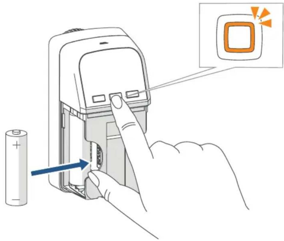
Remove one battery.
-
Re-insert the battery, making sure that it is right way around, while simultaneously pressing and holding the menu button (D). Hold down the menu button until the LED (D) starts to quickly flash orange (see figure 13).
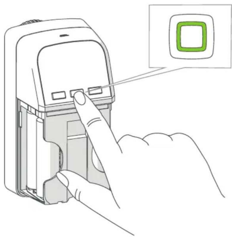
- Briefly release the menu button then press and hold the menu button again until the orange flashing changes to a steady green light (see figure 14).
- Release the menu button again to finish restoring the factory settings.
The device will perform a restart.
11 Maintenance and cleaning

The device does not require you to carry out any maintenance other than replacing the battery when necessary. Enlist the help of an expert to carry out any repairs.
Clean the device using a soft, lint-free cloth that is clean and dry. Do not use any detergents containing solvents, as they could corrode the plastic housing and label.
12 General information about radio operation
Radio transmission is performed on a non-exclusive transmission path, which means that there is a possibility of interference occurring. Interference can also be caused by switching operations, electrical motors or defective electrical devices.

The transmission range within buildings can differ significantly from that available in the open air. Besides the transmitting power and the reception characteristics of the receiver, environmental factors such as humidity in the vicinity play an important role, as do on-site structural/screening conditions.
eQ-3 AG, Maiburger Straße 29, 26789 Leer, Germany hereby declares that the radio equipment type Homematic IP HmIP-eTRV-CL is compliant with Directive 2014/53/EU. The full text of the EU declaration of conformity is available at www.homematic-ip.com
13 Technical specifications
Device short description: HmIP-eTRV-CL
Supply voltage: 4x 1.5 V LR6/Mignon/AA
Current consumption: 100 mA max.
Battery life: 7 years (typical)
Protection rating: IP20
Pollution degree: 2
Ambient temperature: 0 to 50 °C
Dimensions (W x H x D): 54 x 108 x 65 mm
Weight: 260 g (including batteries)
Radio frequency band: 868.0-868.6 MHz 869.4-869.65 MHz
Max. radio transmission power: 10 dBm
Receiver category: SRD category 2
Typical range in open space: 280 m
Duty cycle: < 1 % per h/< 10 % per h
Software class: Class A
Method of operation: Type 1
Connection: M30 x 1.5 mm
Controlling torque: > 80 N
Valve travel: 4.3 ± 0.3 mm
Maximum travel position: 14.3 ± 0.3 mm
Minimum travel position: 10.0 ± 0.3 mm
Subject to modifications.
Instructions for disposal
Do not dispose of the device with normal domestic waste! Electronic equipment must be disposed of at local collection points for waste electronic equipment in compliance with the Waste Electrical and Electronic Equipment Directive. Before disposing of the unit, remove any batteries that have been inserted.
Information about conformity

The CE mark is a free trademark that is intended exclusively for the authorities and does not imply any assurance of properties.

For technical support, please contact your retailer.
5.2.3 Bague de support
natural_image
Technical illustration of a mechanical assembly with threaded components and screwdriver (no text or symbols)Danfoss RAV
natural_image
Mechanical assembly diagram showing a screwdriver inserted into a threaded component via a tool, with no visible text or symbols.Danfoss RAVL
natural_image
Technical illustration of a mechanical assembly showing two components with directional arrows indicating movement or force (no text or symbols present)Poids : 260 g (piles comprises)
Printed in Hong Kong
natural_image
Technical illustration of a mechanical assembly with threaded components and screwdriver (no text or symbols)Danfoss RAV
natural_image
Mechanical assembly diagram showing a screwdriver inserted into a threaded component via a tool, with no visible text or symbols.Danfoss RAVL
natural_image
Technical illustration of a mechanical assembly with two components and directional arrows indicating motion (no text or symbols)natural_image
Technical illustration of a mechanical assembly with threaded components and screwdriver (no text or symbols)Danfoss RAV
natural_image
Mechanical assembly diagram showing a screwdriver inserted into a threaded component via a tool, with no visible text or symbols.Danfoss RAVL
natural_image
Technical illustration of a mechanical assembly with two components and directional arrows indicating movement (no text or symbols)Printed in Hong Kong
natural_image
Technical illustration of a mechanical assembly with threaded components and screwdriver (no text or symbols)Danfoss RAV
natural_image
Mechanical assembly diagram showing a threaded fastener and screwdriver with blue directional arrows indicating motion (no text or labels)Danfoss RAVL
natural_image
Technical illustration of a mechanical assembly showing two components with directional arrows indicating movement or force (no text or symbols present)Apparaatcode: HmIP-eTRV-CL
Voedingsspanning: 4x 1,5 V LR6/mignon/AA
Stroomopname: 100 mA max.
Free download of the Homematic IP app!

text_image
Blue QR code image, scannable for digital information retrieval
Download on the
App Store

text_image
Blue QR code image containing encoded data, no visible text or symbols beyond the matrix pattern
ANDROID APP ON
Google play
Bevollmächtigter des Herstellers: Manufacturer's authorised representative:

eQ-3 AG
Maiburger Straße 29
26789 Leer / GERMANY
www.eQ-3.de