Pro Line SLC 330 - Food slicer Berkel - Free user manual and instructions
Find the device manual for free Pro Line SLC 330 Berkel in PDF.

User questions about Pro Line SLC 330 Berkel
0 question about this device. Answer the ones you know or ask your own.
Ask a new question about this device
Download the instructions for your Food slicer in PDF format for free! Find your manual Pro Line SLC 330 - Berkel and take your electronic device back in hand. On this page are published all the documents necessary for the use of your device. Pro Line SLC 330 by Berkel.
USER MANUAL Pro Line SLC 330 Berkel
ELEVATING YOUR PASSION, SINCE 1898.
PRO LINE SERIES
PRO LINE VS25 - VS30
PRO LINE GL30
PRO LINE GL30 AUTO
PRO LINE SLC 300 - 330 - 350
PRO LINE SLC 350A
EN USER MANUAL
IT MANUALE D'USO
FR MANUEL D'INSTRUCTIONS
CS NÁVOD K POUŽITÍ
DA BETJENINGSVEJLEDNING
natural_image
Technical line drawing of a mechanical device with circular components and a rotating shaft (no text or symbols)(Q)
natural_image
Diagram showing a device with a close-up inset of its internal components (no text or symbols visible)(B)
natural_image
Technical line drawing of a mechanical device with no visible text or symbols(C)
natural_image
Illustration of two types of industrial cutting machines with rotating blades and a handle (no text or symbols)(D)
natural_image
Technical line drawing of a mechanical assembly (no text or symbols)(G)
natural_image
Illustration of a hand operating a rotary pump with warning symbol (no text or labels)(L) (M) (N)
natural_image
Line drawing of a hand holding a device with a tool, no text or symbols present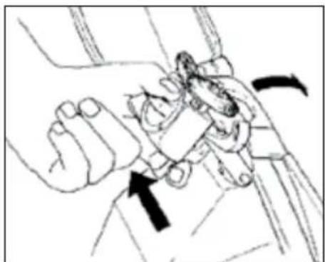
natural_image
Illustration of a hand holding a small object with directional arrows indicating movement (no text or symbols)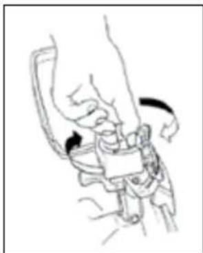
natural_image
Line drawing of a mechanical device with a handle and lever mechanism (no text or symbols)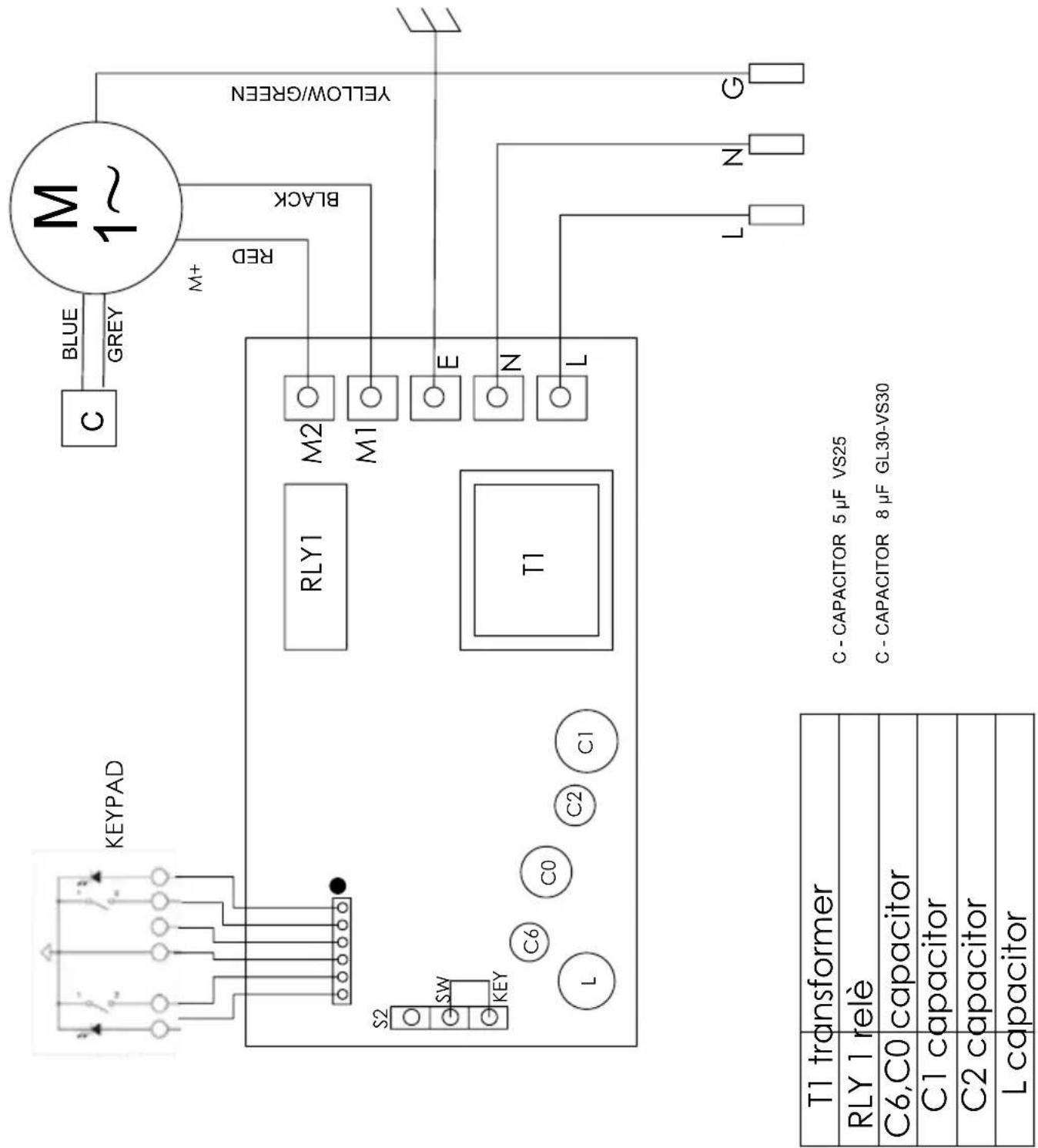
PRO LINE VS25-VS30
PRO LINE GL30
Fig. 1 - Abb. 1 - Obr. 1 - Afb. 1 - Bild 1
flowchart
graph TD
    A["MONO PHASE MOTOR 1 KW U-V"] --> B["K1"]
    C["MONO PHASE POWER SUPPLY L1-L2"] --> B
    B --> D["X1"]
    B --> E["X1"]
    B --> F["T1"]
    D --> G["ANDER"]
    E --> H["ANDER"]
    F --> I["ANDER"]
    G --> J["ANTITAMPER CONTROL PANEL"]
    H --> J
    I --> J
    J --> K["LED START"]
    J --> L["START N.O."]
    J --> M["STOP N.C."]
    J --> N["LED STOP"]
    K --> O["BROWN"]
    K --> P["BROWN WHITE"]
    K --> Q["GREEN YELLOW"]
    K --> R["YELLOW GREEN"]
    K --> S["BLUE"]
    K --> T["WHITE"]
    L --> U["INTUITAMPER CONTROL Panel"]
    M --> U
    N --> U
    O --> V["SELF RESTORE FUSE"]
    P --> V
    Q --> V
    R --> V
    S --> V
    T --> V
    U --> W["14 µF"]
    V --> X["14 µF"]
    Y["GREY BLACK"] --> Z["M1"]
    AA["WHITE or RED"] --> Z
    AB["BLUE"] --> Z
    AC["L2"] --> AD["L1"]
    AE["L1"] --> AF["L2"]
    AG["G"] --> AH["GND"]
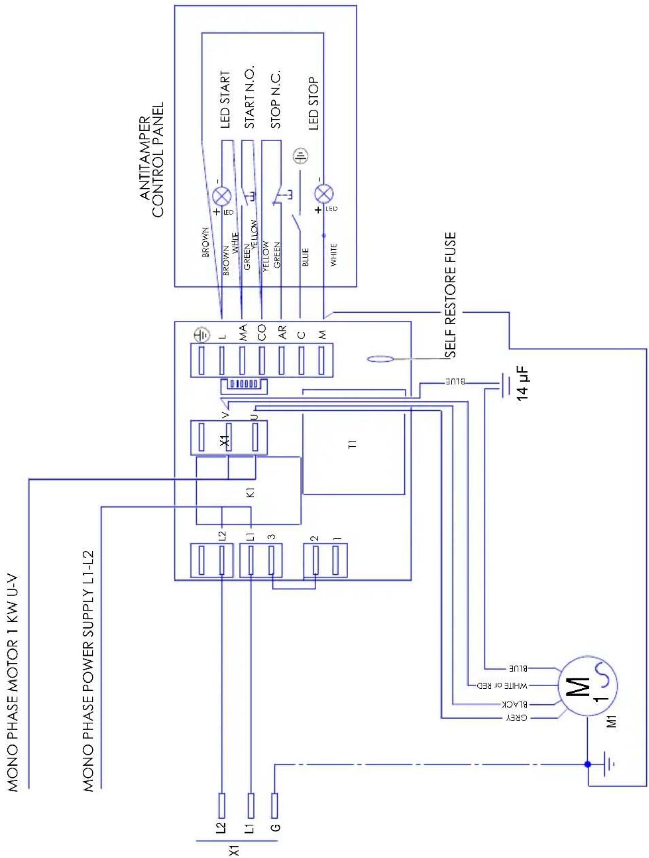
PRO LINE SLC300-330-350
Fig. 1 - Abb. 1 - Obr. 1 - Afb. 1 - Bild 1
flowchart
graph TD
    A["THREE PHASE MOTOR 1 KW U-V-W"] --> B["X1"]
    C["THREE PHASE POWER SUPPLY L1-L2-L3"] --> D["K1"]
    E["ANTITAMPER CONTROL PANEL"] --> F["T1"]
    G["SELF RESTORE FUSE"] --> H["M1"]
    I["Black"] --> J["BLACK"]
    K["White OR RED OR BROWN"] --> L["BLUE"]
    M["Blue"] --> N["Black"]
    O["WHITE"] --> P["WHITE"]
    Q["Brown"] --> R["LED START"]
    S["Brown"] --> T["LED STOP"]
    U["GREEN YELLOW"] --> V["STOP N.O."]
    W["YELLOW GREEN"] --> X["STOP N.C."]
    Y["WHITE"] --> Z["LED STOP"]
    AA["+/-"] --> AB["+/-"]
    AC["IMP. ELE. 14 400V/50 Hz"] --> AD["Power Supply"]
    AE["X1"] --> AF["L3"]
    AF --> AG["L2"]
    AG --> AH["L1"]
    AH --> AI["G"]
    AJ["X1"] --> AK["L3"]
    AK --> AL["L2"]
    AL --> AM["L1"]
    AM --> AN["G"]
    AO["T1"] --> AP["X1"]
    AP --> AQ["W"]
    AP --> AR["V"]
    AP --> AS["U"]
    AT["Black"] --> AU["BLACK"]
    AU --> AV["WHITE OR RED OR BROWN"]
    AW["Blue"] --> AX["Blue"]
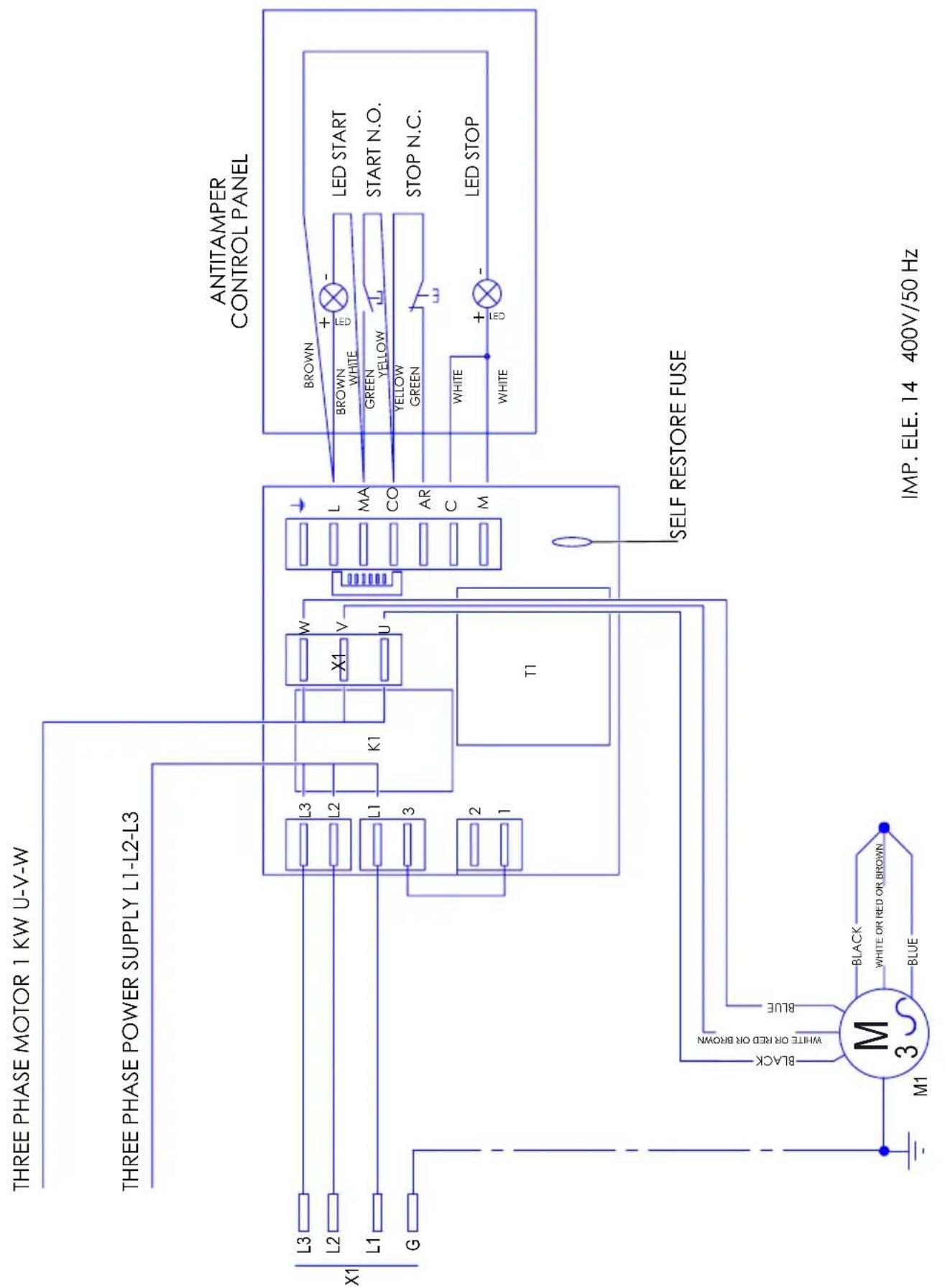
PRO LINE SLC300-330-350
Fig. 1 - Abb. 1 - Obr. 1 - Afb. 1 - Bild 1
Fig. 1 - Abb. 1 - Obr. 1 - Afb. 1 - Bild 1
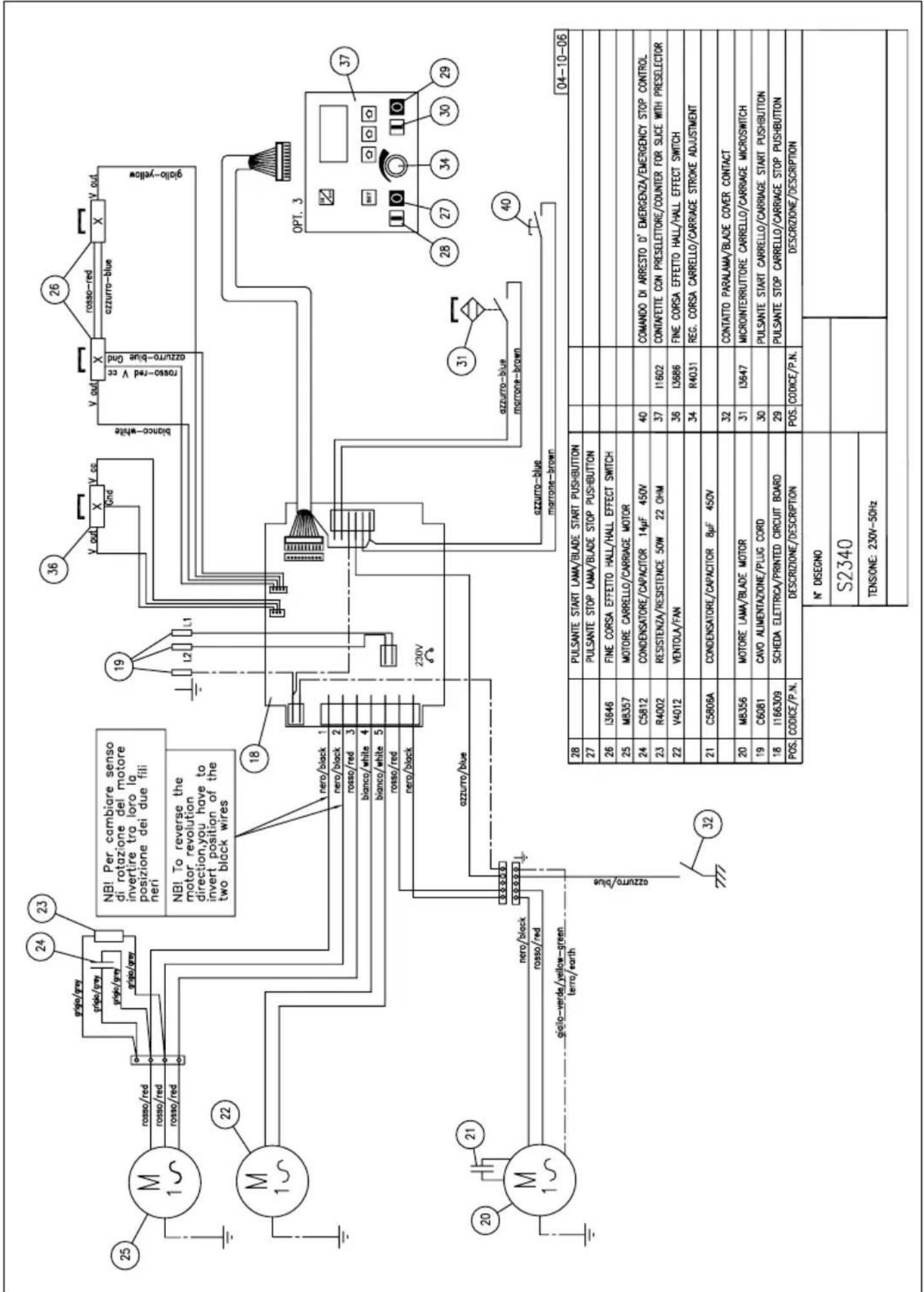
Fig. 1 - Abb. 1 - Obr. 1 - Afb. 1 - Bild 1
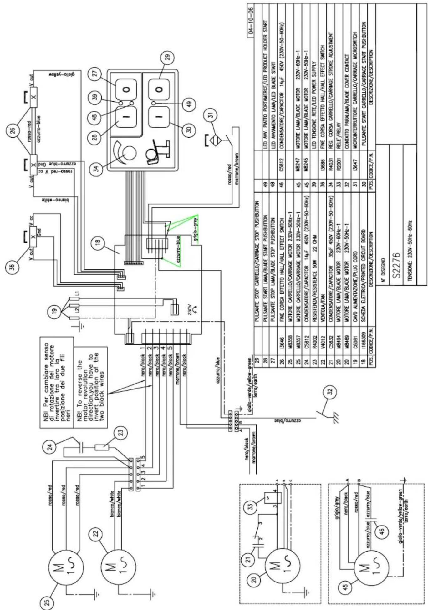
Fig. 1 - Abb. 1 - Obr. 1 - Afb. 1 - Bild 1
PRO LINE SCL350A
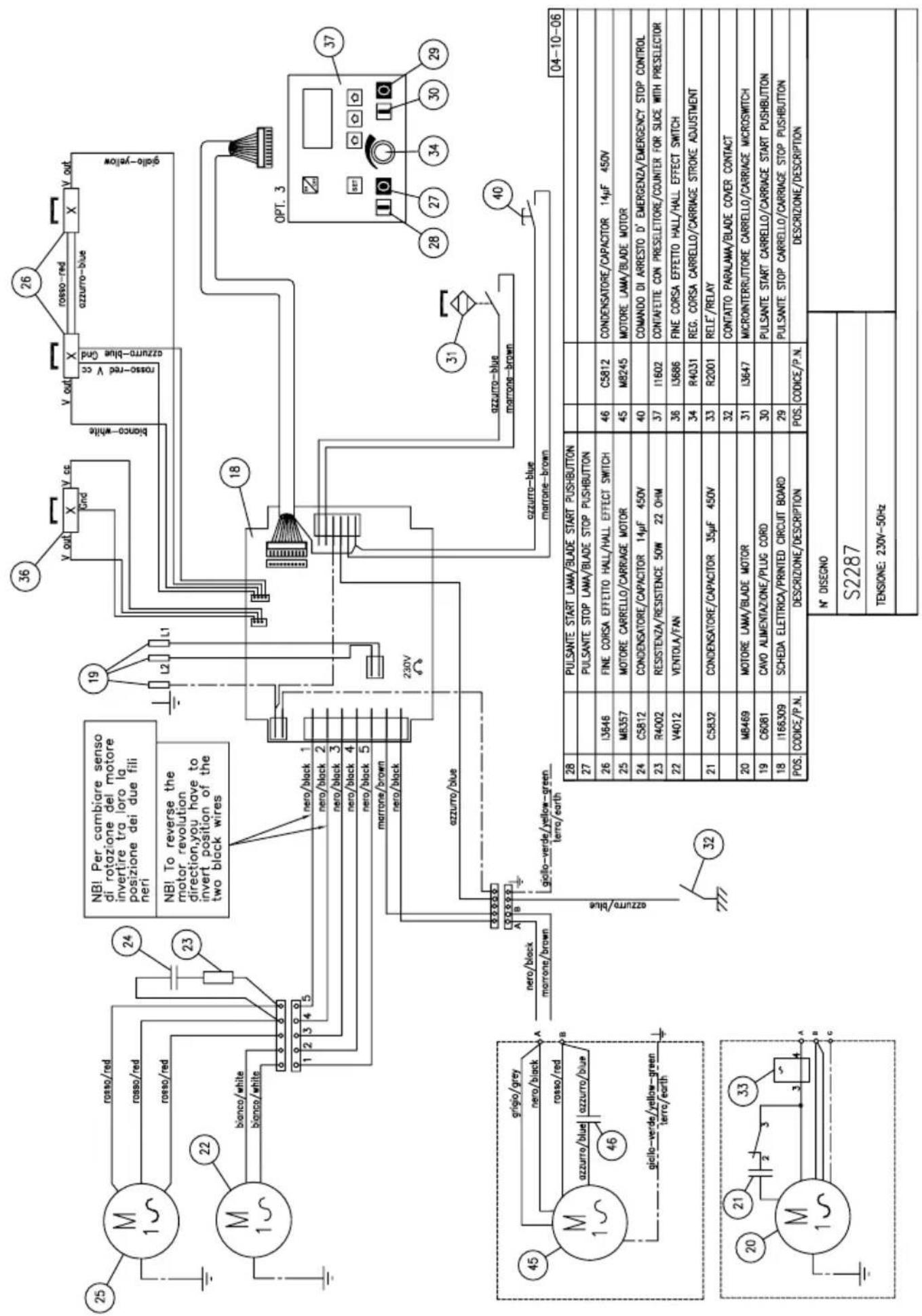
Fig. 1 - Abb. 1 - Obr. 1 - Afb. 1 - Bild 1
PRO LINE SLC350A Optional 3
USER MANUAL: Electrical Slicers Pro Line
MODELS:
GL30, GL30AUTO, VS25, VS30, SLC 300-330-350, SLC 350A


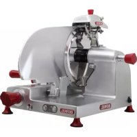
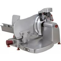
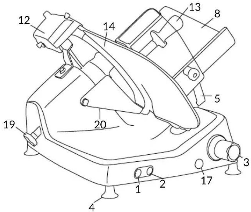
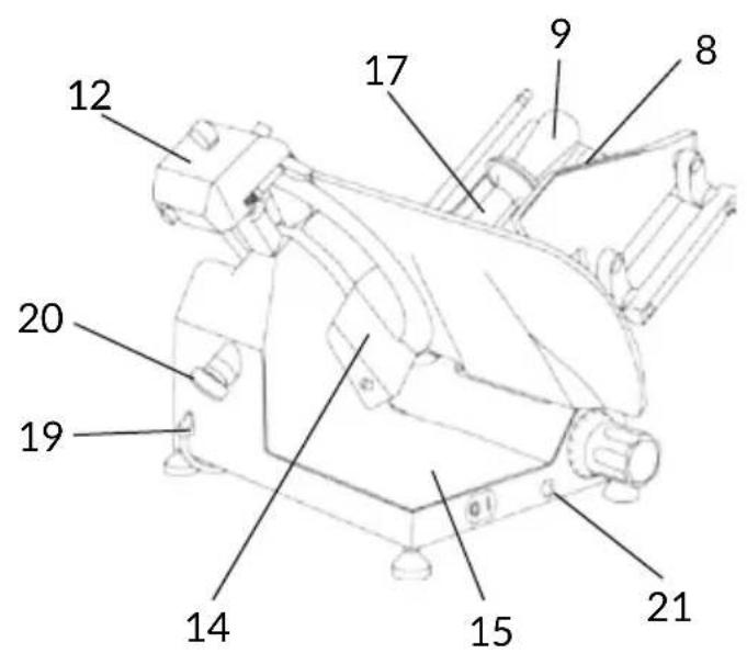
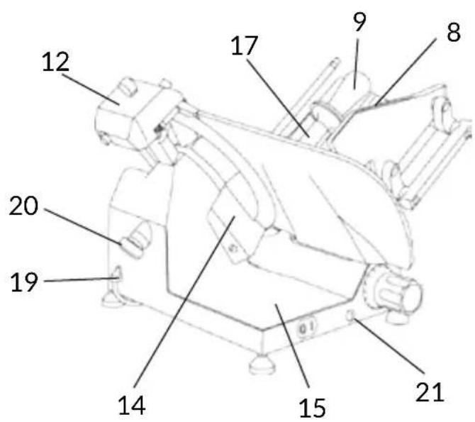
GENERAL PLAN OF THE MACHINE
- Start button
- Stop button
- Plate locking knob
- Foot
- Thickness adjustment knob
- Thickness gauge plate
- Safety guards
- Meat table
- Product press holder
- Blade
- Safety ring (blade guard)
- Sharpener
- Blade cover knob
- Slice guard
- Baseplate
- Carriage
- Product holder
- Blade guard disk
- Power cable
- Blade cover tension rod
- Carriage bar oiler
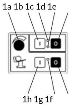
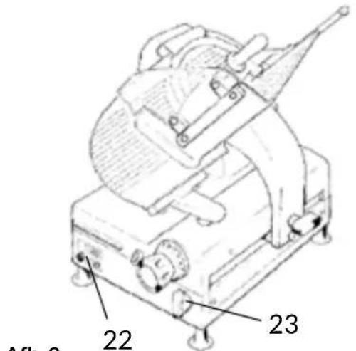
GL30 AUTO
-
Control pushbuttons
-
Carriage release handle
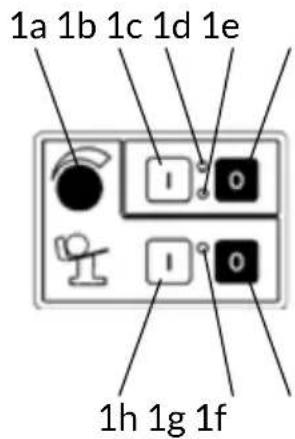
1a. Product holder extension adjustment knob
1b. Start blade
1c. Led - Start blade
1d. Led - Power supply
1e. Stop blade
1f. Stop meat table
1g. Led - Start meat table
1h. Start meat table
Fig. 2

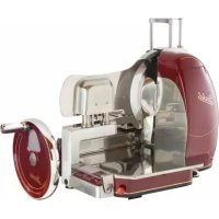
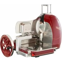
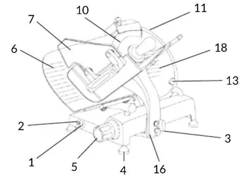
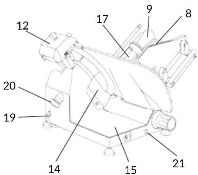
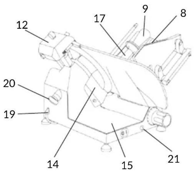
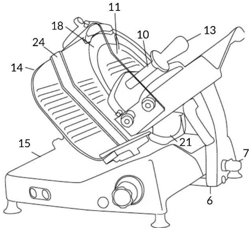
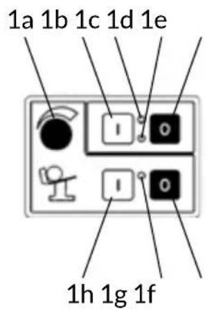
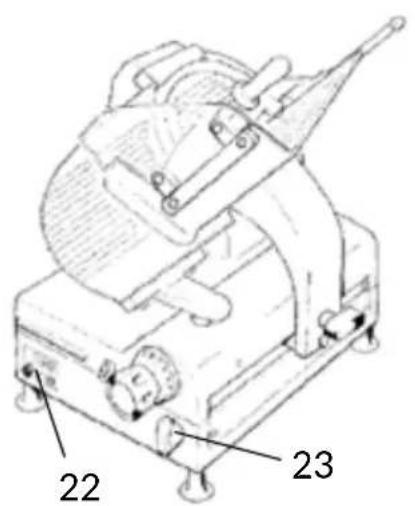
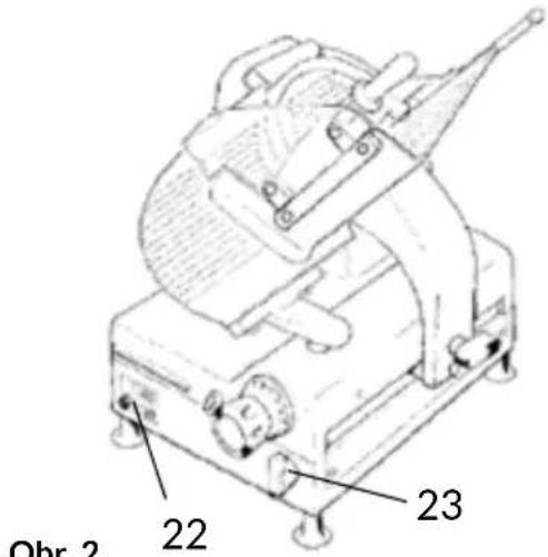
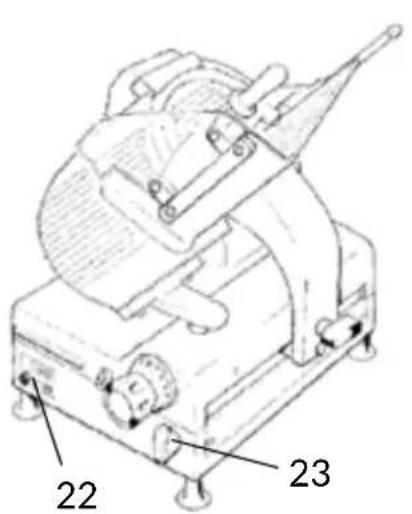
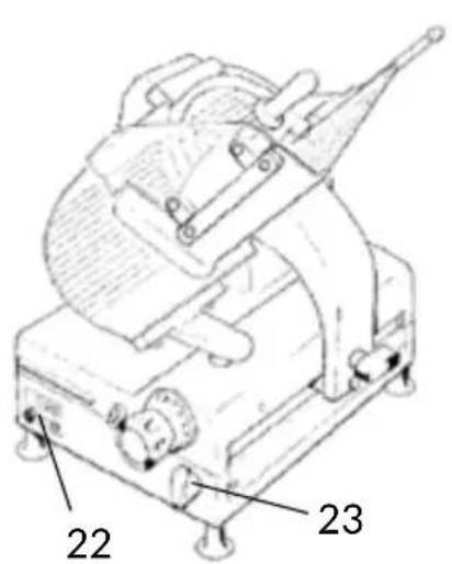
SLC 300 - 330 - 350
SLC 350A
MAIN
COMPONENTS
- Start button
- Stop button
- Slice thickness regulating knob
- Foot
- Handle for plate pushing
- Carriage
- Plate locking knob
- Meat table
- Top clamp
- Blade cover (blade cover)
- Sharpener
- Product holder handle
- Thickness gauge plate
- Casing
- Lubricating point for guide bars
- Blade
- Blade cover tension rod
- Slice deflector
- Blade guard ring
- Meat table safety guard
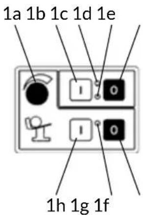
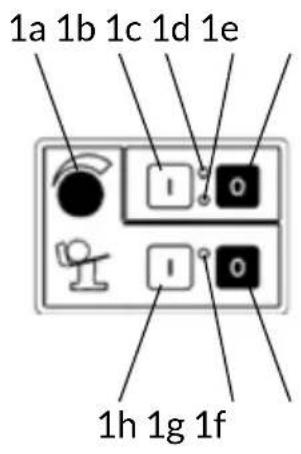
SLC 350A
- Control pushbuttons
- Carriage release handle
1a. Product holder extension adjustment knob
1b. Start blade
1c. Led - Start blade
1d. Led - Power supply
1e. Stop blade
1f. Stop meat table
1g. Led - Start meat table
1h. Start meat table
Fig. 2
DESCRIPTION
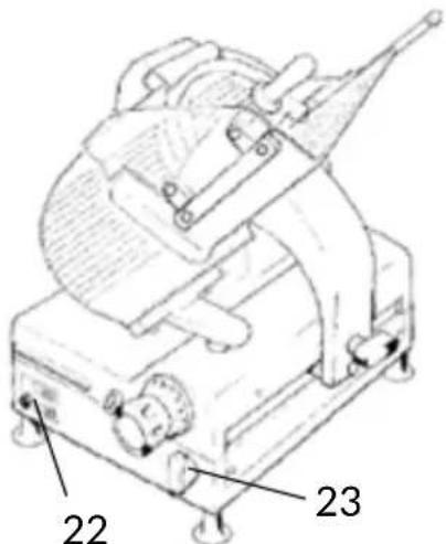
Circular blade professional slicer machine suitable for cutting only the food products of the types and within the dimensional limits indicated in this manual. The main parts of the machine are shown in the general component diagram reported in Fig. 2. Electrical diagrams are reported in Fig. 1.
DECLARATION OF CONFORMITY
The machines described in this manual comply with Directives 2006/42/CE, 2006/95/CE, 2004/108/CE, 2003/108/CE, 2011/65/CE, Regulation (EC) 1935/2004 and related harmonized standards as EN 1974:1998 +A1, EN60204-1, EN60335-1, EN60335-2-64.

SAFETY
Pay attention to the following basic safety precautions:
- read all the instructions before using the machine;
- this product is not intended to be used by children;
- operate the machine only if properly trained and in perfect psycho-physical conditions.
- do not use the machine in any way other than what indicated in this manual;
- use the machines only in full structural, mechanical and system efficiency;
- install the machine in conformity to the instructions indicated in the "Installation" section;
- install the machine in a location out of the reach of personnel unauthorized to operate it
and especially out of the reach of minors;
- stay highly concentrated when using the machine and avoid any distraction during use;
- do not allow the machine to be used by others who have not read and fully understood the content of this manual;
- do not wear baggy clothing or clothing with open sleeves;
- do not allow anyone else, other than the operator, to approach during product cutting operations;
- do not remove, cover or modify the tags located on the machine body and, in case of damage of these, replace them promptly;
- do not remove the transparent guards and do not modify or bypass any mechanical and electrical protective devices;
- slice only the permitted products, do not attempt cuts on prohibited type products;
- always keep clean and dry the sliced product resting surface, the work area all around the machine and the operator floor area;
- do not use the machine as a resting surface and do not place any objects on it other than food used for cutting operations;
- do not use the slicer when, due to normal wear, the distance between the edge of the blade and the blade guard ring exceeds 6 mm. In this case, contact the manufacturer or to one of the Authorized Service Centers to change the blade;
- do not use the machine with temporary or non-insulated cables, power strips or extension cords;
- periodically check the condition of the power supply cord on the machine body. When necessary, have qualified personnel replacing it.
- immediately stop the machine in the event of a defect, abnormal operation, suspicion of breakdown, incorrect movement, unusual noises;
- before cleaning or carrying out maintenance, disconnect the machine from the electrical supply;
- use protective gloves for cleaning and maintenance operations;
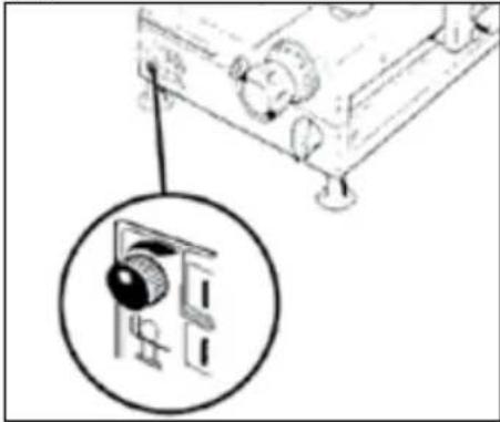
- place and remove the goods to be sliced on the sliding plate only with the carriage completely pulled back and with the thickness adjustment knob placed in the safety position (on the 0 position) (Fig. A);
- for movement of the meat table during cutting operations use only the handle located on the arm or the product presser grip;
- never put your hands on the food product while slicing. Always keep your hands behind the protection devices and far from the blade;
- use of cutting accessories which were not provided by the manufacturer with the machine is prohibited.
The manufacturer declines any responsibility coming from inappropriate use, modifications and/or repairs carried out by the user or unauthorized personnel, use of replacement parts that are not original or not specific for the machine model.
The machine shall not be used in open areas and/or areas which are exposed to atmospheric agents and in environments with vapors, fumes or corrosive and/or abrasive powders, with risk of fire or explosion and in any case where the
use of antiexplosive components is required.
Operating conditions:
- Temperature from
-5°C to +40°C
- Max. humidity 95%
DO NOT SLICE:
- frozen food products;
- food products with bones;
- any other product not intended for food use.
The safety ring around the blade is made in conformity to European standards EN 1974:1998+A1 but, in order to allow the sharpening operations, the protection in the sharpening area may not entirely eliminate the risk of cutting.
WARNING! During the blade cleaning and sharpening operations, pay extra attention to keep your hands as far as possible from the unprotected area. Use of protective gloves is recommended.
INSTALLATION OF THE MACHINE
Install the machine on a flat, smooth and dry surface suitable for supporting the weight of the machine itself plus the products to be sliced.
WARNING! Verify that there are no obstacles to the meat table travel and to the loading of products.
The machine must be installed in the immediate vicinity of an EEC standard outlet connected to an electrical supply system which is in conformity with the prevailing regulations for: - magneto-thermic protection;
- automatic differential switch; - earthing system.
Before carrying out electrical hook up verify that the characteristics of the electrical power supply is in accordance with those indicated on the machine information plate.
OPERATION
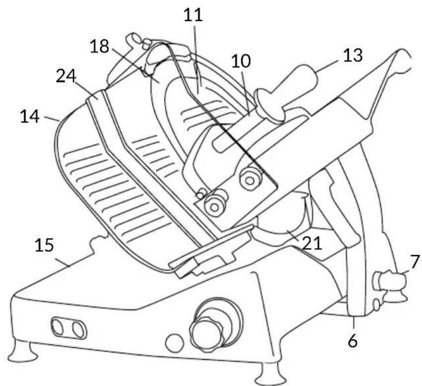
GL30: WARNING! Risk of injury from sharp blade! Check that the thickness adjustment knob (5) is in the safety position (on the 0 position) (Fig. A).
-
Pull the meat table (8) all the way back (towards the operator) in the loading position (Fig. B);
-
lift the product holder (17) into the standby position;
-
place the product to be sliced on the meat table near the operator side wall. Block it with the product holder applying slight pressure;
-
adjust the slice thickness. Activate the blade (10) by pressing the start button (1). Grip the product holder handle (9) and start an alternative cutting motion;
-
at the end of the cutting operations return the thickness adjustment knob to the safety position and pull the meat table back. Stop the blade motion by pressing the stop button (2).
AUTOMATIC OPERATION - FOR MODELS GL30A:
-
Rotate the carriage release grip (3) 180^ anticlockwise (3);
-
Press the blade start button (1b);
-
Press the meat table start button (1h).
-
To select the most suitable carriage travel for the shape of the product to be sliced, rotate the carriage extension (1a) in the clockwise direction to elongate and in the opposite direction to shorten (Fig. C).
WARNING! Do not place hands near the carriage or meat table while the machine is in operation.
Once cutting has been completed, press the meat table stop button (1f): the blade will keep running while the meat table will stop at the travel limit on the operator side, ready for more cutting.
If you press the blade stop button (n. 1e), the meat table will stop in its current position.
MANUAL OPERATION FOR SLC 300-330-350, SLC 350A: set the product to be sliced on the plate against the wall of the meat table, near the edge of the table on the operator side; lock using the product press holder, applying pressure; in the gravity version, the product will press against the plate from the force of its own weight;
- adjust the slice thickness with the special knob (3). Activate the blade (18) by pressing the start button (1). Grip the product holder handle (13) and start an alternative cutting motion;
- on gravity models, when the weight or size of the goods do not allow a proper cutting for reasons of gravity, use the product holder handgrip;
- at the end of the cutting operations return the thickness adjustment knob to the safety position and pull the meat ta-
ble back. Stop the blade motion by pressing the stop button (2); - move the sliding meat table away from the gauge plate and remove the product.
- Rotate the carriage release grip (3) 180^ anticlockwise (3);
- Press the blade start button (1b);
- Press the meat table start button (1h).
- To select the most suitable carriage travel for the shape of the product to be sliced, rotate the carriage extension (1a) in the clockwise direction to elongate and in the opposite direction to shorten (Fig. C).
WARNING! Do not place hands near the carriage or meat table while the machine is in operation.
Once cutting has been completed, press the meat table stop button (1f): the blade will keep running while the meat table will stop at the travel limit on the operator side, ready for more cutting.
If you press the blade stop button (n. 1e), the meat table will stop in its current position.
CLEANING
Before using, clean the machine at least once a day - or more often if necessary - and always after a long period of inactivity.
WARNING! Risk of electric shock! Before cleaning, disconnect the plug from the electrical mains socket and place the thickness adjustment knob in the safety position.
WARNING! Risk of injury from sharp blade! Check that the thickness adjustment knob (5) is in the safety position (on the 0 position) (Fig. A). DO NOT DISHWASH
Products for cleaning: use only water and biodegradable mild detergent, using a soft, spongy cloth and a semi-rigid nylon brush for the sharp areas of the plate and the product holder. Do not clean the machine with jets of water or steam or similar methods.
Dismantling:
- the meat table:
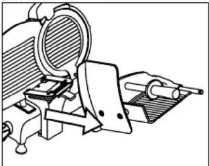
1) free the meat table, rotating the presser clamp in the clockwise direction. With the thickness adjustment knob in the safety position, pull back the carriage all the way until the travel limit toward the operator: a metallic click notifies the operator that the meat table is locked; 2) remove the product presser; 3) extract the product holder unit sliding the meat table from its support (Fig. D);
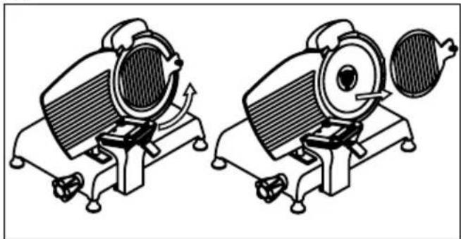
- the blade cover:
1) rotating in the anticlockwise direction, loosen the blade cover tension rod grip; 2) to raise the blade disc, press on the grip in the direction of the blade; 3) lift the blade cover (Fig. E);
- the slice deflector:
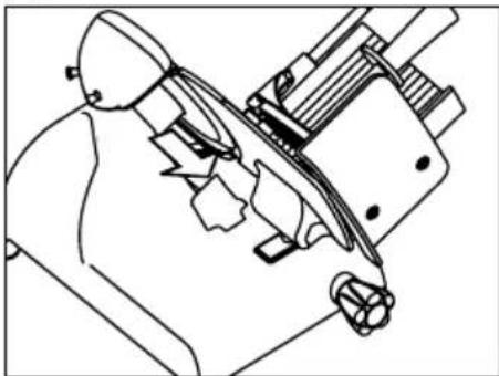
loosen the fixing screw and remove the slice deflector (Fig. F).
WARNING: Risk of injury from sharp blade! For the cleaning operations of the sharp areas of the plates, the product holder and the blade, use of protective gloves is also recommended.
Cleaning:
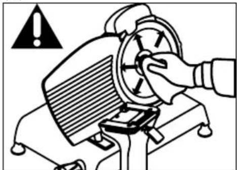
- the blade: press a damp cloth on the surface of the blade and move it slowly from the center toward the outside on the blade cover side and the opposite side (Fig. G). In the same way dry it using a dry cloth;
- the safety ring: use a soft brush to clean the area between the blade and the safety ring;
- the machine body: use a damp cloth or a sponge, rinsing water. Dry carefully.
MAINTENANCE
Blade Sharpening
Frequency and duration of sharpening depend on the use of the equipment.
WARNING! If the machine is equipped with its specific optional sharpener, follow the instructions. Otherwise, contact the manufacturer or to one of the Authorized Service Centers (see SERVICE).
For sharpening, follow the instructions:
- Position the thickness adjustment knob in the safety position (Fig. A);
- Pull the meat table all the way back (Fig. B);
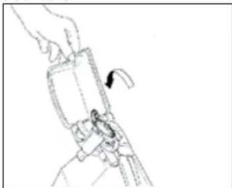
- Lift the sharpening device cover (Fig. L);
- Pull the release lever and rotate the sharpening device in the direction of the blade (Fig. M);
- Leave the lever. The device will lock in the correct position;
- Press the start button;
- Slightly rotate the lever, bringing the two wheels in contact with the blade and maintain the
position for about 10-15 seconds (Fig. N);
- Sharpening and deburring occur simultaneously;
- Stop the blade motion by pressing the stop button;
- Pull the lever to move the device back to the initial position;
- Lower the sharpening device guard cover;
- Proceed with cleaning the slicer.
Lubrication
After a regular period of use, it may be necessary to lubricate the carriage guides. We recommend executing this operation every 3 months. For lubrication, only use acid free oil (we recommend Vaseline oil). Do not use vegetable oil.
SERVICE
No user-serviceable parts are inside. Refer servicing to qualified personnel. All the repair and replacement operations (like blade replacement, replacement of the motor belt, replacement of the sub-basaplate electrical system components, repair of structural parts, repair and/or re-placement of sub-baseplate components, or similar) shall be executed exclusively by personnel authorized by the manufacturer.
In the event service is needed, you may return your food slicer to the manufacturer or to one of the Authorized Service Centers.
For information about service centers please contact us at: service@berkelinternational.com.
WARNING! The blade replacement is mandatory if distance between the edge of the blade and the internal edge of the guard exceeds 6 mm.
WARRANTY AND RESPONSIBILITY
The manufacturer supplies machines with a limited warranty of 24 months from the purchasing date. The warranty is extended only to defects that arise under intended use conditions and proper use. The warranty does not cover defects resulting from faults caused by transport, purchaser's incompetence or negligence, improper installation or earthing, unauthorised interventions, natural wear and tear, voltage variations greater than 10% of the nominal value. Moreover, the warranty does not cover components intrinsically subject to wear, such as blades and grinders, except in the event of evident manufacturing defects. The manufacturer declines any direct and indirect responsibility coming from:
- failure to observe the instructions in this manual;
- use which does not conform to prevailing specific regulations in the country of installation;
- unauthorised modifications and/or repairs carried out on the machine;
- use of non original accessories and replacement parts;
- exceptional events.
Transfer of ownership of the machine automatically defaults the manufacturer's liability for
the machine in question with the exception of observance of directive 2006/42/CE (liability for any manufacturing defects of the product).
The Identification tag on the base-plate indicates manufacturer, machine, technical information and CE marking.
DEMOLITION OF THE SLICER
The machines are comprised of:
- aluminum/magnesium alloy structure;
- inserts and various components and stainless steel;
- electrical parts and electrical cables;
- electric motor;
- plastic material, etc.
If dismantling and demolition are entrusted to third parties, use only companies authorized for disposal of the above-mentioned materials.
The appliance complies with the EU Directive 2012/19/UE. Packaging materials and appliances contain recyclable materials. Your appliance contains valuable materials that can be recovered or can be recyclable. Separation of the remaining waste materials into different types facilitates the recycling of valuable raw materials. Leave the appliances at a collection point. You can obtain information on disposal from your local authorities.
Troubleshooting
| PROBLEM REASON REMEDY | ||
| The machine does not start when the on button is pressed | Lack of power or defective control circuit | Check that the plug has been correctly inserted. If the machine still does not start, contact the Service Center |
| The machine starts when the on button is pressed but the operation indicator light does not turn on | The indicator light may be defective | Do not use the machine with the indicator light off. Contact the Service Center |
| Excessive resistance to cutting of the product | The blade is dull Sharpen the blade | blade |
| The blade slows down or stops while cutting the product | The drive belt may be loose or damaged | Contact the service center in order to tension or replace the belt |
| The machine does not stop when the stop button is pressed | The control circuit may be defective | Immediately stop the machine, removing the plug from the mains outlet. Contact the service center |
| Excessive resistance in motion of the sliding components (product holder, carriage) | The lubrication of the sliding guide may not be sufficient | Carry out periodical lubrication as described in this manual |
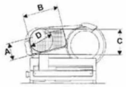
PRO LINE VS25 -VS30
| MODEL | VS25 VS30 | |
| E | 380 mm 400 mm | |
| F | 300 mm 300 mm | |
| G | 380 mm 420 mm | |
| H | 380 mm 380 mm | |
| I | 550 mm | 610 mm |
| SPECIFICATIONS | ||
| ø Blade | 250 mm | 300 mm |
| Cut thickness | 0 -14 mm 0 -14 mm | |
| Net weight | 17 kg | 20 kg |
| Cutting capacity (rect.) | 210x120 mm 210x160 mm | |
| Cutting capacity (circ.) | 165 mm | 200 mm |
| Motor rating | 0,20 kW | 0,20 kW |
| Specification electrical | 230 V - 50 Hz220 V - 60 Hz120 V 60 Hz | |
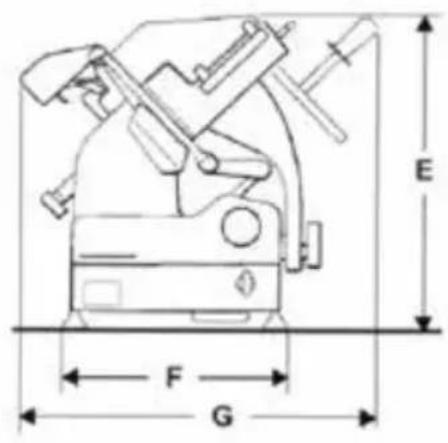
| MODEL GL30 | |
| A | 170 mm |
| B | 200 mm |
| C | 225 mm |
| D | 200 mm |
| E | 460 mm |
| F | 340 mm |
| G | 530 mm |
| H | 430 mm |
| I | 630 mm |
| SPECIFICATIONS | |
| ø Blade | 300 mm |
| Cut thickness | 0 -14 mm |
| Net weight | 25 kg |
| Cutting capacity (rect.) | 200x170 mm |
| Cutting capacity (circ.) | 200 mm |
| Motor rating | 0,20 - 0,30 kW |
| Specification electrical | 230 V 50 Hz | 220 V 60 Hz | 120 V 60 Hz |
PRO LINE GL30 AUTO
| MODEL GL30 AUTO | |
| A | 170 mm |
| B | 200 mm |
| C | 225 mm |
| D | 200 mm |
| E | 530 mm |
| F | 340 mm |
| G | 550 mm |
| H | 430 mm |
| I | 640 mm |
| SPECIFICATIONS | |
| ø Blade | 300 mm |
| Cut thickness | 0 -14 mm |
| Net weight | 41 kg |
| Cutting capacity (rect.) | 220x170 mm |
| Cutting capacity (circ.) | 200 mm |
| Motor rating | 0,40 kW |
| Specification electrical | 120 V 60 Hz - 230 V 50 Hz |
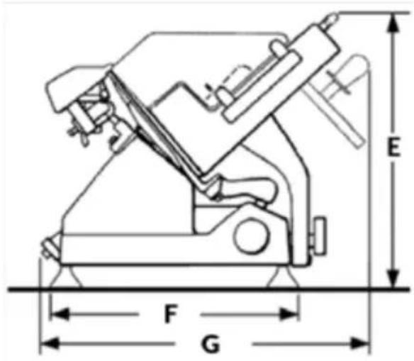
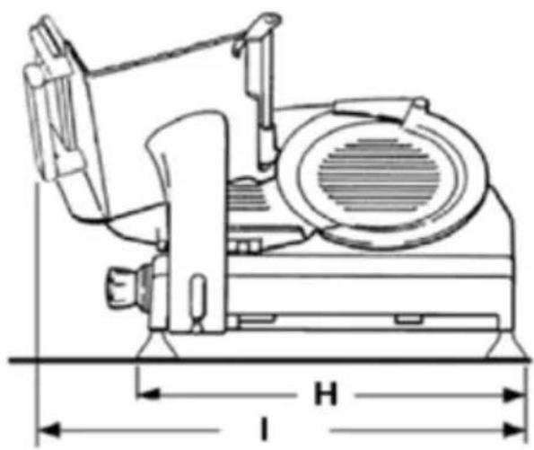
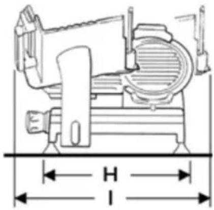
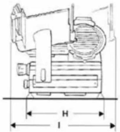
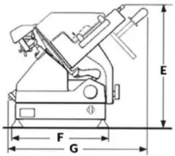
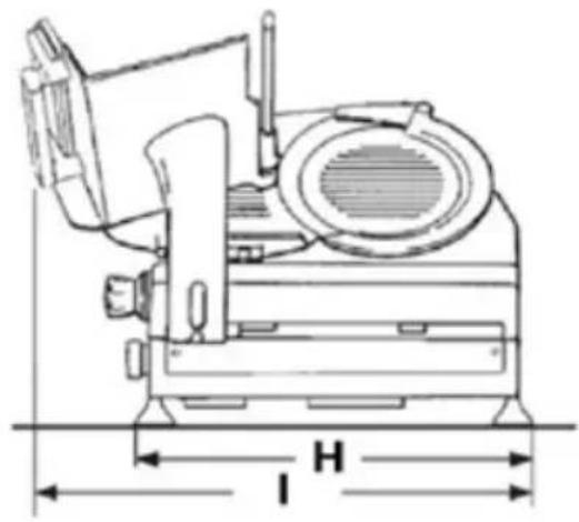
| MODEL SLC300 SLC330 SLC350 | |||
| E | 530 mm 530 mm 530 mm | ||
| F | 450 mm 450 mm 450 mm | ||
| G | 650 mm 670 mm 670 mm | ||
| H | 580 mm 580 mm 580 mm | ||
| I | 700 mm 740 mm | 730 mm | |
| SPECIFICATIONS | |||
| ø Blade | 300 mm 330 mm | 350 mm | |
| Cut thickness | 0 -14 0 -25 | 0 -14 | |
| Net weight | 41 kg 43 kg | 43 kg | |
| Cutting capacity (rect.) | 260x150h 280x170h | 260x190h | |
| Cutting capacity (circ.) | 210 mm 240 mm | 250 mm | |
| Motor rating | 0,30 kW 0,30 | 0,35 kW | 0,35 kW | |
| Specification electrical | 120/60/1 V - Hz230/50/1 v - Hz | 120/60/1 - 230/50/1 V - Hz220/60/1 - 400/50/3 V - Hz | 220/60/1 V - Hz400/50/3 V - Hz |
| MODEL SLCX MATIC 350 | |
| E | 620 mm |
| F | 430 mm |
| G | 650 mm |
| H | 570 mm |
| I | 700 - 760 mm |
| SPECIFICATIONS | |
| ø Blade | 350 mm |
| Cut thickness | 0 -14 |
| Net weight | 61 kg |
| Cutting capacity (rect.) | 250x190h |
| Cutting capacity (circ.) | 250 mm |
| Motor rating | 0,45 kW |
| Specification electrical | 230/50/1 V - Hz120/60/1 V - Hz |
Note: As we actually strive to improve our products, specifications are necessarily subject to change without notice.

COMPONENTI PRINCIPALI

SLC 300 - 330 - 350 SLC 350A
COMPONENTI PRINCIPALI


HAUPTBESTANDTEILE


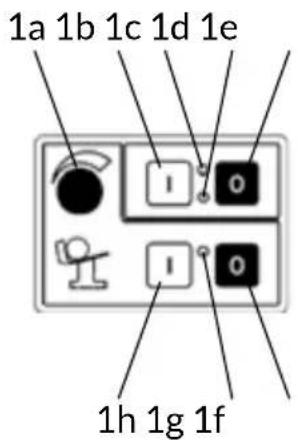
Fig. 2
SLC 300 - 330 - 350
SLC 350A
HAUPTBESTANDTEILE


Fig. 2
ÉLÉMENTS PRINCIPAUX
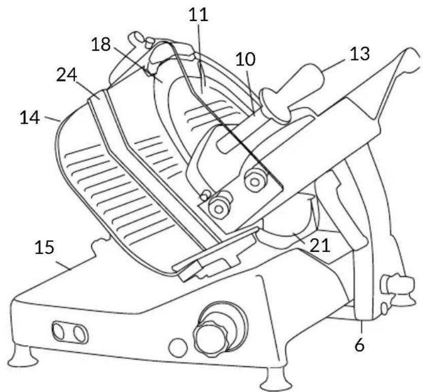

Fig. 2
SLC 300 - 330 - 350
SLC 350A
ÉLÉMENTS
PRINCIPAUX
DÉCLARATION DE CONFORMITÉ


ČÁSTI STROJE

SLC 300 - 330 - 350
SLC 350A
ČÁSTI STROJE


MASKINDELE
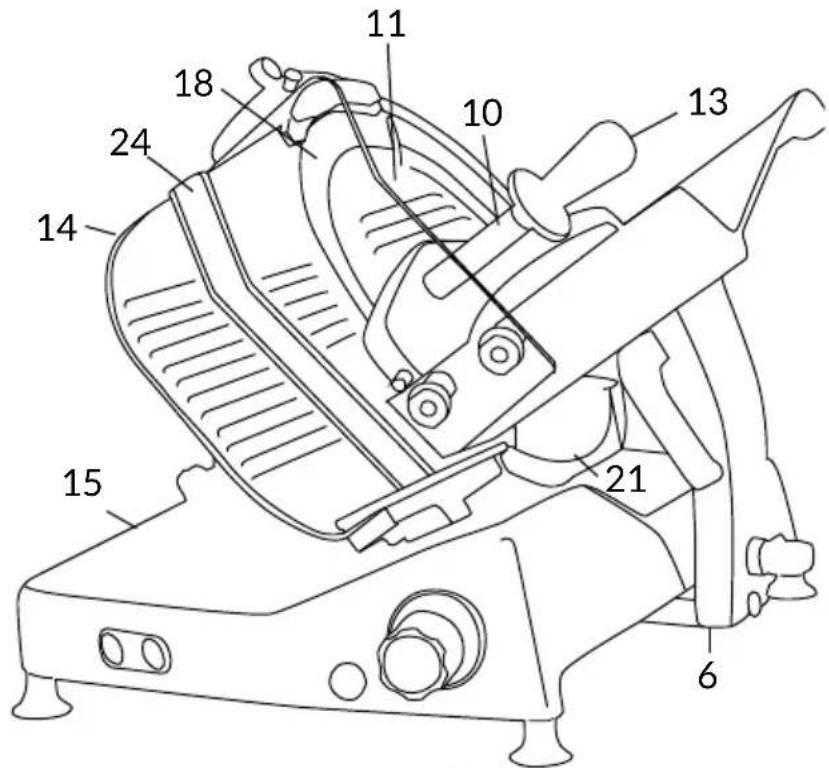
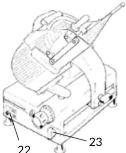

Fig. 2
SLC 300 - 330 - 350
SLC 350A
MASKINDELE


Fig. 2
COMPONENTES PRINCIPALES


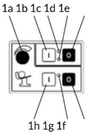
Fig. 2
SLC 300 - 330 - 350 SLC 350A
COMPONENTES PRINCIPALES


ONDERDELEN VAN DE MACHINE


SLC 300 - 330 - 350 SLC 350A
ONDERDELEN VAN DE MACHINE


MASKINDELER

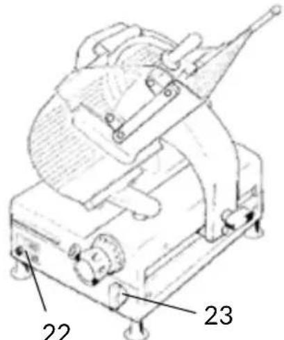

Fig. 2
SLC 300 - 330 - 350
SLC 350A
MASKINDELER


PARTES DA MÁQUINA


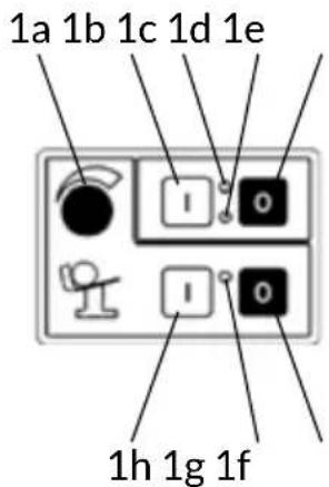
Fig. 2
SLC 300 - 330 - 350
SLC 350A
PARTES DA MÁQUINA
CUIDADO! Mantenha as


PĂRȚI ALE MAȘINII

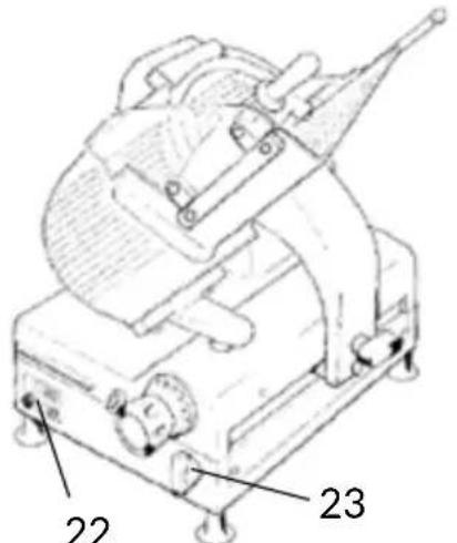
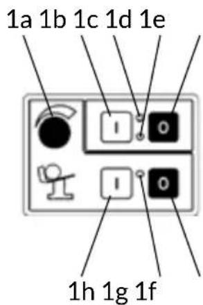
Fig. 2
EOG25 - EOG30 - EOG35
SLC 300 - 330 - 350
SLCX MATIC 350
PĂRȚI ALE MAȘINII

MASKINDELAR
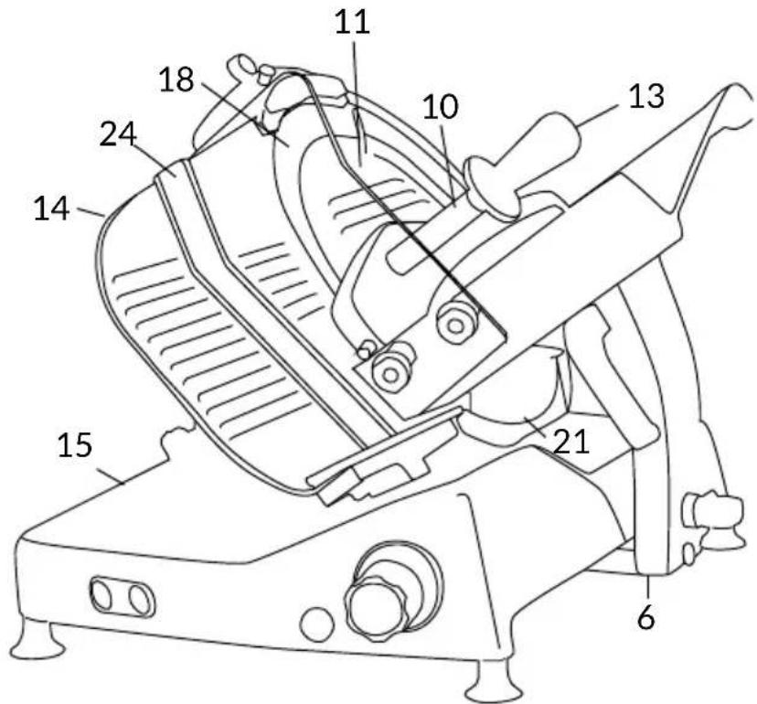
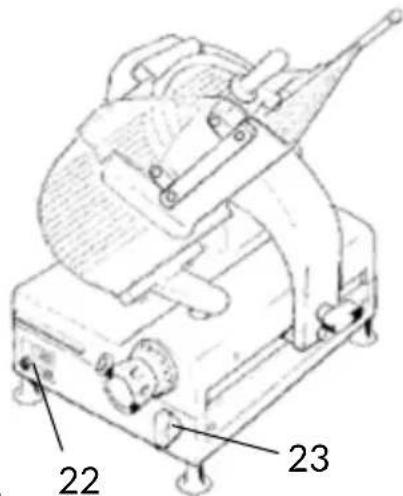

Bild. 2
SLC 300 - 330 - 350
SLC 350A