WELDPAK 140HD - Welding machine LINCOLN ELECTRIC - Free user manual and instructions
Find the device manual for free WELDPAK 140HD LINCOLN ELECTRIC in PDF.
| Product Type | DC Constant Current (CC) Welding Machine with Gasless Flux-Cored Wire |
| Brand | Lincoln Electric |
| Model | WELDPAK 140HD (WELD-PAK 90i FC) |
| Power Supply | 120 V AC, 60 Hz, Single Phase |
| Output Current | 30 A to 120 A |
| Open Circuit Voltage | 45 V |
| Duty Cycle | 30% at 90 A |
| Compatible Wire Diameter | 0.030 in (0.8 mm) and 0.035 in (0.9 mm) |
| Wire Feed Speed | 0 to 200 IPM (0 to 5.08 m/min) |
| Gross Weight | 7 kg (15 lb) |
| Protection Rating | IP21S |
| Thermal Protection | Yes, automatic shutdown in case of overheating |
| Welding Process | Gasless FCAW (Innershield flux-cored wire) |
| Included Accessories | Welding gun, work cable with clamp, drive roll, spare contact tip |
| Routine Maintenance | Regular cleaning of nozzle and contact tip |
| Available Spare Parts | Contact tip, drive roll, nozzle, wire guide |
| Recommended Consumable | Lincoln NR-211-MP wire (0.030 or 0.035 in) |
| Repairability | Reserved for qualified personnel; contact authorized after-sales service |
| Safety | Mandatory grounding, protection against electric shock and arcs |
Frequently Asked Questions - WELDPAK 140HD LINCOLN ELECTRIC
User questions about WELDPAK 140HD LINCOLN ELECTRIC
0 question about this device. Answer the ones you know or ask your own.
Ask a new question about this device
Download the instructions for your Welding machine in PDF format for free! Find your manual WELDPAK 140HD - LINCOLN ELECTRIC and take your electronic device back in hand. On this page are published all the documents necessary for the use of your device. WELDPAK 140HD by LINCOLN ELECTRIC.
USER MANUAL WELDPAK 140HD LINCOLN ELECTRIC
natural_image
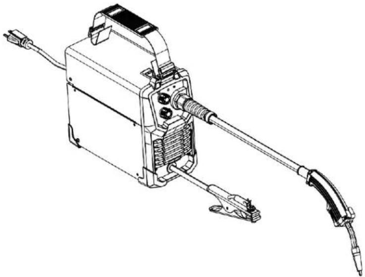
Technical line drawing of a mechanical device with attached cable and spring (no text or symbols)For use with Product Numbers:
13397

Register your machine:
www.lincolnelectric.com/register
Authorized Service and Distributor Locator:
www.lincolnelectric.com/locator
Save for future reference
Date Purchased
Code: (ex: 10859)
Serial: (ex: U1060512345)
Need Help? Call 1.888.935.3877
to talk to a Service Representative
Hours of Operation:
8:00 AM to 6:00 PM (ET) Mon. thru Fri.
After hours?
Use "Ask the Experts" at lincolnelectric.com
A Lincoln Service Representative will contact you no later than the following business day.
For Service outside the USA:
Email: globalservice@lincolnelectric.com
THANK YOU FOR SELECTING A QUALITY PRODUCT BY LINCOLNELECTRIC.
PLEASE EXAMINE CARTON AND EQUIPMENT FOR DAMAGE IMMEDIATELY
When this equipment is shipped, title passes to the purchaser upon receipt by the carrier. Consequently, claims for material damaged in shipment must be made by the purchaser against the transportation company at the time the shipment is received.
SAFETY DEPENDS ON YOU
Lincoln arc welding and cutting equipment is designed and built with safety in mind. However, your overall safety can be increased by proper installation ... and thoughtful operation on your part. DO NOT INSTALL, OPERATE OR REPAIR THIS EQUIPMENT WITHOUT READING THIS MANUAL AND THE SAFETY PRECAUTIONS CONTAINED THROUGHOUT. And, most importantly, think before you act and be careful.

WARNING
This statement appears where the information must be followed exactly to avoid serious personal injury or loss of life.

CAUTION
This statement appears where the information must be followed to avoid minor personal injury or damage to this equipment.
KEEP YOUR HEAD OUT OF THE FUMES.
DON'T get too close to the arc. Use corrective lenses if necessary to stay a reasonable distance away from the arc.
READ and obey the Safety Data Sheet (SDS) and the warning label that appears on all containers of welding materials.
USE ENOUGH VENTILATION or exhaust at the arc, or both, to keep the fumes and gases from your breathing zone and the general area.
natural_image
Illustration of a person in protective gear using a UV light to observe or test equipment (no text or symbols visible)IN A LARGE ROOM OR OUTDOORS, natural ventilation may be adequate if you keep your head out of the fumes (See below).
USE NATURAL DRAFTS or fans to keep the fumes away from your face.
If you de velop unusual symptoms, see your supervisor. Perhaps the welding atmosphere and ventilation system should be checked.

natural_image
Silhouette of a person wearing a welding helmet and holding a tool, no text or symbols presentWEAR CORRECT EYE, EAR & BODY PROTECTION
PROTECT your eyes and face with welding helmet properly fitted and with proper grade of filter plate (See ANSI Z49.1).
PROTECT your body from welding spatter and arc flash with protective clothing including woolen clothing, flame-proof apron and gloves, leather leggings, and high boots.
PROTECT others from splatter, flash, and glare with protective screens or barriers.
IN SOME AREAS, protection from noise may be appropriate.
BE SURE protective equipment is in good condition.
Also, wear safety glasses in work area AT ALL TIMES.
SPECIAL SITUATIONS
DO NOT WELD OR CUT containers or materials which previously had been in contact with hazardous substances unless they are properly cleaned. This is extremely dangerous.
DO NOT WELD OR CUT painted or plated parts unless special precautions with ventilation have been taken. They can release highly toxic fumes or gases.
Additional precautionary measures
PROTECT compressed gas cylinders from excessive heat, mechanical shocks, and arcs; fasten cylinders so they cannot fall.
BE SURE cylinders are never grounded or part of an electrical circuit.
REMOVE all potential fire hazards from welding area.
ALWAYS HAVE FIRE FIGHTING EQUIPMENT READY FOR IMMEDIATE USE AND KNOW HOW TO USE IT.

SECTION A: WARNINGS

CALIFORNIA PROPOSITION 65 WARNINGS

WARNING: Breathing diesel engine exhaust exposes you to chemicals known to the State of California to cause cancer and birth defects, or other reproductive harm.
- Always start and operate the engine in a well-ventilated area.
- If in an exposed area, vent the exhaust to the outside.
- Do not modify or tamper with the exhaust system.
- Do not idle the engine except as necessary.
For more information go to www.P65 warnings.ca.gov/diesel
WARNING: This product, when used for welding or cutting, produces fumes or gases which contain chemicals known to the State of California to cause birth defects and, in some cases, cancer. (California Health & Safety Code § 25249.5 et seq.)

WARNING: Cancer and Reproductive Harm www.P65warnings.ca.gov
ARC WELDING CAN BE HAZARDOUS. PROTECT YOURSELF AND OTHERS FROM POSSIBLE SERIOUS INJURY OR DEATH. KEEP CHILDREN AWAY. PACEMAKER WEARERS SHOULD CONSULT WITH THEIR DOCTOR BEFORE OPERATING.
Read and understand the following safety highlights. For additional safety information, it is strongly recommended that you purchase a copy of "Safety in Welding & Cutting - ANSI Standard Z49.1" from the American Welding Society, P.O. Box 351040, Miami, Florida 33135 or CSA Standard W117.2. A Free copy of "Arc Welding Safety" booklet E205 is available from the Lincoln Electric Company, 22801 St. Clair Avenue, Cleveland, Ohio 44117-1199.
BE SURE THAT ALL INSTALLATION, OPERATION, MAINTENANCE AND REPAIR PROCEDURES ARE PERFORMED ONLY BY QUALIFIED INDIVIDUALS.

FOR ENGINE POWERED EQUIPMENT.
1.a. Turn the engine off before troubleshooting and maintenance work unless the maintenance work requires it to be running.

1.b. Operate engines in open, well-ventilated areas or vent the engine exhaust fumes outdoors.
1.c. Do not add the fuel near an open flame welding arc or when the engine is running. Stop the engine and allow it to cool before refueling to prevent spilled fuel from vaporizing on contact

with hot engine parts and igniting. Do not spill fuel when filling tank. If fuel is spilled, wipe it up and do not start engine until fumes have been eliminated.
1.d. Keep all equipment safety guards, covers and devices in position and in good repair. Keep hands, hair, clothing and tools away from V-belts, gears, fans and all other moving parts when starting, operating or repairing equipment.

1.e. In some cases it may be necessary to remove safety guards to perform required maintenance. Remove guards only when necessary and replace them when the maintenance requiring their removal is complete. Always use the greatest care when working near moving parts.
1.f. Do not put your hands near the engine fan. Do not attempt to override the governor or idler by pushing on the throttle control rods while the engine is running.
1.g. To prevent accidentally starting gasoline engines while turning the engine or welding generator during maintenance work, disconnect the spark plug wires, distributor cap or magneto wire as appropriate.
1.h. To avoid scalding, do not remove the radiator pressure cap when the engine is hot.
1.i. Using a generator indoors CAN KILL YOU IN MINUTES.
1.j. Generator exhaust contains carbon monoxide. This is a poison you cannot see or smell.
1.k. NEVER use inside a home or garage, EVEN IF doors and windows are open.
1.I. Only use OUTSIDE and far away from windows, doors and vents.
1.m. Avoid other generator hazards. READ MANUAL BEFORE USE.

text_image
Diagram showing three scenarios of a house with no signage, including a parking sign and a car stop sign.
ELECTRIC AND MAGNETIC FIELDS MAY BE DANGEROUS
2.a. Electric current flowing through any conductor causes localized Electric and Magnetic Fields (EMF). Welding current creates EMF fields around welding cables and welding machines
2.b. EMF fields may interfere with some pacemakers, and welders having a pacemaker should consult their physician before welding.
2.c. Exposure to EMF fields in welding may have other health effects which are now not known.
2.d. All welders should use the following procedures in order to minimize exposure to EMF fields from the welding circuit:
2.d.1. Route the electrode and work cables together - Secure them with tape when possible.
2.d.2. Never coil the electrode lead around your body.
2.d.3. Do not place your body between the electrode and work cables. If the electrode cable is on your right side, the work cable should also be on your right side.
2.d.4. Connect the work cable to the workpiece as close as possible to the area being welded.
2.d.5. Do not work next to welding power source.

ELECTRIC SHOCK CAN KILL.

3.a. The electrode and work (or ground) circuits are electrically "hot" when the welder is on. Do
not touch these "hot" parts with your bare skin or wet clothing. Wear dry, hole-free gloves to insulate hands.
3.b. Insulate yourself from work and ground using dry insulation. Make certain the insulation is large enough to cover your full area of physical contact with work and ground.
In addition to the normal safety precautions, if welding must be performed under electrically hazardous conditions (in damp locations or while wearing wet clothing; on metal structures such as floors, gratings or scaffolds; when in cramped positions such as sitting, kneeling or lying, if there is a high risk of unavoidable or accidental contact with the workpiece or ground) use the following equipment:
- Semiautomatic DC Constant Voltage (Wire) Welder.
• DC Manual (Stick) Welder.
• AC Welder with Reduced Voltage Control.
3.c. In semiautomatic or automatic wire welding, the electrode, electrode reel, welding head, nozzle or semiautomatic welding gun are also electrically "hot".
3.d. Always be sure the work cable makes a good electrical connection with the metal being welded. The connection should be as close as possible to the area being welded.
3.e. Ground the work or metal to be welded to a good electrical (earth) ground.
3.f. Maintain the electrode holder, work clamp, welding cable and welding machine in good, safe operating condition. Replace damaged insulation.
3.g. Never dip the electrode in water for cooling.
3.h. Never simultaneously touch electrically "hot" parts of electrode holders connected to two welders because voltage between the two can be the total of the open circuit voltage of both welders.
3.i. When working above floor level, use a safety belt to protect yourself from a fall should you get a shock.
3.j. Also see It ems 6.c. and 8.

ARC RAYS CAN BURN.
4.a. Use a shield with the proper filter and cover plates to protect your eyes from sparks and the rays of the arc when welding or observing open arc welding. Headshield and filter lens should conform to ANSI Z87. I standards.
4.b. Use suitable clothing made from durable flame-resistant material to protect your skin and that of your helpers from the arc rays.
4.c. Protect other nearby personnel with suitable, non-flammable screening and/or warn them not to watch the arc nor expose themselves to the arc rays or to hot spatter or metal.

5.a. Welding may produce fumes and gases hazardous to health. Avoid breathing these fumes and gases. When welding, keep your head out of the fume. Use enough ventilation and/or exhaust at the arc to keep fumes and gases away from the breathing zone. When welding hardfacing (see instructions on container or SDS) or on lead or cadmium plated steel and other metals or coatings which produce highly toxic fumes, keep exposure as low as possible and within applicable OSHA PEL and ACGIH TLV limits using local exhaust or mechanical ventilation unless exposure assessments indicate otherwise. In confined spaces or in some circumstances, outdoors, a respirator may also be required. Additional precautions are also required when welding on galvanized steel.
- b. The operation of welding fume control equipment is affected by various factors including proper use and positioning of the equipment, maintenance of the equipment and the specific welding procedure and application involved. Worker exposure level should be checked upon installation and periodically thereafter to be certain it is within applicable OSHA PEL and ACGIH TLV limits.
5.c. Do not weld in locations near chlorinated hydrocarbon vapors coming from degreasing, cleaning or spraying operations. The heat and rays of the arc can react with solvent vapors to form phosgene, a highly toxic gas, and other irritating products.
5.d. Shielding gases used for arc welding can displace air and cause injury or death. Always use enough ventilation, especially in confined areas, to insure breathing air is safe.
5.e. Read and understand the manufacturer's instructions for this equipment and the consumables to be used, including the Safety Data Sheet (SDS) and follow your employer's safety practices. SDS forms are available from your welding distributor or from the manufacturer.
5.f. Also see item 1.b.

WELDING AND CUTTING SPARKS CAN CAUSE FIRE OR EXPLOSION.
6.a. Remove fire hazards from the welding area. If this is not possible, cover them to prevent the welding sparks from starting a fire. Remember that welding sparks and hot materials from welding can easily go through small cracks and openings to adjacent areas. Avoid welding near hydraulic lines. Have a fire extinguisher readily available.
6.b. Where compressed gases are to be used at the job site, special precautions should be used to prevent hazardous situations. Refer to "Safety in Welding and Cutting" (ANSI Standard Z49.1) and the operating information for the equipment being used.
6.c. When not welding, make certain no part of the electrode circuit is touching the work or ground. Accidental contact can cause overheating and create a fire hazard.
6.d. Do not heat, cut or weld tanks, drums or containers until the proper steps have been taken to insure that such procedures will not cause flammable or toxic vapors from substances inside. They can cause an explosion even though they have been "cleaned". For information, purchase "Recommended Safe Practices for the Preparation for Welding and Cutting of Containers and Piping That Have Held Hazardous Substances", AWS F4.1 from the American Welding Society (see address above).
6.e. Vent hollow castings or containers before heating, cutting or welding. They may explode.
6.f. Sparks and spatter are thrown from the welding arc. Wear oil free protective garments such as leather gloves, heavy shirt, cuffless trousers, high shoes and a cap over your hair. Wear ear plugs when welding out of position or in confined places. Always wear safety glasses with side shields when in a welding area.
6.g. Connect the work cable to the work as close to the welding area as practical. Work cables connected to the building framework or other locations away from the welding area increase the possibility of the welding current passing through lifting chains, crane cables or other alternate circuits. This can create fire hazards or overheat lifting chains or cables until they fail.
6.h. Also see item 1.c.
6.I. Read and follow NFPA 51B "Standard for Fire Prevention During Welding, Cutting and Other Hot Work", available from NFPA, 1 Batterymarch Park, PO box 9101, Quincy, MA 022690-9101.
6.j. Do not use a welding power source for pipe thawing.

CYLINDER MAY EXPLODE IF DAMAGED.
7.a. Use only compressed gas cylinders containing the correct shielding gas for the process used and properly operating regulators designed for the gas and pressure used. All hoses, fittings, etc. should be suitable for the application and maintained in good condition.
7.b. Always keep cylinders in an upright position securely chained to an undercarriage or fixed support.
7.c. Cylinders should be located:
- Away from areas where they may be struck or subjected to physical damage.
- A safe distance from arc welding or cutting operations and any other source of heat, sparks, or flame.
7.d. Never allow the electrode, electrode holder or any other electrically "hot" parts to touch a cylinder.
7.e. Keep your head and face away from the cylinder valve outlet when opening the cylinder valve.
7.f. Valve protection caps should always be in place and hand tight except when the cylinder is in use or connected for use.
7.g. Read and follow the instructions on compressed gas cylinders, associated equipment, and CGA publication P-I, "Precautions for Safe Handling of Compressed Gases in Cylinders," available from the Compressed Gas Association, 14501 George Carter Way Chantilly, VA 20151.

FOR ELECTRICALLY POWERED EQUIPMENT.

8.a. Turn off input power using the disconnect switch at the fuse box before working on the equipment.
8.b. Install equipment in accordance with the U.S. National Electrical Code, all local codes and the manufacturer's recommendations.
8.c. Ground the equipment in accordance with the U.S. National Electrical Code and the manufacturer's recommendations.
Refer to
http://www.lincolnelectric.com/safety for additional safety information.
TABLE OF CONTENTS
Product Description .... 3
Installation 4
Technical Specifications....4
Premium Features....4
Select Suitable Location....5
Grinding 5
Stacking 5
Transport – Unloading ....5
Tilting 5
Environmental Rating 5
Input Connections 6
Wire Loading And Threading....7
Operation 9
Operating Machine 10
Replacement Parts Lists....11
Maintenance....12
Routine And Periodic Maintenance 12
Troubleshooting....12
How To Use Troubleshooting Guide....12
PRODUCT DESCRIPTION
PRODUCT SUMMARY
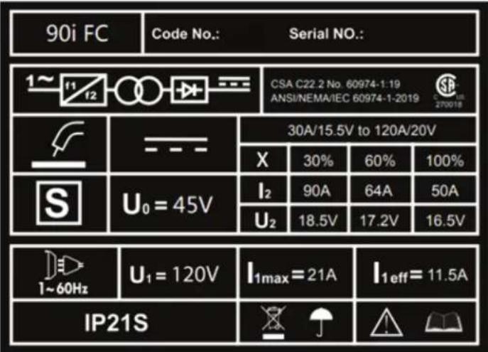
The Weld-Pak® 90i FC is a constant voltage DC welding machine rated for 90 amps, 18.5 volts at a 30% duty cycle. The Weld-Pak® unit is intended for fabrication, maintenance, home, and autobody shops. The unit features a portable and rugged case. The user interface features two knobs, one for voltage and one for wire feed speed. The Weld-Pak® 90i FC is designed for the North American market and operates on 120V single phase 60 Hz power. An overview of the machines input and output capabilities are listed on the rating plate shown here.
The machine comes with the following accessories:
- WP150L gun
• Work cable with clamp - Spare contact tips
• Procedure Chart and literature
text_image
90i FC Code No.: Serial NO.: 1~f1 f2 CSA C22.2 No. 60974-1:19 ANSI/NEMA/IEC 60974-1-2019 270018 30A/15.5V to 120A/20V X 30% 60% 100% S U₀ = 45V I₂ 90A 64A 50A U₂ 18.5V 17.2V 16.5V I₁max = 21A I₁eff = 11.5A IP21SINSTALLATION
TECHNICAL SPECIFICATIONS - K5255-1 WELD-PAK 90i FC
| OUTPUT CURRENT RANGE |
| 30-120A |
| OPEN CIRCUIT VOLTAGE |
| 46V (RMS) |
| INPUT CIRCUIT |
| 120VAC |
| DUTY CYCLE |
| 30%@90A |
| WIREFEED SPEED |
| 0 - 200 IPM |
| SUITABLE WIRE DIAMETER |
| 0.030", 0.035" |
| GROSS WEIGHT |
| 15 LBS (7KGS) |
| IPS RATING |
| IP21S |
PREMIUM FEATURES INCLUDE:
- Inverter power source – more efficient to operate, provides smoother weld characteristics than traditional welders
- Infinite welding voltage to allow fine tuning of weld characteristics
- 30% Duty cycle at 90 Amps
- Lightweight and portable – Ideal for maintenance and mobile welders
THERMAL PROTECTION
The machine has a maximum output duty cycle of 30%. If the duty cycle is exceeded, a thermal protector will shut off the output until the machine cools to a normal operating temperature. This is an automatic function of the machine and does not require user intervention.
REQUIRED ACCESSORIES
- Helmet
- Jacket
- Gloves
Read this entire installation section before you start installation.
Safety Precautions
Do not attempt to use this equipment until you have thoroughly read all installation, operating and maintenance information supplied with your equipment. They include important safety precautions and detailed operating and maintenance instructions.

WARNING
ELECTRIC SHOCK can kill.
- Only qualified personnel should perform this installation.
- Do not touch electrically live parts.
• Always connect the machine to an earthed mains supply.

SELECT SUITABLE LOCATION
Place the welder where clean cooling air can freely circulate in and out of the front & rear louver vents. Dirt, dust or any foreign material that can be drawn through vents into welder must be kept to a minimum. Failure to observe these precautions can result in excessive operating temperatures which can lead to plant failure.
GRINDING
Do not direct grinding particles towards the welder. An abundance of conductive material can cause plant failure.
STACKING
This machine cannot be stacked.
TRANSPORT - UNLOADING
Never underestimate the weight of equipment, never move or leave suspended in the air above people. The machine should be lifted and carried by the provided strap, or by cradling the machine. The machine should not be carried by the input, cord, output cables, or welding gun. Utilize proper lifting techniques when carrying or lifting the machine to prevent injury.

WARNING
Falling Equipment can cause injury. Never lift welder with gas bottle attached. Never lift above personnel.
TILTING
Machine must be placed on a secure level surface
ENVIRONMENTAL RATING
The welding power source carries the IP21S rating. It may be used in normal industrial and commercial environments. Avoid using in areas where water / rain is around.
Read and follow the ‘Electric Shock Warnings’ in the safety section if welding must be performed under electrically hazardous conditions such as welding in wet areas or water on the work piece.

WARNING
ELECTRIC SHOCK can kill.
• This welder must be grounded to earth


CAUTION
The high frequency generator being similar to a radio transmitter may cause interference to radio, TV and other electronic equipment.
- These problems may be the result of radiated interference. Proper grounding methods can reduce or eliminate this.
Radiated interference can develop in the following ways
- Direct interference from welder power source
- Direct interference from the welding leads
- Direct interference radiated from feedback into power lines
- Interference from re-radiation by un-grounded metallic objects
Keeping these contributing factors in mind, installing equipment as per following instructions should minimize problems
- Keep the welder input power lines as short as possible and enclose as much of them as possible in metal conduit or equivalent shielding. There should be a good electrical contact between this conduit and ground (Earth)
- Keep the work and electrode leads as short as possible. Tape the leads together where practical
- Be sure the torch and earth leads rubber coverings are free from cuts and cracks that allow welding power leakage
- Keep earth lead connection to work in good condition – Clean area on workbench where earth clamp is situated on a regular basis.
INPUT POWER CONNECTION
The machine has one input connection, the power input cable. The power input cable is located on the rear.
The Weld-Pak 90i FC is provided with a 120V cable, 6.0ft. (1.8m) in length, with a 15Amp 5-15P plug molded onto the cord.
The rated output of the Weld-Pak 90i FC is available when connected to a 20A branch circuit. When connected to a branch circuit with lower capacity, lower welding current and duty cycle must be used.
CODE REQUIREMENTS FOR ELECTRICAL INPUT CONNECTIONS

WARNING
This welding machine must be connected to a power source in accordance with applicable electrical codes.
The National Electrical Code provides standards for amperage handling capability of supply conductors based on duty cycle of the welding source.
If there is any question about the installation meeting applicable electrical code requirements, consult a qualified electrician.

WARNING
Do not connect the machine to an input power supply with a rated voltage that is greater than 125 volts.
Do not remove the power cord ground prong.
EXTENSION CORD USAGE
If an extension cord is required, use one that is rated for the application and is 3 conductor #14 AWG (2.1 mm2) or larger. The recommended maximum lengths are 25 ft (7.5 m) if #14 AWG (2.1 mm2) is used and 50 ft (15 m) if #12 AWG (3.3 mm2) is used.
FLUX-CORED (INNERSHIELD) WELDING
The recommended electrode for the flux-cored, self-shielded process is 0.035" (0.9 mm) diameter Lincoln Innershield NR-211-MP on 1 lbs. (.5 kg) spools.
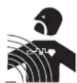
FIGURE 1
text_image
Technical diagram of a portable electrical device with numbered components for identification- Adjustment for Voltage
- Adjustment for Wire feed speed
- Power and protection LEDs
- Gasless Flux-Cored torch
- Work Clamp
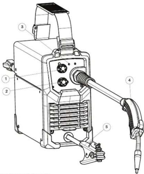
text_image
Technical diagram of an electrical device with numbered parts labeled 6, 7, and 8- Power Switch
- Power Input Cable
- Spool cover latch
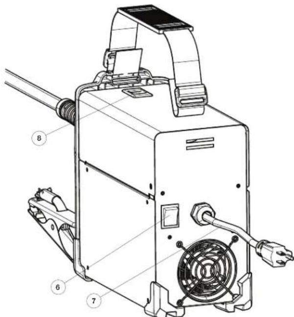
WIRE LOADING AND THREADING
Refer to Figure 2.
Turn machine power switch to the OFF ("0") position before working inside the wire feed enclosure.
Make sure that the wire feed drive roll and the contact tip of the gun match the diameter and type of wire used.
- Push the spool onto the spindle so that the wire feeds off the bottom of the spool, toward the drive roll.
- Push the spool spacer onto the spindle, against the spool.
- Slide the spring onto the spool, then press on the spool lock, turning it clockwise to lock the spool assembly onto the spindle.
FIGURE 2
text_image
Spool Lock & Spring Cap Spool Spacer Spool Note Wire Direction Spindle Cold Feed SwitchWIRE THREADING DETAILS
Refer to Figure 3.
- Release the spring loaded thumb screw and rotate the idle roll arm away from the wire feed drive roll. Ensure that the visible, stenciled size on the drive roll side facing you matches the wire size being used.
- Carefully detach the end of the wire from the spool. Maintain tension on the wire to prevent the spool from unwinding and do not release the wire until after step 5.
- Cut the bent portion of wire off and straighten the first 4" (100 mm).
- Thread the wire through the incoming guide tube, over the drive roll, and into the gun liner.
- Close the idle roll arm and turn down the thumbscrew until the idle roller presses down firmly on the wire. (Now you may release the welding wire). Make sure the wire is positioned in the groove of the lower drive roll.
- The spring loaded thumbscrew on the idle roll arm adjusts the pressure on the wire. Adjust pressure by turning the thumbscrew to prevent spool overrun, but still allow smooth and easy wire feeding. Start with the pressure set to an intermediate value. Readjust, if necessary. If the drive roll slips while feeding wire, the pressure should be increased until the wire feeds properly.
FIGURE 3
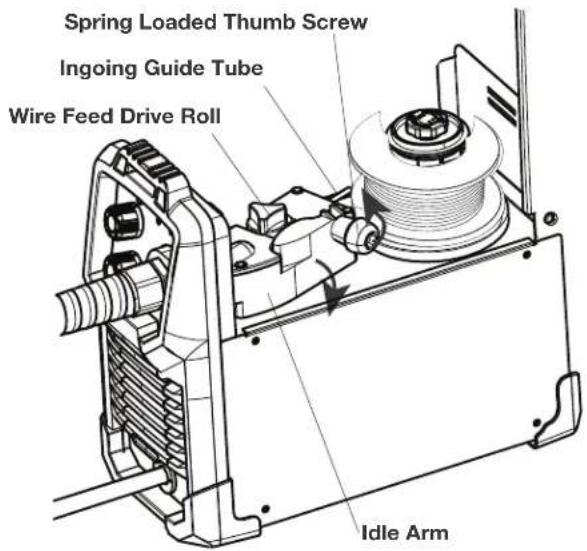
text_image
Spring Loaded Thumb Screw Ingoing Guide Tube Wire Feed Drive Roll Idle ArmWIRE STICKOUT
- Remove the contact tip and nozzle from the gun.
- Turn the machine ON ("I").
- Straighten the gun cable assembly.
- Depress the cold feed switch and feed welding wire through the gun and cable. (Point the gun away from yourself and others while feeding wire). Release the cold feed switch after wire appears at the end of the gun.
- Turn off the machine.
- Replace the nozzle and contact tip. Refer to Figure B-4. Cut the wire off so that 3/8" to 5/8" (10 - 15 mm) protrudes from the end of the tip.
- Turn on the machine. The machine is now ready to weld.
FIGURE 4
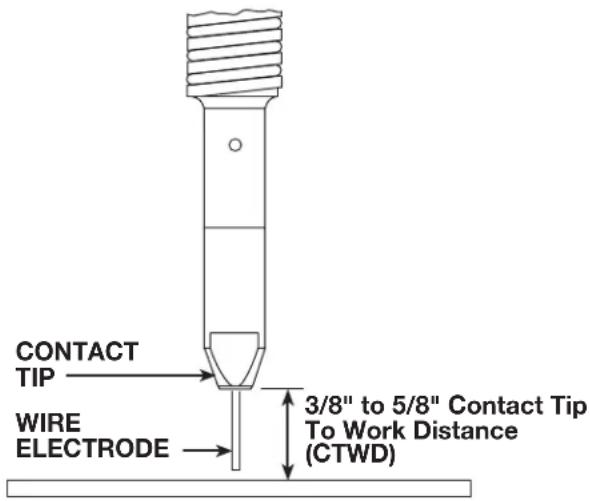
text_image
CONTACT TIP WIRE ELECTRODE 3/8" to 5/8" Contact Tip To Work Distance (CTWD)OPERATION
Read and understand this entire section before operating your CrossLinc Remote.
GRAPHIC SYMBOLS USED IN THIS MANUAL OR BY THIS MACHINE

text_image
INPUT POWER ON OFF HIGH TEMPERATURE CIRCUIT BREAKER WIRE FEEDER POSITIVE OUTPUT NEGATIVE OUTPUT INVERTER INPUT POWER DIRECT CURRENT U0 U1 U2 I1 I2 PROTECTIVE GROUND WARNING or CAUTION Explosion Dangerous Voltage Shock HazardsnoituacerP ytefaS
Do not attempt to use this equipment until you have thoroughly read all operating and maintenance manuals supplied with your equipment and any related welding machine it will be used with. They include important safety precautions, operating and maintenance instructions and parts lists.

WARNING
ELECTRIC SHOCK can kill.
- Do not touch electrically live parts such as output terminals or internal wiring.
• Insulate yourself from the work and ground.
• Always wear dry insulating gloves.

WELDING SPARKS can cause fire or explosion.
- Keep flammable material away.
- Do not weld upon containers which have held combustibles.
ARC RAYS can burn.
- Wear eye, ear and body protection.
FUMES AND GASES can be dangerous.
Although the removal of the particulate matter from welding smoke may reduce the ventilation requirement, concentrations of the clear exhausted fumes and gases may still be hazardous to health. Avoid breathing concentrations of these fumes and gases. Use adequate ventilation when welding. See ANSI Z49.1, "Safety in Welding and Cutting", published by the American Welding Society.

OPERATING MACHINE
Once you have set machine up as per instructions, refer to Table B.1 and the Procedure Decal located on the inside of the wire drive compartment door of your machine for setup information, consumables, and quick tips for welding.
- Select welding voltage (power), based on the material thickness of the work piece, required on front panel
- Select wire feed speed required on 'wire speed' knob
- Ensure you are wearing the correct safety clothes & equipment for welding (I.E Welding mask, gloves, apron etc)
FIGURE 5
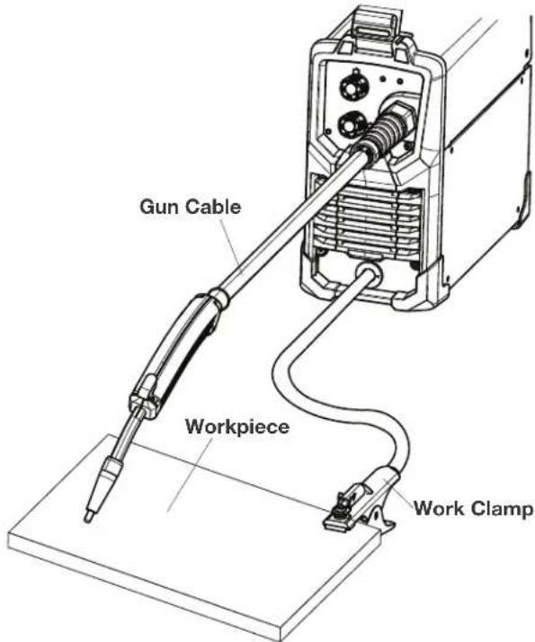
text_image
Gun Cable Workpiece Work Clamp- Connect the work clamp to the metal to be welded. The work clamp must make good electrical contact to the work piece. The work piece must also be grounded as stated in Arc Welding Safety Precautions in the beginning of this manual.
- Based on the weld joint type and orientation of the weld joint, position the gun into the joint at the correct angle.
- To begin welding, raise your hand shield or lower your helmet to protect your eyes and pull the trigger.
- While welding, travel at a constant speed and maintain an electrode stickout of 3/8".
- To stop welding, release the gun trigger.
- When no more welding is to be done, turn off the machine.
TABLE B.1
| FCAW -Gasless (Flux Cored) | |||||||
| Welding Wire | .030 Lincoln NR-211-MP (Innershield Cored Wire) | .035 Lincoln NR-211-MP (Innershield Cored Wire) | |||||
| Contact Tip | .030 (0.8mm) - Lincoln Part No. KH711 | .035 (0.9mm) - Lincoln Part No. KH712 | |||||
| Drive Roll | 0.030/0.035 (0.8mm/0.9mm) Knurled groove - Lincoln Part No. KP4364-035 | ||||||
| Loading The Wire | Remember: Remove the contact tip prior to loading wireKeep tension on the wire to prevent unspooling. | ||||||
| 1. Cutoff the bent portion of the wire and straighten the first 4" for feeding into rolls and gun.2. Release spring loaded pressure arm and rotate the Idle Roll Arm away from Drive Roll.3. Thread wire through the guide tube, over drive roll and into gun liner. Close Idle Roll arm. | |||||||
| Wire Feed Tension | The suggested Wro Feed Speed settings in the table below are based on a midrange wire tension setting. The tension may be changed if required to improved wire feeding; however, the WFS setting may have to be adjusted from the values in the table below. | ||||||
| Suggested Settings For Welding | NO GAS WITH NR-211 WIRE | 20ga 0.9mm | 18ga 1.2mm | 16ga 1.6mm | 14ga 2.1mm | 1/8"ga 3.2mm | |
| 0.030 NR-211 | Voltage | 1.5 | 2.5 | 3 | 4 | 6 | |
| WFS | 3.5 | 5 | 7 | 8 | 10 | ||
| 0.035 NR-211 | Voltage | -- | 2 | 3 | 4 | 6 | |
| WFS | -- | 3 | 4.5 | 6 | 10 | ||
| Helpful Hints | Weld at a Steady PaceDo NOT weave the arc, neither forward, backward, or sidewaysRemove Slag with the Chipping Hammer to expose weldFor Horizontal Weld Joints, remember: "Drag If there's Slag"Refer to Manual for Troubleshooting Poor Weld Quality | ||||||
| Direction of Welding AND Angle of Gun relative to Weld Direction | Horizontal: "Drag" | Vertical (in | Vertical (in | ||||
| Proper Gun Angles for common Weld Joint Types | Tee Joint | 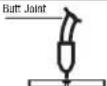 | 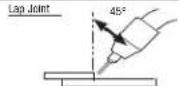 | ||||
| Electrical Stickout | Maintain an electrode Stickout of 3/8" while welding. | CONTACT TIFELECTRODE | |||||
REPLACE PARTS LIST
| Contact Tip (.030") | KH711 (.030" / 0.8MM) |
| Contact Tip (.035") | KH712 (.035" / 0.9MM) |
| Drive Roll | KP4364-035 |
| Nozzle | KH726 |
| FCAW Wire | LINCOLN .030 NR-211-MP |
| FCAW Wire | LINCOLN .035 NR-211-MP |

WARNING
Use of this unit on thicker materials than recommended may result in welds of poor quality. The welds may appear to be fine, but may lack the fusion or bonding necessary to give a strong weld. This is called "Cold Casting" or "cold lapping" and is some what similar to a cold solder joint. Weld failure may result.
MAINTENANCE

WARNING
ELECTRIC SHOCK can kill.
- Turn the input power OFF at the welding power source before installation or changing drive rolls and/or guides.
- Do not touch electrically live parts.
- When inching with the gun trigger, electrode and drive mechanism are "hot" to work and ground and could remain energized several seconds after the gun trigger is released.
- Do not operate with covers, panels or guards re moved or open.
- Only qualified personnel should perform maintenance work.

ITEMS REQUIRING NO MAINTENANCE
- Drive Motor and Gearbox – Lifetime lubrication
- Wire Reel Spindle – Do NOT lubricate shaft
ROUTINE AND PERIODIC MAINTENANCE
- BEFORE EACH USE - Check over machine and accessories for any obvious condition that may prevent safe performance or operation. Repair or replace items as necessary to correct any abnormal condition.
AFTER 5 MINUTES OF WELDING OR WHEN SPATTER ACCUMULATES ON THE CONTACT TIP:
- CLEANING TIP AND NOZZLE - With the power switch in the off position, keep the contact tip and nozzle clean to avoid arc bridging between them. Bridging can result in a shorted nozzle, poor welds and an overheated gun. Hint: Anti-stick spray or gel, available from a welding supplier, may reduce buildup and aid in spatter removal.
TROUBLESHOOTING
HOW TO USE TROUBLESHOOTING GUIDE

WARNING
Service and Repair should only be performed by Lincoln Electric Factory Trained Personnel. Unauthorized repairs performed on this equipment may result in danger to the technician and machine operator and will invalidate your factory warranty. For your safety and to avoid Electrical Shock, please observe all safety notes and precautions detailed throughout this manual.
This Troubleshooting Guide is provided to help you locate and repair possible machine malfunctions. Simply follow the three-step procedure listed below.
Step 1. LOCATE PROBLEM (SYMPTOM).
Look under the column labeled “PROBLEM (SYMPTOMS).” This column describes possible symptoms that the machine may exhibit. Find the listing that best describes the symptom that the machine is exhibiting.
Step 2. POSSIBLE CAUSE.
The second column labeled "POSSIBLE CAUSE" lists the obvious external possibilities that may contribute to the machine symptom.
Step 3. RECOMMENDED COURSE OF ACTION
This column provides a course of action for the Possible Cause, generally it states to contact you local Lincoln Authorized Field Service Facility.
If you do not understand or are unable to perform the Recommended Course of Action safely, contact your local Lincoln Authorized Field Service Facility.

WARNING
ELECTRIC SHOCK can kill.
- Turn off machine at the disconnect switch on the rear of the machine and remove main power supply connections before doing any troubleshooting.

Observe all Safety Guidelines detailed throughout this manual
| PROBLEM (SYMPTOMS) | POSSIBLE AREAS OF MISADJUSTMENT(S) | RECOMMENDED COURSE OF ACTION |
| Bead is too thick (intermittently). | Travel speed is slow and/or inconsistent. Increase and maintain a constant travel speed. | |
| Output heat range is too high. Turn the voltage down. | ||
| Bead does not penetrate base metal. | Travel speed is inconsistent. Decrease and maintain a constant travel speed. | |
| Output heat range is too low. Turn the voltage up. | ||
| Wire sputters and sticks to workpiece. | The wire is damp. Change to dry wire. Be sure wire is stored in a dry location | |
| Wire feed speed (WFS) is too fast. Reduce WFS. | ||
| Edge of weld has ragged depressions. | Travel speed is too fast. Reduce travel speed. | |
| WFS is too fast. Reduce WFS. | ||
| Output heat range is too high. Set the Low – High Heat Range switch to Low or the Fine Heat Adjustment to (1). | ||
text_image
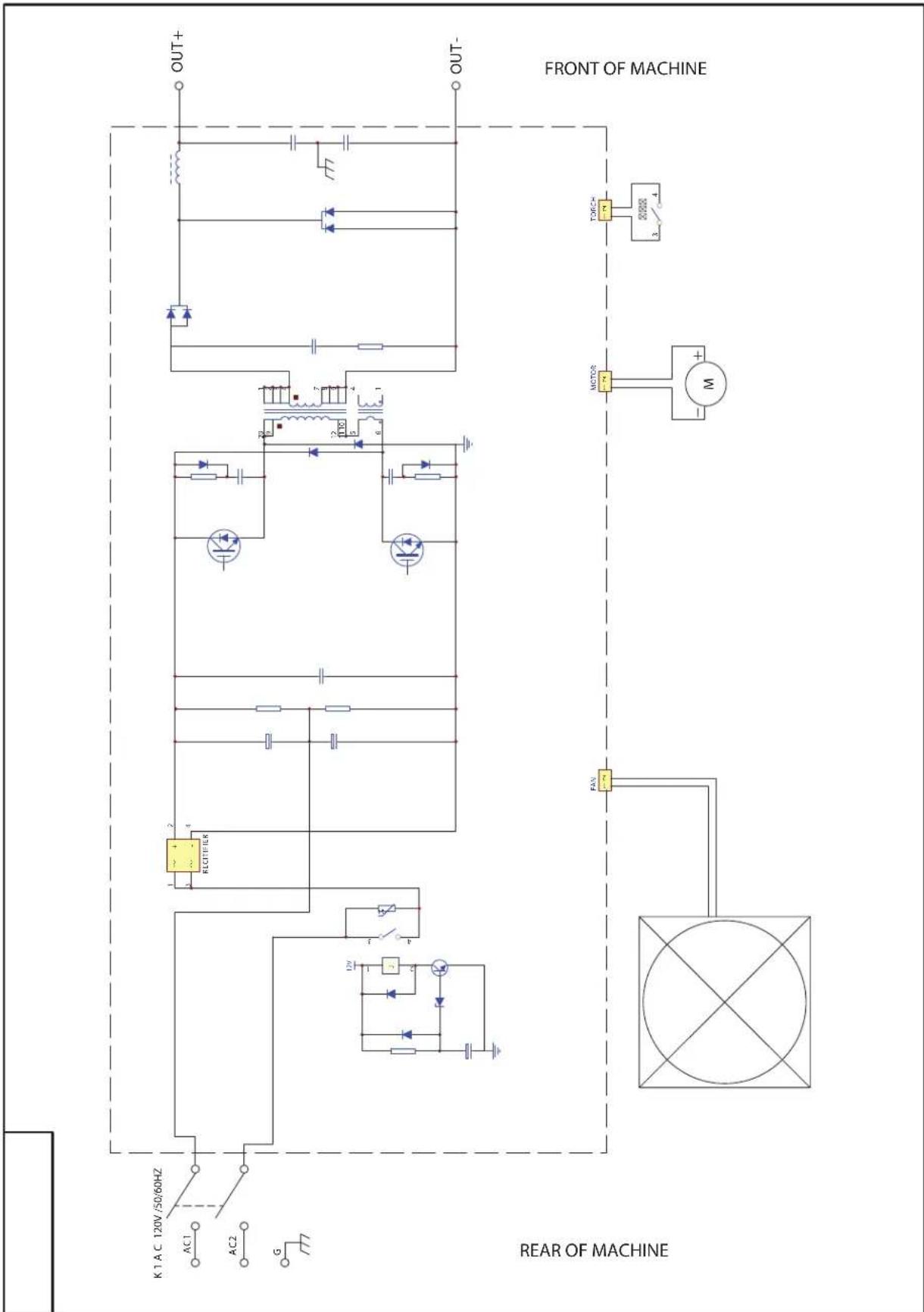
K1 AC 120V /50/60HZ AC1 AC2 G REAR OF MACHINE RECOUNTER OUT+ OUT- FAN MOTOR TORCH 3 4 FRONT OF MACHINE |  |  |  |
| WARNING | Do not touch electrically live parts or electrode with skin or wet clothingInsulate yourself from work and ground. | Keep flammable materials away. | Wear eye, ear and body protection. |
| SpanishAVISO DE PRECAUCION | No toque las partes o los electrodos bajo carga con la piel o ropa moja-da.Aislese del trabajo y de la tierra. | Mantenga el material combustible fuera del área de trabajo. | Protéjase los ojos, los oídos y el cuerpo. |
| FrenchATTENTION | Ne laissez ni la peau ni des vête-ments mouillés entrer en contact avec des pièces sous tension.Isolez-vous du travail et de la terre. | Gardez à l'écart de tout matériel inflammable. | Protégez vos yeux, vos oreilles et votre corps. |
| GermanWARNUNG | Berühren Sie keine stromführenden Teile oder Elektroden mit Ihrem Körper oder feuchter Kleidung!Isolieren Sie sich von den Elektroden und dem Erdboden! | Entfernen Sie brennbarres Material! | Tragen Sie Augen-, Ohren- und Kör-perschutz! |
| PortugueseATENÇÃO | Não toque partes elétricas e elec-trodos com a pele ou roupa molha-da.Isole-se da peça e terra. | Mantenha inflamáveis bem guarda-dos. | Use proteção para a vista, ouvido e corpo. |
| Japanese注意事項 | 通電中の電気部品、又は溶材にヒフやぬれた布で触れないこと。施工物やアースから身体が絶縁されている様にして下さい。 | 燃えやすいものの側での溶接作業は絶対にしてはなりません。 | 目、耳及び身体に保護具をして下さい。 |
| Chinese警告 | 皮肤或濕衣物切勿接觸帶電部件及錚條。使你自己與地面和工件絶縁。 | 把一切易燃物品移離工作場所。 | 佩戴眼、耳及身體勞動保護用具。 |
| Korean위험 | 전도체나 용접봉을 젖은 형갑 또는 피부로 절대 접촉치 마십시오 모재와 접지를 접촉치 마십시오. | 인화성 물질을 접근 시키지 마시요. | 눈, 귀와 몇에 보호장구를 착용하십시오. |
| Arabicتحذير | لا تلمس الاجزاء التي يسري فيها التيارال.ceربائي أو الالكترود بجلد الجسم أو بالعلابس المبللة بالมาณ.UGH عازلا على جسمك خلال العمل. | ضع #: ضع #: ضع #: ضع #: ضع #: ضع #: ضع #: ضع #: ضع #: ضع #: ضع #: ضع #: ضع #: ضع #: ضع #: ضع #: ضع #: ضع #: ضع #: ضع #: ضع #: ضع #: ضع #: ضع #: ضع #: ضع #: ضع #: ضع #: ضع #: ضع #: ضع #: ضع #: ضع #: ضع #: ضع#: ضع #: ضع #: ضع #: ضع #: ضع #: ضع #: ضع #: ضع #: ضع #: ضع #: ضع #: ضع #: ضع #: ضع #: ضع #: ضع #: ضع #: ضع #: ضع #: ضع #: ضع #: ضع #: ضع #: ضع #: ضع #: ضع #: ضع #: ضع #: ضع #: ضع #: ضع #: ضع #: ضع #: Sunshine: Sunshine: Sunshine: Sunshine: Sunshine: Sunshine: Sunshine: Sunshine: Sunshine: Sunshine: Sunshine: Sunshine: Sunshine: Sunshine: Sunshine: Sunshine: Sunshine: Sunshine: Sunshine: Sunshine: Sunshine: Sunshine: Sunshine: Sunshine: Sunshine: Sunshine: Sunshine: Sunshine: Sunshine: Sunshine: Sunshine: Sunshine: Sunshine: Sunshine: Sunshine: Sunshine: Sunshine: Sunshine: Sunshine: Sunshine: Sunshine: Sunshine: Sunshine: Sunshine: Sunshine: Sunshine: Sunshine: Sunshine: Sunshine: Sunshine: Sunshine; Sunshine: Sunshine: Sunshine: Sunshine: Sunshine: Sunshine: Sunshine: Sunshine: Sunshine: Sunshine: Sunshine: Sunshine: Sunshine: Sunshine: Sunshine: Sunshine: Sunshine: Sunshine: Sunshine: Sunshine: Sunshine: Sunshine: Sunshine: Sunshine: Sunshine: Sunshine: Sunshine: Sunshine: Sunshine: Sunshine: Sunshine: Sunshine: Sunshine: Sunshine: Sunshine: Sunshine: Sunshine: Sunshine: Sunshine: Sunshine: Sunshine: Sunshine: Sunshine: Sunshine: Sunshine: Sunshine: Sunshine: Sunshine: Sunshine: Sunshine : Sunshine : Sunshine : Sunshine : Sunshine : Sunshine : Sunshine : Sunshine : Sunshine : Sunshine : Sunshine : Sunshine : Sunshine : Sunshine : Sunshine : Sunshine : Sunshine : Sunshine : Sunshine : Sunshine : Sunshine : Sunshine : Sunshine : Sunshine : Sunshine : Sunshine : Sunshine : Sunshine : Sunshine : Sunshine : Sunshine : Sunshine : Sunshine : Sunshine : Sunshine : Sunshine : Sunshine : Sunshine : Sunshine : Sunshine : Sunshine : Sunshine : Sunshine : Sunshine : Sunshine : Sunshine : Sunshine : Sunshine : Sunshine : Sunshine : Sunshine . Sunshine : Sunshine : Sunshine : Sunshine : Sunshine : Sunshine : Sunshine : Sunshine : Sunshine : Sunshine : Sunshine : Sunshine : Sunshine : Sunshine : Sunshine : Sunshine : Sunshine : Sunshine : Sunshine : Sunshine : Sunshine : Sunshine : Sunshine : Sunshine : Sunshine : Sunshine : Sunshine : Sunshine : Sunshine : Sunshine : Sunshine : Sunshine : Sunshine : Sunshine : Sunshine : Sunshine : Sunshine : Sunshine : Sunshine : Sunshine : Sunshine : Sunshine : Sunshine : Sunshine : Sunshine : Sunshine : Sunshine : Sunshine : Sunshine : Sunshine |
READ AND UNDERSTAND THE MANUFACTURER'S INSTRUCTION FOR THIS EQUIPMENT AND THE CONSUMABLES TO BE USED AND FOLLOW YOUR EMPLOYER'S SAFETY PRACTICES.
CUSTOMER ASSISTANCE POLICY
The business of Lincoln Electric is manufacturing and selling high quality welding equipment, automated welding systems, consumables, and cutting equipment. Our challenge is to meet the needs of our customers, who are experts in their fields, and to exceed their expectations. On occasion, purchasers may ask Lincoln Electric for information or technical information about their use of our products. Our employees respond to inquiries to the best of their ability based on information and specifications provided to them by the customers and the knowledge they may have concerning the application. Our employees, however, are not in a position to verify the information provided or to evaluate the engineering requirements for the particular weldment, or to provide engineering advice in relation to a specific situation or application. Accordingly, Lincoln Electric does not warrant or guarantee or assume any liability with respect to such information or communications. Moreover, the provision of such information or technical information does not create, expand, or alter any warranty on our products. Any express or implied warranty that might arise from the information or technical information, including any implied warranty of merchantability or any warranty of fitness for any customers' particular purpose or any other equivalent or similar warranty is specifically disclaimed.
Lincoln Electric is a responsive manufacturer, but the definition of specifications, and the selection and use of specific products sold by Lincoln Electric is solely within the control of, and remains the sole responsibility of the customer. Many variables beyond the control of Lincoln Electric affect the results obtained in applying these types of fabrication methods and service requirements.
WELD FUME CONTROL EQUIPMENT
The operation of welding fume control equipment is affected by various factors including proper use and positioning of the equipment, maintenance of the equipment and the specific welding procedure and application involved. Worker exposure level should be checked upon installation and periodically thereafter to be certain it is within applicable OSHA PEL and ACGIH TLV limits.

THE LINCOLN ELECTRIC COMPANY
22801 St. Clair Avenue • Cleveland, OH • 44117-1199 • U.S.A.
Phone: +1.216.481.8100 • www.lincolnelectric.com
WELD-PAK 90i FC
natural_image
Technical line drawing of a mechanical device with attached probe and cable (no text or symbols)natural_image
Illustration of a person in protective gear using a welding torch to lift a red flame (no text or symbols)natural_image
Silhouette of a person in a welding uniform holding a tool, no text or symbols presentPORTEZ DES DISPOSITIFS DE PROTECTION ADÉQUATS POUR LES YEUX, LES OREILLES ET LE CORPS.
AVERTISSEMENT : Cancer and Reproductive Harm www.P65warnings.ca.gov
LE SOUDAGE À L'ARC PEUT ÊTRE DANGEREUX. PROTÉGEZ-VOUS ET D'AUTRES PERSONNES CONTRE DES BLESSURES GRAVES OU MORTELLES. GARDEZ LES ENFANTS À L'ÉCART. LES PORTEURS DE STIMULATEURS CARDIAQUES DOIVENT CONSULTER LEUR MÉDECIN AVANT D'UTILISER LE PRODUIT.
text_image
Diagram showing three house shapes with no parking, a car, and a vehicle icon, likely indicating parking or parking-related restrictions.
LES CHAMPS ÉLECTRIQUES ET MAGNETIQUES PEUVENT ÊTRE DANGEREUX

SOUDAGE À L'ARC AVEC FIL FOURRÉ (INNERSHIELD)
text_image
Technical diagram of a portable air purifier with numbered components and Chinese label at bottomtext_image
Technical diagram of an electrical device with numbered components labeled 6, 7, and 8natural_image
Technical line drawing of a mechanical device with attached probe and cable (no text or symbols)natural_image
Illustration of a person in protective gear using a tool on a workbench, with no visible text or symbols.natural_image
Silhouette of a person wearing a welding helmet and holding equipment (no text or symbols)text_image
Diagram showing three scenarios of a vehicle with no parking, including a house and a car, with a rightward arrow indicating direction.
LOS CAMPOS ELÉCTRICOS Y MAGNÉTICOS PUEDEN SER PELIGROSOS