SG20RT - Battery charger Sungrow - Free user manual and instructions
Find the device manual for free SG20RT Sungrow in PDF.

| Product Type | Hybrid solar inverter (integrated battery charger) |
| Brand | Sungrow |
| Model | SG20RT |
| Rated Power | 20 kW |
| Max PV Input Voltage | 1000 V DC |
| Output Voltage | 400 V AC three-phase |
| Output Frequency | 50/60 Hz |
| Max Efficiency | 98.7% |
| Power Supply | Grid and photovoltaic panels |
| Main Functions | DC/AC conversion, battery charging, energy management, monitoring via app |
| Protection | Overcurrent, overvoltage, ground fault, anti-islanding, IP65 protection |
| Protection Rating | IP65 (suitable for outdoor use) |
| Display | Integrated LCD screen |
| Communication | Wi-Fi, RS485, Ethernet (depending on module) |
| Weight | Approximately 35 kg |
| Dimensions (W x H x D) | 520 x 640 x 270 mm |
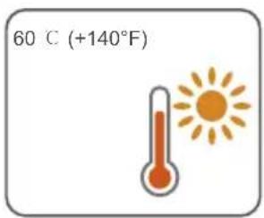
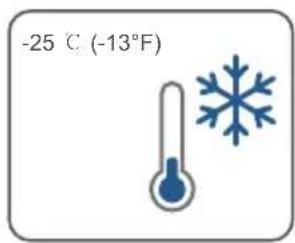
| Operating Temperature | -25°C to +60°C |
| Maintenance | Cleaning heatsinks, checking cables and connections |
| Safety | Emergency stop, galvanic disconnection, mandatory grounding |
| Compliance | CE, UKCA, TUV, RoHS |
| Installation | For qualified personnel only |
Frequently Asked Questions - SG20RT Sungrow
User questions about SG20RT Sungrow
0 question about this device. Answer the ones you know or ask your own.
Ask a new question about this device
Download the instructions for your Battery charger in PDF format for free! Find your manual SG20RT - Sungrow and take your electronic device back in hand. On this page are published all the documents necessary for the use of your device. SG20RT by Sungrow.
USER MANUAL SG20RT Sungrow
3-Phase PV Grid-Connected Inverter
Quick Installation Guide
SG3.0RT / SG4.0RT / SG5.0RT / SG6.0RT / SG7.0RT
SG8.0RT / SG10RT / SG12RT / SG15RT / SG17RT
SG20RT / SG5.0RT-P2 / SG6.0RT-P2 / SG7.0RT-P2
SG8.0RT-P2 / SG10RT-P2 / SG12RT-P2 / SG15RT-P2
SG17RT-P2 / SG20RT-P2
EN
- The Contents may be periodically updated or revised due to product development. The information in this guide is subject to change without notice. In no case shall this guide substitute for the user manual or related notes on the device.
- Make sure to read over, fully understand and strictly follow the detailed instructions of the user manual and other related regulations before installing the equipment. The user manual can be downloaded by visiting the website at http://support.sunrowpower.com/; or it can be obtained by scanning the QR code on the side of the equipment or the back cover of this guide.
- All installations must be performed by qualified personnel who should have training for installation and commissioning of electrical system, as well as dealing with hazards, have knowledge of the manual and of the local regulations and directives.
- Before installation, check that the package contents are intact and complete compared to the packing list. Contact SUNGROW or the distributor in case of any damaged or missing components.
- The cable used must be intact and well insulated. Operation personnel must wear proper personal protective equipment (PPE) all the time.
Any violation could result in personal death or injury or device damage, and will void the warranty.
Safety
The inverter has been designed and tested strictly according to international safety regulations. Read all safety instructions carefully prior to any work and observe them at all times when working on or with the inverter. Incorrect operation or work may cause:
- injury or death to the operator or a third party;
damage to the inverter and other properties.
Please follow the safety instructions related to the PV strings and the utility grid.

DANGER
Lethal voltage!
- PV strings will produce electrical power when exposed to sunlight and can cause a lethal voltage and an electric shock.
- Only qualified personnel can perform the wiring of the PV panels.

NOTICE
Danger to life from electric shock due to lethal voltage!
- All electrical connections must be in accordance with local and national standards.
- Only with the permission of the utility grid, the inverter can be connected to the utility grid.
Inverter
The icons on the inverter body are as follows.

Disconnect the inverter from all the external power sources before maintenance!

Read the user manual before maintenance!
Burn danger due to hot surface that may exceed 60^ .
RCM mark of conformity.
| Danger to life due to high voltages! Only qualified personnel can open and maintain the inverter. | Danger to life due to high voltages! Do not touch live parts for 10 minutes after disconnection from the power sources. Only qualified personnel can open and service the inverter. |
| TÜV mark of conformity. | CE CE mark of conformity. EU/EEA Importer. |
| Do not dispose of the inverter together with household waste. | The inverter does not have a transformer. |
| Additional grounding point. UKCA mark of conformity. | UKCA |
| RoHS labeling The product complies with the requirements of the applicable EU directives. | CMIM-Prüfzeichen. |
Users may also attach other warning signs as per the requirements of the local standards or installation specifications.
Security Declaration
For details on the product's network security vulnerability response process and vulnerability disclosure, please scan the QR code on the right or visit the following website: https://en.sungrowpower.com/security-vulnerability-management
For more information on network security, please refer to the user manual of the communication module or the Data Logger that comes with the product.
EU Declaration of Conformity
within the scope of the EU directives:
Low Voltage Directive 2014/35/EU (LVD)
Electromagnetic compatibility Directive 2014/30/EU (EMC)
- Restriction of the use of certain hazardous substances 2011/65/EU and 2015/863/EU (RoHS)
The manufacturer Sungrow Power Supply Co., Ltd, China hereby confirms that the product SG3.0-20RT&SG5.0-20RT-P2 complies with the essential requirements and other relevant provisions of Directives 2014/35/EU, 2014/30/EU, 2011/65/EU, 2015/863/EU. The full EU Declaration of Conformity can be found at https://support.sungrowpower.com/PdfDetail?id=1697881433535078402.
The communication module that comes with the inverter and the technical parameters of wireless communication are listed in the table below. The model of the communication module actually delivered shall prevail. The EU Declaration of Conformity for the communication module can be found at support.sungrowpower.com .
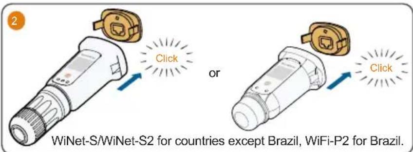
WiNet-S/WiNet-S2:
Technologie radio WLANI 802.11b/g/n20/n40
Radio spectrum
802.11b/g/n
2412 MHz 2472 MHz
802.11n40
2422 MHz ~ 2462 MHz
Maximum transmitted power ≤ 20 dBm
Technical parameters listed above apply to EU countries only.
Manufacturer:
Sungrow Power Supply Co., Ltd.
No 1699. Xiyou Road, Hefei 230088.P.R China
For EU only
EU/EEA Importer:
Danger to life from electric shocks due to live voltage
Do not open the enclosure at any time. Unauthorized opening will void warranty and warranty claims and in most cases terminate the operating license.
- When the enclosure lid is removed, live components can be touched which can result in death or serious injury due to electric shock.
Lethal danger from electric shock due to possibly damaged inverter
- Only operate the inverter when it is technically faultless and in a safe state.
- Operating a damaged inverter can lead to hazardous situations that can result in death or serious injuries due to electric shock.

WARNING
Risk of inverter damage or personal injury
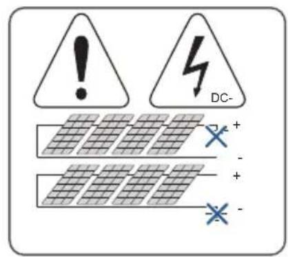
- Do not connect or disconnect the PV and AC connectors when the inverter is running.
- Wait at least 10 minutes for the internal capacitors to discharge after all electric devices are removed and the inverter is powered off.
- Ensure that there is no voltage or current before connecting or disconnecting the PV and AC connectors.

WARNING
All the warning labels and nameplate on the inverter body:
- must be clearly visible; and
- must not be removed, covered or pasted.

CAUTION
Risk of burns due to hot components!
Do not touch any hot parts (such as the heat sinks) during operation. Only the DC switch can safely be touched at any time.

NOTICE
Only qualified personnel can perform the country setting. Unauthorized alteration may cause a breach of the type-certificat. marking.
Risk of inverter damage due to electrostatic discharge (ESD)!
By touching the electronic components, you may damage the inverter. For inverter handling, be sure to:
- avoid any unnecessary touching; and
- wear a grounding wristband before touching any connectors.
DE
Sungrow Power Supply Co., Ltd.
Nr. 1699. Xiyou Road, Hefei 230088.P.R.China
Nur fur die EU
Sungrow Power Supply Co., Ltd.
No 1699. Xiyou Road, Hefei 230088. R. P. Cinese
Solo per l'UE
Importatore UE/SEE: Sungrow Deutschland GmbH
Sungrow Power Supply Co., Ltd.
No 1699. Xiyou Road, Hefei 230088.P.R.China
Sungrow Power Supply Co., Ltd.
No 1699. Xiyou Road, Hefei 230088.P.R.China
Alleen voor de EU
Sungrow Power Supply Co., Ltd.
No 1699. Xiyou Road, Hefei 230088. ChRL
Tylko na eksport do UE
Livesfarlig spanning!
Users may also attach other warning signs as per the requirements of the local standards or installation specifications.
Security Declaration
For details on the product's network security vulnerability response process and vulnerability disclosure, please scan the QR code on the right or visit the following website: https://en.sungrowpower.com/security-vulnerability-management
For more information on network security, please refer to the user manual of the communication module or the Data Logger that comes with the product.
PV strings will produce electrical power when exposed to sunlight and can cause a lethal voltage and an electric shock.
- Only qualified personnel can perform the wiring of the PV panels.

ADVERTÉNCIA
Perigo mortal causado porCHOque eltrico devido a tensao letal!
Maximum transmitted power ≤ 20 dBm
Technical parameters listed above apply to EU countries only.
Fabricante:
Sungrow Power Supply Co., Ltd.
No 1699. Xiyou Road, Hefei 230088.P.R.China
Apenas para a UE
Importador UE/EEE: Sungrow Deutschland GmbH
Balanstraße 59, 81541 München, Alemanha

PERIGO
Perigo mortal causado por choques electrolycos devido a tensao de alimentacao
Sungrow Power Supply Co., Ltd.
No 1699. Xiyou Road, Hefei 230088.P.R.China
Sólo para la UE
Importador UE/EEE: Sungrow Deutschland GmbH
Balanstraße 59, 81541 München, Alemania

PELIGRO
Read the user manual before maintenance!
ONaCHOCTb OXORA n3-3a ropayen nobepxHocTN, TEMnepaTpa KOTOpO MoKET npBbIaTb 60^
3HAK COOTBETCTBUN RCM.
| Danger to life due to high voltages! Only qualified personnel can open and maintain the inverter. | Danger to life due to high voltages! Do not touch live parts for 10 minutes after disconnection from the power sources. Only qualified personnel can open and service the inverter. |
| 3нak COOTBETCTBЯ TÜV. ИНВЕТОР He ochaшия ванформаторМ. | 3нak COOTBETCTBЯ UKCA. |
| 3апесаETСУУТПИЗИРоваты ИНВЕТОР Вмосте с SFTOВБIM NOТхODам. | 3нak COOTBETCTBЯ UKCA. |
| Доблел�пьая точka заemsлия. 3нak COOTBETCTBЯ CMIM. | 3нak COOTBETCTBЯ UKCA. |
Iolb30BaTeHn TaKHe Moryr yctaHaBnBaTb Dpyrne npedynpeXdaHOuue 3HaKn B COOTBeTCTBnn C Tpe6oBaHnM MeCThBix CTaHapTOB Hn CneuNpKaUy cTaHOBKn.
Дeкnapaцьбeз�achoctn
Дяп поуеня порбнов Ифорmaци O npocecce pearnpoba_Hа узвимocтс сеюь 6ezonacnoctи npodykta upackpbitm Ифорmaци O6 y3bUMocTx OTckanpyte QR-koI cnpaba nIN noceTne cneDyUOu Be6-caIT: https://en.sungrowpower.com/security-vulnerability-management
Дя поунец ДОпОннтельНо ИФОрмаци O сеТБОВ БЗОнacHOCTN OБРATNTEcКpyКOBODCTBY NOЛБЗОВATEЛКOMМУнkaциONHOrO MOnyJIЯ NIN PERINCTpaTopa DAHHbIX, KOTOpBI NOCTABNЯETCBAmTEc C npOdyKTOM.

ONACHO!
ONaCHO DnJXn3Hn BO3MOxHO nopaKeHne 3JIeKtpnueckm TOKOM
Kateropnueckn 3anpeaetc BckpbBaTb Kopny! B cnuyae HecaHcuHnpoBaHHoro BckpItra rapaHTn n rapaHTn Hble o3aTeBCTBa aHnynpyIOTc, a NueH3na Ha 3KnpyatauIO t3bBAeTc (B 60nbHnHCTBe cnuaeB).
Pn CHrToKpblkKe KOpnyCa MoXHO KocHyTbCk KomnoHToB, HaxOJaUxxCn NOd HAnpJKeHEm, YTO MOKe TnpBeCTN K CmepTu INI CepBe3HO TpaBMe B pe3yNbTaTe NopaxHeHn 3JeKtpuYeCKM TOKOM.
OnachocThcMepeTbHoro npaKeHHra 3JIeKtpuYeCKM TOKOM 13-3a BO3MOXHO rnoBpeKdEHHnHBepTopa.
3Kcnpnyatnpyte nHBeptop TOnbKO B TOM Cnpyae, ecN OH Texnueckn NcnpaBEN HaxoNTC8 B 6e30NAChOM COCTOHN.
3KcnnpyataunnoBpeKeHHoro HHebpToPA MoKeT npBecn K OnaChbIM CHTyaCnM, KOToPbIe MOrY T cTaTb npuHOn CmeTpN ININ cepBe3hIX TpaBM B pe3yNbTe NopaxHn 3NeKtpueckm TOKOM.

PNEIOCTEPEXEHNE
OnachocTb noBpeKdEHHBepTopa n TpaBMnPOBaHn nepcoHaHa
He nodknouaTe n He oTknoaTe pa3bEmbl foto3neKtpuecknx Modyne n nepemehoro Toka BO Bpempa60tbi HBeptopa.
IIOJOKnTe He MeHee 10 MNHT, YTO6bl BHyTpeHHne KOHdEHCATOpbl pa3pAUNLcB nocJe CHrTna BCex 3JIeKtpuecknx yCTpoiCTB NOTKNIOUeHn INHBeTpota.
- Npeep noiknueHnem nnn OTCoeHNHeHnem pa3bemOB fotoaneKtpueckoro Modyn n nepemeHHoro TOka y6eHTecb BOTCYTCTBn HapjKeHn Hn ToKa.
Bce npdynpeintelbHbIe Hndnncn n naCnpTHa Ta6nUka Ha Kopnyce INHBepToPa:
DONKHBI YETKO UHTaTbC;
HEnb3y ydaTb, 3aKpbBaTb nn 3aKJeBnBaTb.

BHIMAHNE
ONaCHOCTb NOnyueHnO XOKoROB OT PpIKoCHOBeHHN K TOpRyHM KOMNoHEHTam!
3anpeaaetc npikacatbca K ropaum qactam pa6oahuoero yctpoiCTBa (Hnnpimek, Kaiaataopam). B nioboon MOMENT BpemEn MoKHO 6e3onacHO npikacatbca TOnbko K BBIKIOUaTeHNO NOCTOHHoro TOKa u KK-naneHIn.

3AMEUHNE
I3MeHHeHn HAcTpoek dIe CtpaHbI 3KcNpyatauyn yCtpoiCTBa MOrY T BInONHrTaBcNCKIOHHTbHO KBAJINΦHnPObaHHbIM cTeuaJIInCTOM. HecaHKUHOHnPOBaHHoe I3MeHeHne KOHCTpykUn MoKeT npVBecTu K hapyuEHNo MapKnPOBKn cepTnΦnKaTAtu.
Onachoctb nobpeckdHnHBepToPAeKtpoCTaTneckm pa3pIOM (3CP)!
Kacahne 3JIeKToHHbIX KOMNoHHeHTOB MOKeT npVBecTN K NOBpeKdEHNIO INHBeTpOpa. Ppi paBoTe C INHBeTpOpom Heo6xOIMo co6IIOaTb cIeDyUOuNE npabuna:
He npikacatbcy K yctpoNCTBy 6e3 Heo6xOIMOCn;
HaDeBaTb 3a3eMnIHOuIg 6paCneT, npEKe De yem PpIKaCaTbCg K KaKIM-JIN6o pa3BeMaM.
Scope of Delivery / Lieferumfang / Contenuto della fornitura / Contenu de la livraison / Leveringsomvang / Zakres dostawy / Leveransens innehäll / Toimituksen sisälto / Alcance de la entrega / Escopo de entrega / Contenido suministrado / Alcance de los materiales que seentaçan / Ⓞьем πocrákni
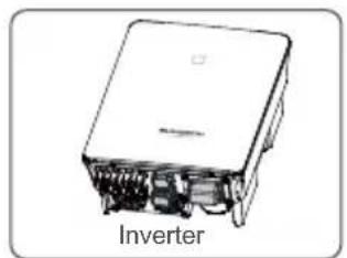
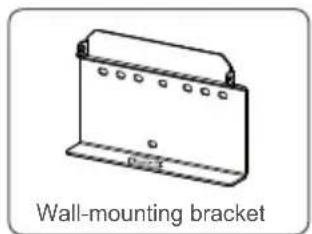
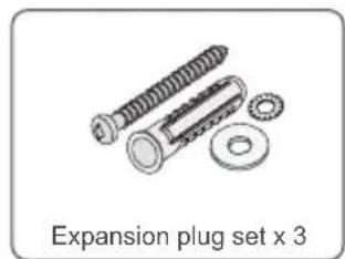
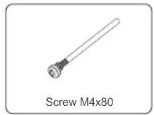
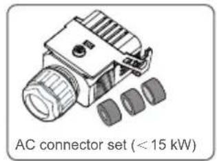
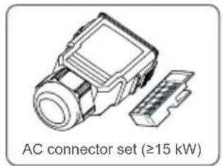
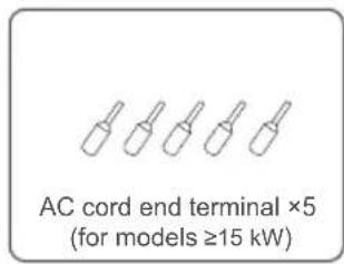
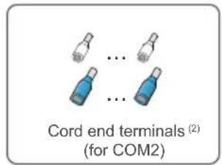
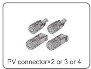
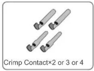
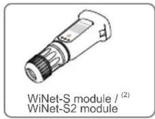
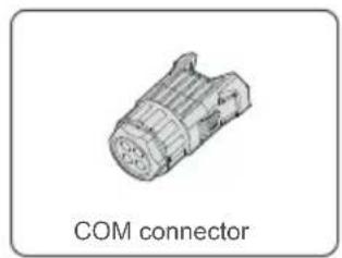
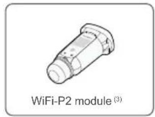
(1) The images shown here are for reference. The actual quantity is based on delivery.
(2) For countries except Brazil.
(3) For Brazil.
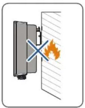
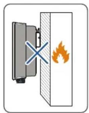
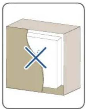
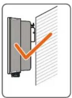
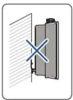
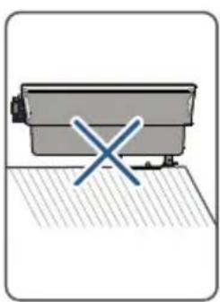
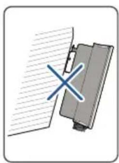
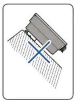
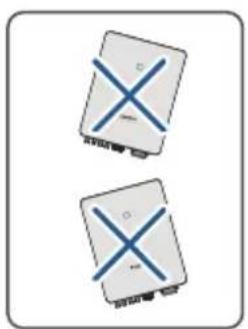
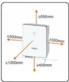
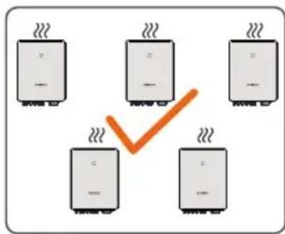
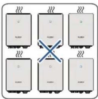
Mounting location / Montageort / Luogo di montaggio / Lieu de montage / Montagelocatie / Miejsce montazu / Monteringsplats / Asennuspaikka / Localização na parede / Local de instalação / U bicación del montaje / Lugar de montaje / Mecto yctahOBKN
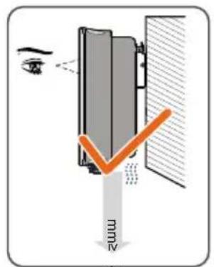
400
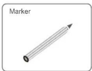
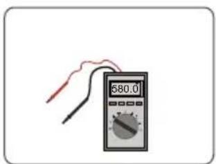
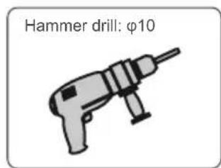
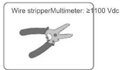
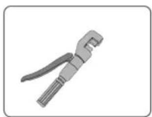
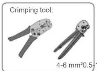
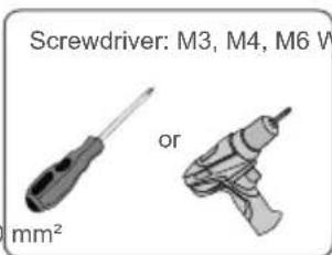
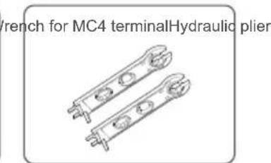
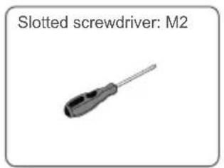
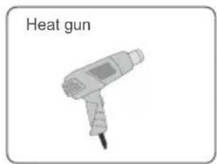
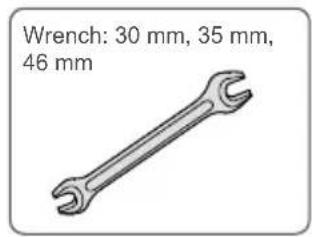
Installation tools / Werkzeug zur Installation / Strumenti di installation/ Outils d'installation / Montagegereedschap / Narzêdzia montañowe / Installationsverktyg / Asennustyōkalut / Ferramentas de instalación / Ferramentas de instalación / Herrrientas de instalación / Herrrientas para la instalación / MoHTaЖнБи ИНстpyмент

Mounting / Montage / Montaggio / Montage / Montage / Montaz / Montering / Asentaminen / Montagem / Montagem / Montaje / Montaje / MoHTax
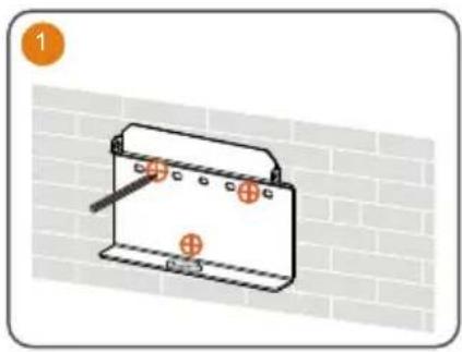
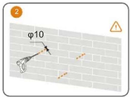
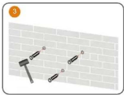
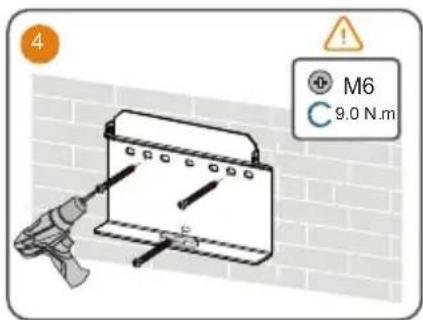
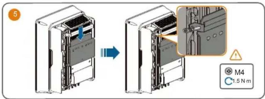
Use appropriate mounting hardware for wall type.
The image shown here is for reference only. The actual product received may differ.
Optimizer:
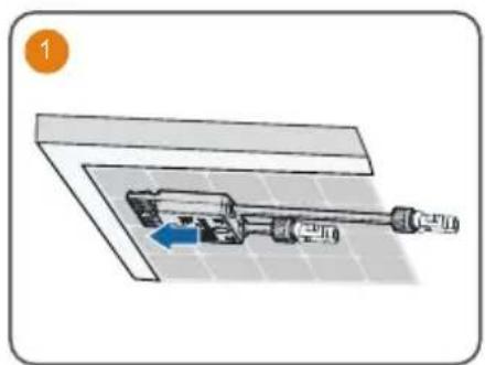
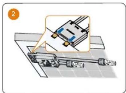
- Please ensure that the optimizer is installed facing the back of the module. Otherwise, the clip may be damaged.
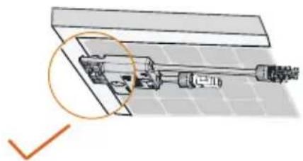
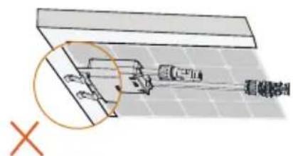
- Do not forcibly bend the clips when installing the optimizer by clips. Otherwise, the clip may be damaged.
- Do not clamp the optimizer into holes in the module frame during installation. Otherwise, the optimizer cannot be removed or the clips may be damaged.
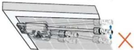
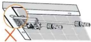
It is recommended to install optimizers on the same side of modules.
- Do not clamp and remove the optimizer multiple times. Otherwise, the clip may become loose, affecting normal use.
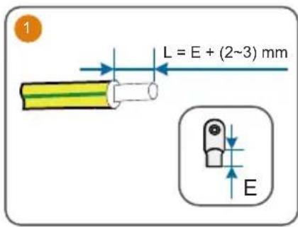
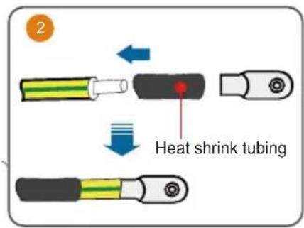
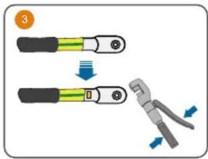
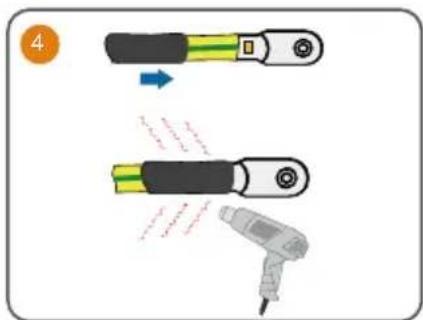
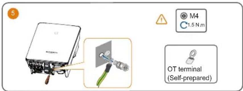
PE / Erdung / messa a terra / Mise à la terre / Aarding / PE / Skyddsjord / PE / EP / PE / PE / Energía potencial / 3aεmène
AC
It is recommended to use heavy duty conduits when run cables through Cavity walls, or lay out cables with corresponding conduits.
A RCD is not required if either of these two installation methods is adopted according to the local standard AS3000-2018. (For "AU" and "NZ")
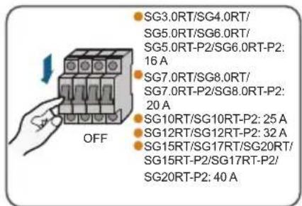
For inverter models >15kW
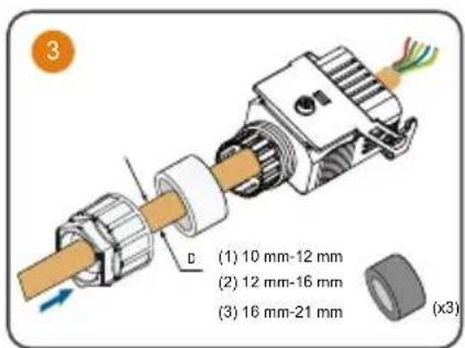
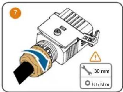
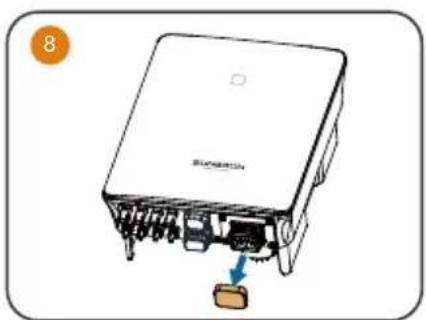
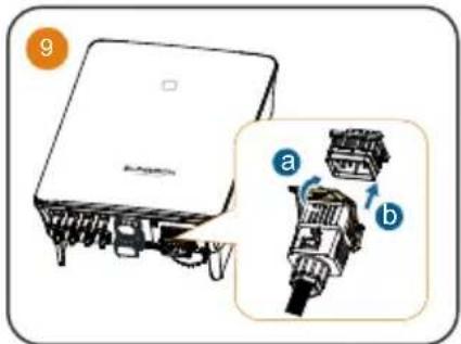
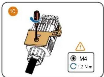
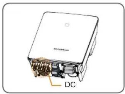
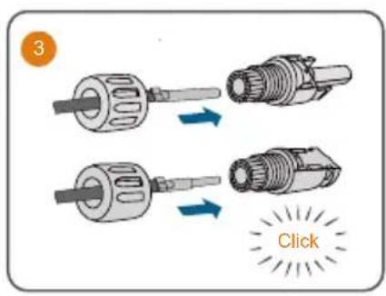
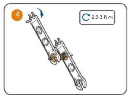
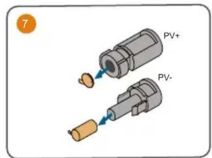
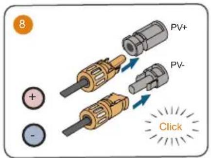
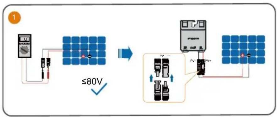
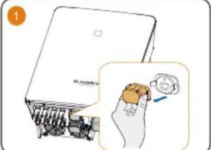
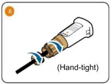
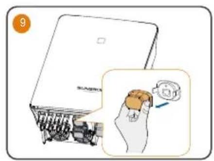
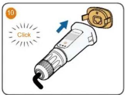
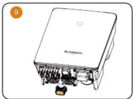
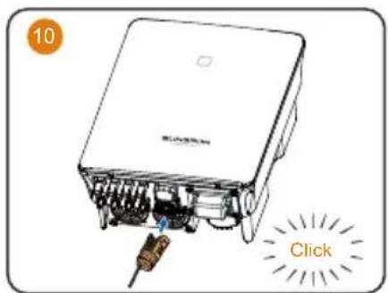
DC
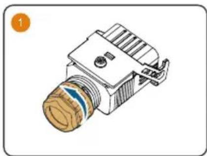
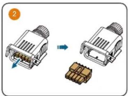
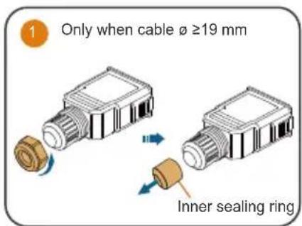
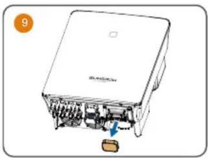
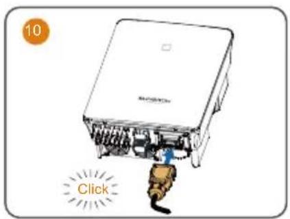
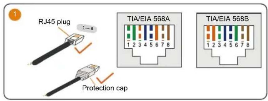
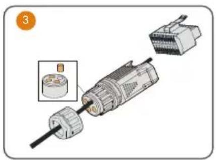
If the DC protection cover delivered separately need to be installed on site, please firstly lead the DC cables through the waterproof terminal on the DC protection cover and then assemble the DC connectors.
It is recommended to use heavy duty conduits when run cables through Cavity walls, or lay out cables with corresponding conduits.
A RCD is not required if either of these two installation methods is adopted according to the local standard AS3000-2018. (For "AU" and "NZ")
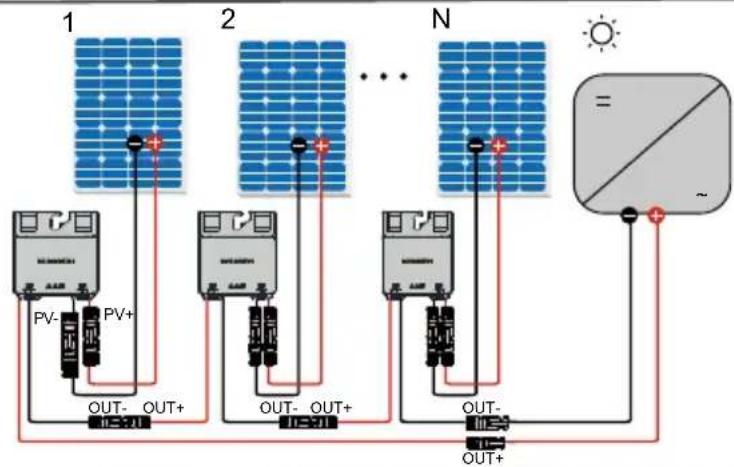
Optimizer
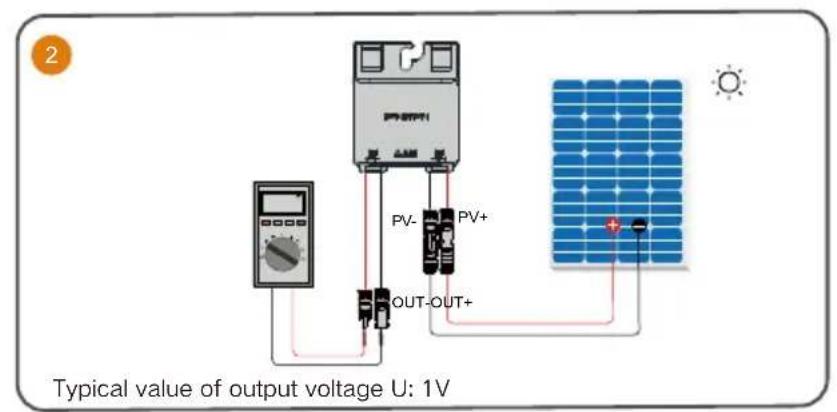

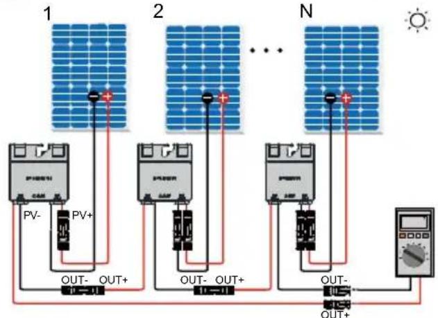
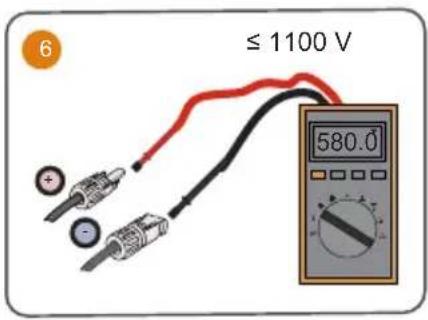
Typical value of output voltage V: 1V^*N

WLAN
Ethernet
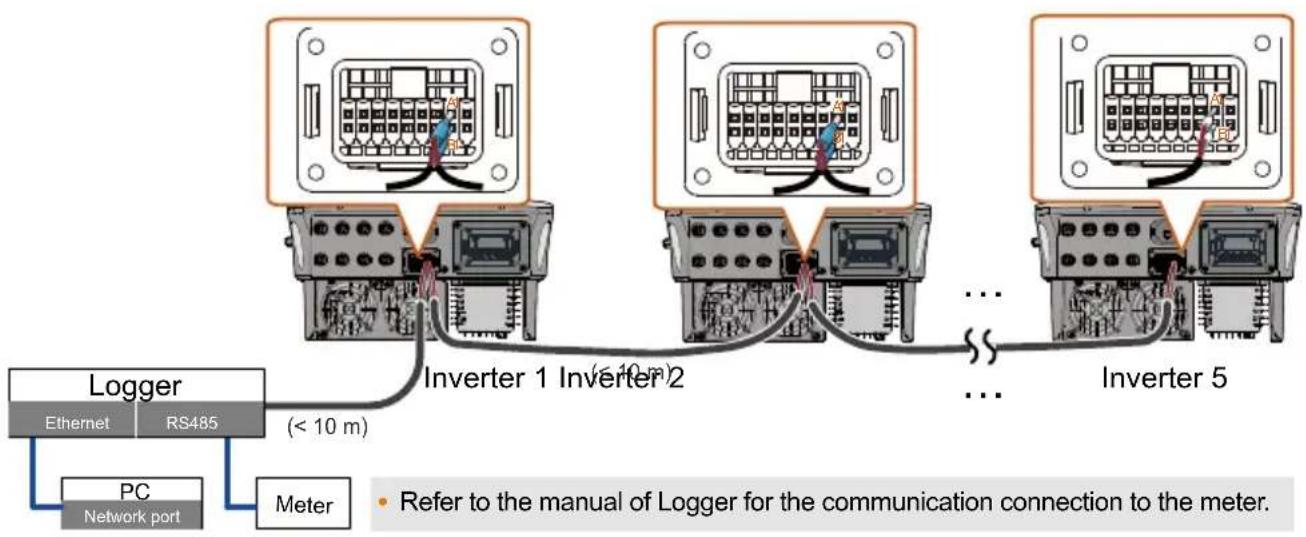
(Cannot be used simultaneously with A1 and B1 terminals for RS485 daisy chain)
COM2
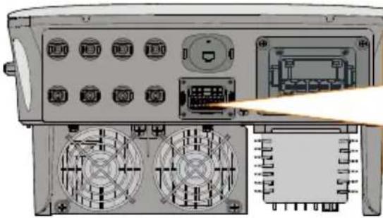
| RSD | NS | DRM | RS485-1 | DO | ||||
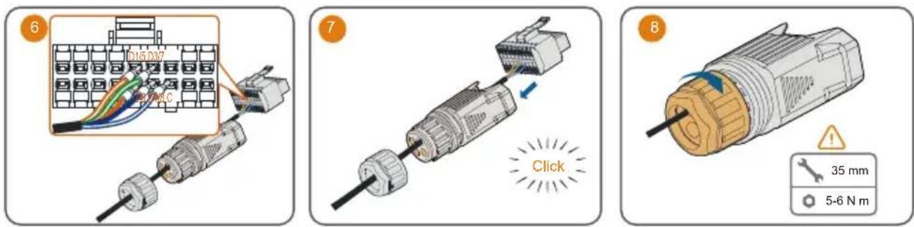
| RSD-1 | RSD-2 | NS-1 | NS-2 | D1/5 | D3/7 | R | A1 | NO |
| B3 | A3 | B2 | A2 | D2/6 | D4/8 | C | B1 | COM |
| RS485-3 | Meter | |||||||
| Label. Description | |
| RSD (RSD-1, RSD-2) For inverter emergency stop | |
| NS (NS-1, NS-2) For inverter emergency stop | |
| DRM (D1/5, D2/6, D3/7, D4/8, R, C) | For external Demand Response Enabling Device ("AU"/"NZ") For Ripple Control |
| RS485-1 (A1, B1) | For inverter daisy chain (Cannot be used simultaneously with COM1 port for WiNet-S/WiNet-S2) |
| DO (NO, COM) | External alarm interface, e.g. light indicator and/or buzzer The external DC voltage should not be higher than 30 V and the current not higher than 1 A. |
| RS485-3 (B3, A3) Reserved | |
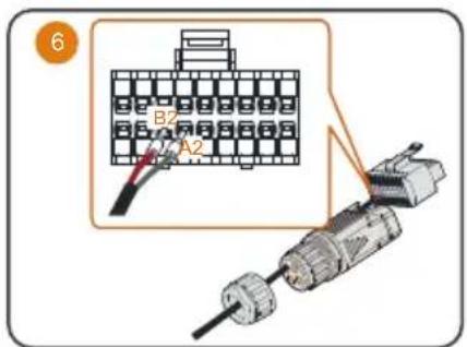
| Meter (B2, A2) | If the device is connected to iHomeManager, ensure that the corresponding Smart energy meter interface |
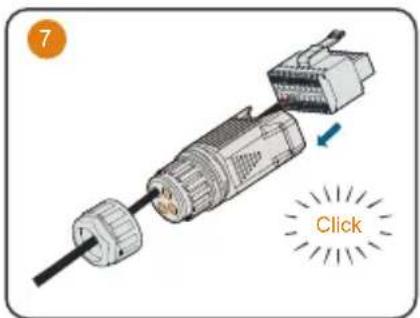
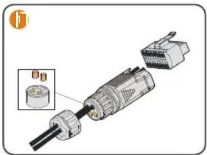
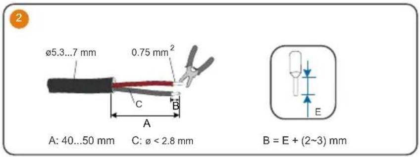
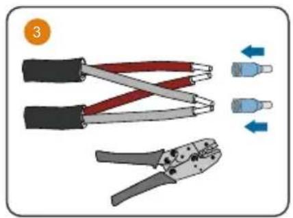
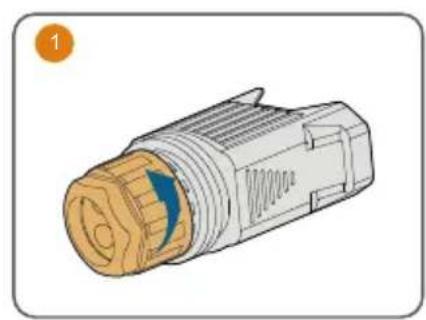
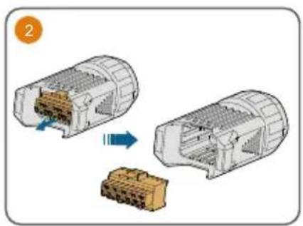
The connections for Meter (single inverter), DO, NS and DRM are the same. Take meter connection as an example.
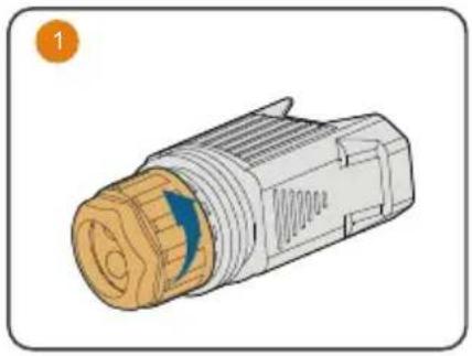
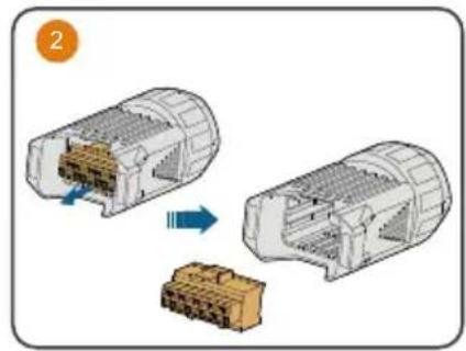
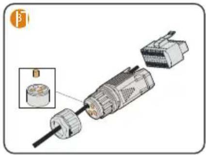
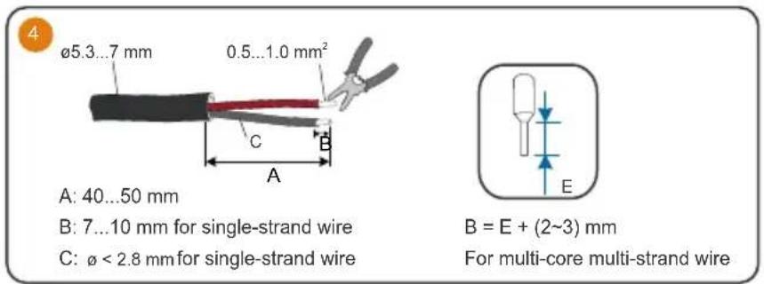
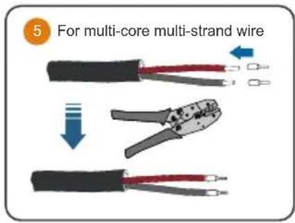
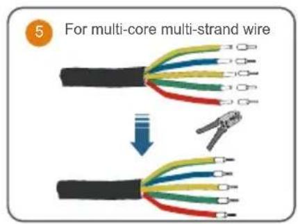
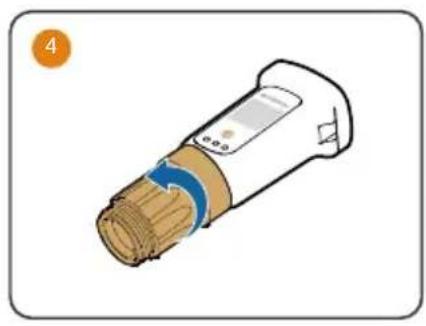
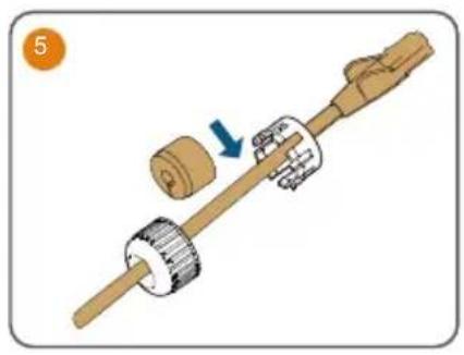
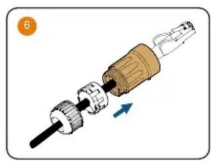
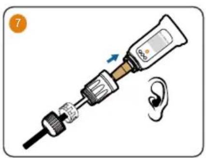
The followings describe the procedure to crimp two wires to the two-wire core end terminal. Other steps are the same as meter connection described previously.
Ripple control
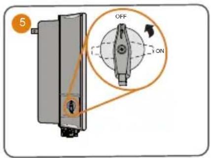
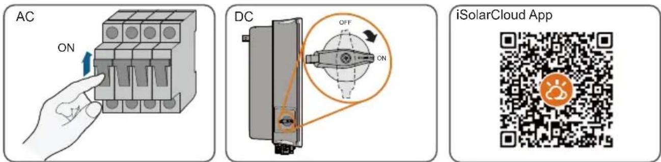
Power on / Ein / Accensione / Allumer / Schakel in / Włącznik / Effekt på / Virta kytketty / Ligação / Ligar / Encendido / Encendido / Będʒουkraine piṇṭańia
LED indicator / LED-Anzeigetafel / Indicatore LED / Voyants LED / Led-indicators / Kontrolki LED / LED-indikator / Merkkivalo / Indicador de LED / Indicador LED / Indicador LED / Indicador LED / XXK-naheb
LED indicator LED state Definition

ON The inverter is normally running.
Flashing The inverter is at standby or startup state (not feeding power into the gird).

ON A system fault has occurred.

OFF Both the AC and DC sides are powered down.

More information in the QR code or at http://support.sungrowpower.com/