SG12RT - Battery charger Sungrow - Free user manual and instructions
Find the device manual for free SG12RT Sungrow in PDF.
User questions about SG12RT Sungrow
0 question about this device. Answer the ones you know or ask your own.
Ask a new question about this device
Download the instructions for your Battery charger in PDF format for free! Find your manual SG12RT - Sungrow and take your electronic device back in hand. On this page are published all the documents necessary for the use of your device. SG12RT by Sungrow.
USER MANUAL SG12RT Sungrow
3-Phase PV Grid-Connected Inverter
Quick Installation Guide
SG3.0RT / SG4.0RT / SG5.0RT / SG6.0RT / SG7.0RT
SG8.0RT / SG10RT / SG12RT / SG15RT / SG17RT
SG20RT / SG5.0RT-P2 / SG6.0RT-P2 / SG7.0RT-P2
SG8.0RT-P2 / SG10RT-P2 / SG12RT-P2 / SG15RT-P2
SG17RT-P2 / SG20RT-P2
natural_image
White SunGROW device with a small blue square logo and 'SUNGROW' branding on its body (no additional text or symbols visible)EN
- The Contents may be periodically updated or revised due to product development. The information in this guide is subject to change without notice. In no case shall this guide substitute for the user manual or related notes on the device.
- Make sure to read over, fully understand and strictly follow the detailed instructions of the user manual and other related regulations before installing the equipment. The user manual can be downloaded by visiting the website at http://support.sungrowpower.com/; or it can be obtained by scanning the QR code on the side of the equipment or the back cover of this guide.
- All installations must be performed by qualified personnel who should have training for installation and commissioning of electrical system, as well as dealing with hazards, have knowledge of the manual and of the local regulations and directives.
- Before installation, check that the package contents are intact and complete compared to the packing list. Contact SUNGROW or the distributor in case of any damaged or missing components.
- The cable used must be intact and well insulated. Operation personnel must wear proper personal protective equipment (PPE) all the time.
- Any violation could result in personal death or injury or device damage, and will void the warranty.
Safety
The inverter has been designed and tested strictly according to international safety regulations. Read all safety instructions carefully prior to any work and observe them at all times when working on or with the inverter. Incorrect operation or work may cause:
- injury or death to the operator or a third party;
• damage to the inverter and other properties.
Please follow the safety instructions related to the PV strings and the utility grid.

DANGER
Lethal voltage!
- PV strings will produce electrical power when exposed to sunlight and can cause a lethal voltage and an electric shock.
- Only qualified personnel can perform the wiring of the PV panels.

NOTICE
Danger to life from electric shock due to lethal voltage!
- All electrical connections must be in accordance with local and national standards.
- Only with the permission of the utility grid, the inverter can be connected to the utility grid.
Inverter
The icons on the inverter body are as follows.

Disconnect the inverter from all the external power sources before maintenance!
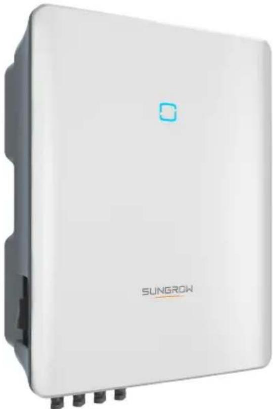
Burn danger due to hot surface that may exceed 60 °C .

Read the user manual before maintenance!
RCM mark of conformity.
 | Danger to life due to high voltages!Only qualified personnel can open and maintain the inverter. |  |  10 min 10 min | Danger to life due to high voltages!Do not touch live parts for 10 minutes after disconnection from the power sources.Only qualified personnel can open and service the inverter. |
| TÜV mark of conformity. | CE | CE mark of conformity.EU/EEA Importer. | ||
 | Do not dispose of the inverter together with household waste. |  | The inverter does not have a transformer. | |
 | Additional grounding point. UKCA mark of con  | |||
 | RoHS labelingThe product complies with the requirements of the applicable EU directives. |  | CMIM-Prüfzeichen. | |
Users may also attach other warning signs as per the requirements of the local standards or installation specifications.
Security Declaration
- For details on the product's network security vulnerability response process and vulnerability disclosure, please scan the QR code on the right or visit the following website: https://en.sungrowpower.com/security-vulnerability-management
- For more information on network security, please refer to the user manual of the communication module or the Data Logger that comes with the product.

EU Declaration of Conformity
within the scope of the EU directives:
• Low Voltage Directive 2014/35/EU (LVD)
• Electromagnetic compatibility Directive 2014/30/EU (EMC)
• Restriction of the use of certain hazardous substances 2011/65/EU and 2015/863/EU (RoHS)
The manufacturer Sungrow Power Supply Co., Ltd, China hereby confirms that the product SG3.0-20RT&SG5.0-20RT-P2 complies with the essential requirements and other relevant provisions of Directives 2014/35/EU, 2014/30/EU, 2011/65/EU, 2015/863/EU. The full EU Declaration of Conformity can be found at https://support.sungrowpower.com/PdfDetail?id=1697881433535078402.
- The communication module that comes with the inverter and the technical parameters of wireless communication are listed in the table below. The model of the communication module actually delivered shall prevail. The EU Declaration of Conformity for the communication module can be found at support.sungrowpower.com.


WiNet-S/WiNet-S2:
Technologie radio WLANI 802.11b/g/n20/n40
| Radio spectrum | 802.11b/g/n | 2412 MHz ~ 2472 MHz |
| 802.11n40 | 2422 MHz ~ 2462 MHz |
Maximum transmitted power ≤ 20 dBm
Technical parameters listed above apply to EU countries only.
Manufacturer:
Sungrow Power Supply Co., Ltd.
No 1699. Xiyou Road, Hefei 230088. P.R China
For EU only
EU/EEA Importer:
Danger to life from electric shocks due to live voltage
- Do not open the enclosure at any time. Unauthorized opening will void warranty and warranty claims and in most cases terminate the operating license.
- When the enclosure lid is removed, live components can be touched which can result in death or serious injury due to electric shock.
Lethal danger from electric shock due to possibly damaged inverter
- Only operate the inverter when it is technically faultless and in a safe state.
- Operating a damaged inverter can lead to hazardous situations that can result in death or serious injuries due to electric shock.

WARNING
Risk of inverter damage or personal injury
- Do not connect or disconnect the PV and AC connectors when the inverter is running.
- Wait at least 10 minutes for the internal capacitors to discharge after all electric devices are removed and the inverter is powered off.
- Ensure that there is no voltage or current before connecting or disconnecting the PV and AC connectors.

WARNING
All the warning labels and nameplate on the inverter body:
- must be clearly visible; and
- must not be removed, covered or pasted.

CAUTION
Risk of burns due to hot components!
- Do not touch any hot parts (such as the heat sinks) during operation. Only the DC switch can safely be touched at any time.

NOTICE
Only qualified personnel can perform the country setting. Unauthorized alteration may cause a breach of the type-certificate marking.
Risk of inverter damage due to electrostatic discharge (ESD)!
By touching the electronic components, you may damage the inverter. For inverter handling, be sure to:
- avoid any unnecessary touching; and
- wear a grounding wristband before touching any connectors.
DE
Sungrow Power Supply Co., Ltd.
Nr. 1699. Xiyou Road, Hefei 230088. P.R. China
Nur für die EU
Sungrow Power Supply Co., Ltd.
No 1699. Xiyou Road, Hefei 230088. R. P. Cinese
Solo per l'UE
Importatore UE/SEE: Sungrow Deutschland GmbH
Sungrow Power Supply Co., Ltd.
No 1699. Xiyou Road, Hefei 230088. P.R. China
Sungrow Power Supply Co., Ltd.
No 1699. Xiyou Road, Hefei 230088. P.R. China
Alleen voor de EU
Sungrow Power Supply Co., Ltd.
No 1699. Xiyou Road, Hefei 230088. ChRL
Tylko na eksport do UE
Users may also attach other warning signs as per the requirements of the local standards or installation specifications.
Security Declaration
For details on the product's network security vulnerability response process and vulnerability disclosure, please scan the QR code on the right or visit the following website: https://en.sungrowpower.com/security-vulnerability-management
- For more information on network security, please refer to the user manual of the communication module or the Data Logger that comes with the product.

• PV strings will produce electrical power when exposed to sunlight and can cause a lethal voltage and an electric shock.
- Only qualified personnel can perform the wiring of the PV panels.

ADVERTÊNCIA
Maximum transmitted power ≤ 20 dBm
Technical parameters listed above apply to EU countries only.
Fabricante:
Sungrow Power Supply Co., Ltd.
No 1699. Xiyou Road, Hefei 230088.P.R.China
Apenas para a UE
Importador UE/EEE: Sungrow Deutschland GmbH
Balanstraße 59, 81541 München, Alemanha

PERIGO
Sungrow Power Supply Co., Ltd.
No 1699. Xiyou Road, Hefei 230088. P.R. China
Sólo para la UE
Importador UE/EEE: Sungrow Deutschland GmbH
Balanstraße 59, 81541 München, Alemania

PELIGRO
Read the user manual before maintenance!
natural_image
Illustration of an inverter device with labeled components (no text or symbols on the device itself)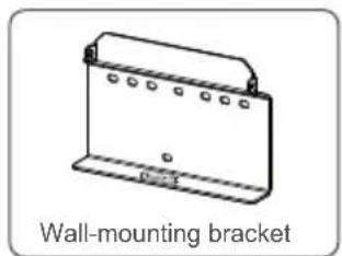
natural_image
Technical line drawing of a wall-mounted bracket with mounting holes and mounting points (no text or symbols)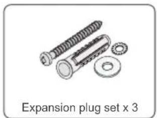
natural_image
Illustration of a mechanical assembly with bolts and a washer, labeled 'Expansion plug set x 3' (no other text or symbols)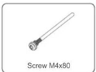
natural_image
Simple line drawing of a screw with a cylindrical shaft (no text or symbols on the object itself)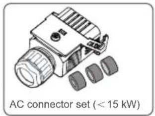
text_image
AC connector set (< 15 kW)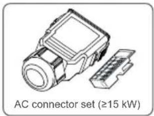
text_image
AC connector set (≥15 kW)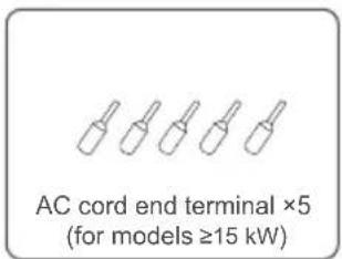
text_image
AC cord end terminal ×5 (for models ≥15 kW)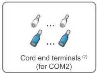
text_image
Cord end terminals (2) (for COM2)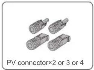
natural_image
Four identical cylindrical electronic connectors with no text or symbols on the connectors themselves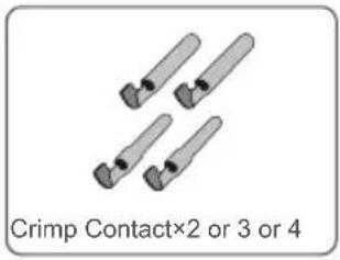
text_image
Crimp Contact×2 or 3 or 4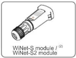
text_image
WiNet-S module / (2) WiNet-S2 module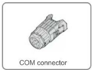
natural_image
Technical illustration of a COM connector (no text or symbols on the diagram itself)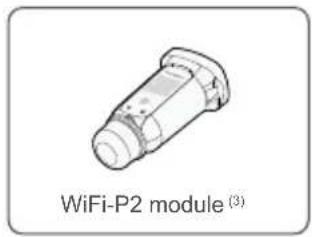
text_image
WiFi-P2 module (3)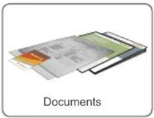
natural_image
Illustration of a layered document structure with no visible text or symbols(1) The images shown here are for reference. The actual quantity is based on delivery.
(2) For countries except Brazil.
(3) For Brazil.
Mounting location / Montageort / Luogo di montaggio / Lieu de montage / Montagelocatie / Miejsce montażu / Monteringsplats / Asennuspaikka / Localização na parede / Local de instalação / Ubicación del montaje / Lugar de montaje / Mecto установki
text_image
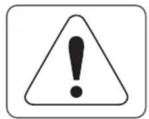
Warning symbol with exclamation mark inside a triangle, enclosed in a rounded square border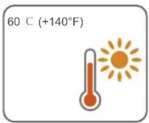
text_image
60 C (+140°F)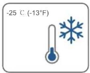
text_image
-25 ℃ (-13°F)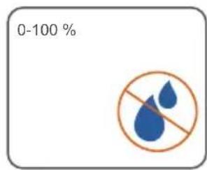
text_image
0-100 %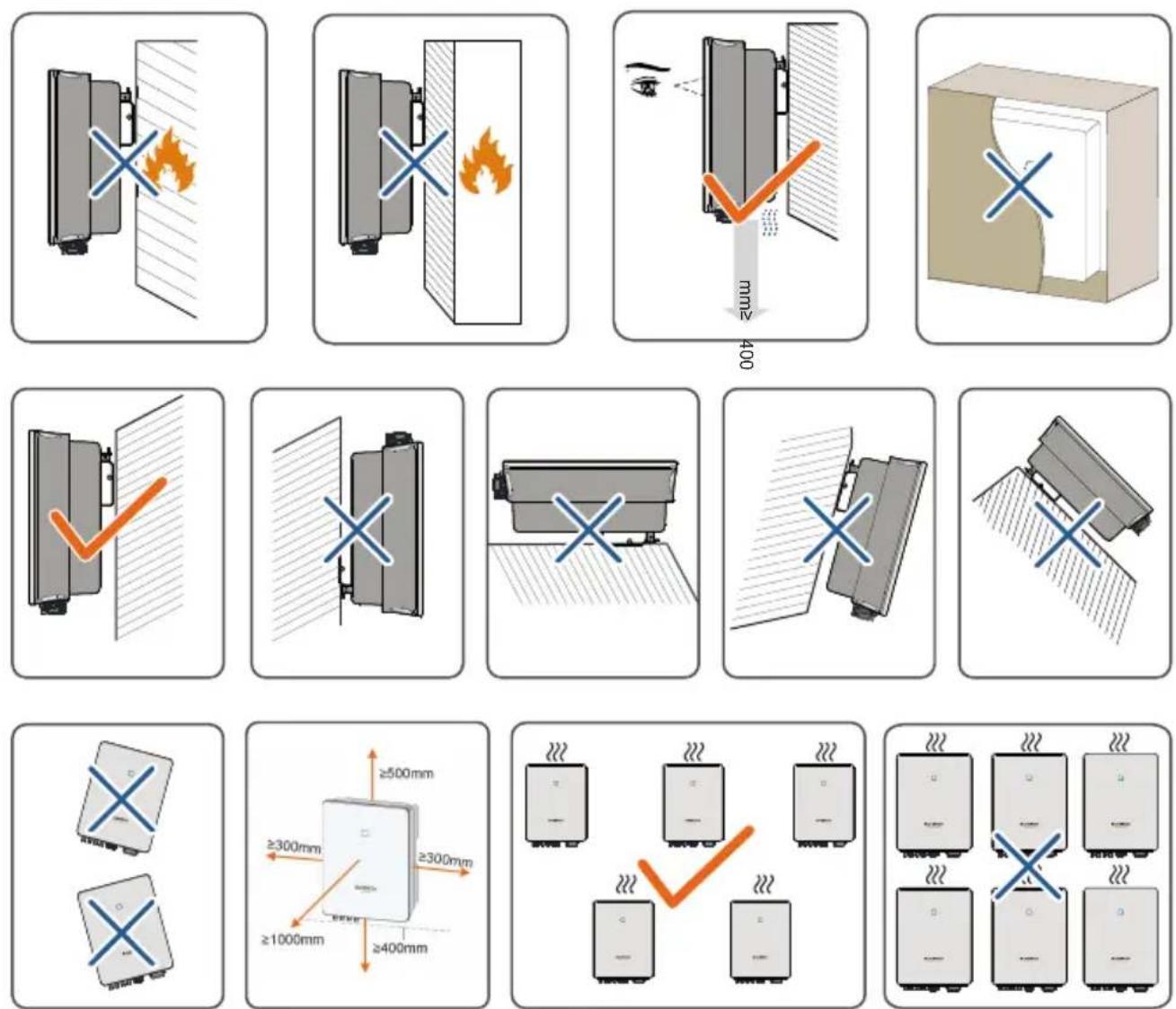
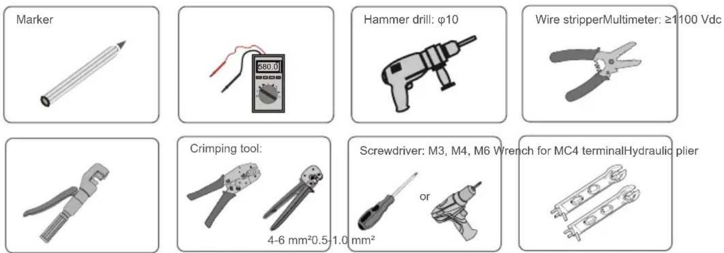
Installation tools / Werkzeug zur Installation / Strumenti di installazione/ Outils d'installation / Montagegereedschap / Narzędzia montażowe / Installationsverktyg / Asennustyökalut / Ferramentas de instalação / Ferramentas de instalação / Herramientas de instalación / Herramientas para la instalación / Монтажный инструмент
text_image
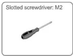
Slotted screwdriver: M2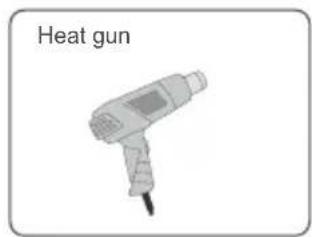
text_image
Heat gun
text_image
RJ45 Crimping tool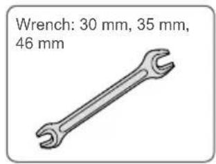
text_image
Wrench: 30 mm, 35 mm, 46 mmMounting / Montage / Montaggio / Montage / Montage / Montaz / Montering / Asentaminen / Montagem / Montagem / Montaje / Montaje / Монтаж
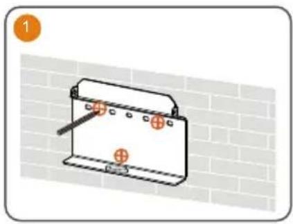
natural_image
Diagram of a battery pack with two orange test probes and a handle, set against a brick wall background (no text or symbols)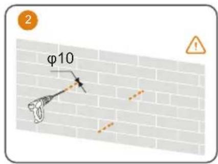
text_image
φ10 2 !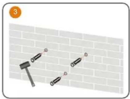
natural_image
Illustration of a hammer and two bolts on a brick wall, no text or symbols present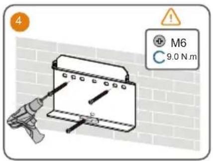
text_image
4 M6 9.0 N.m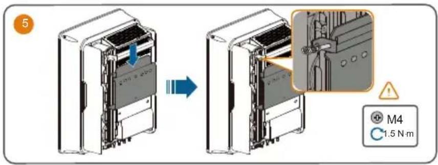
text_image
5 M4 1.5 N·mUse appropriate mounting hardware for wall type.
The image shown here is for reference only. The actual product received may differ.
Optimizer:
natural_image
Diagram of a mechanical device inside a solar panel, showing internal components and no text or symbols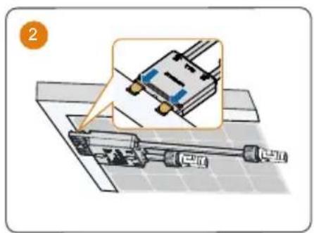
natural_image
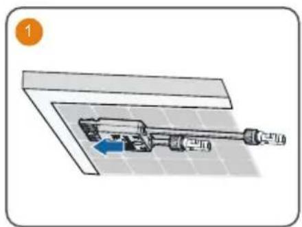
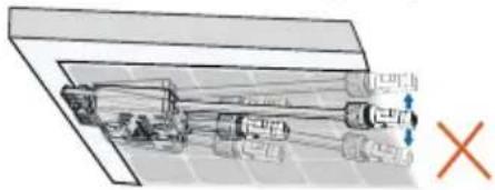
Diagram of a mechanical assembly with a magnified inset showing a component being inserted into a housing (no text or symbols present)- Please ensure that the optimizer is installed facing the back of the module. Otherwise, the clip may be damaged.
natural_image
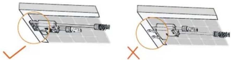
Technical illustration of a mechanical assembly with cross-sectional views (no text or symbols)- Do not forcibly bend the clips when installing the optimizer by clips. Otherwise, the clip may be damaged.
- Do not clamp the optimizer into holes in the module frame during installation. Otherwise, the optimizer cannot be removed or the clips may be damaged.
natural_image
Mechanical assembly diagram showing internal components and a red X mark (no text or labels)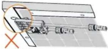
natural_image
Diagram of a mechanical assembly with a magnified inset showing internal components (no text or labels)- It is recommended to install optimizers on the same side of modules.
- Do not clamp and remove the optimizer multiple times. Otherwise, the clip may become loose, affecting normal use.
PE / Erdung / messa a terra / Mise à la terre / Aarding / PE / Skyddsjord / PE / EP / PE / PE / Energía potencial / Заземление
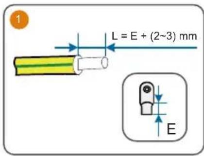
text_image
L = E + (2~3) mm E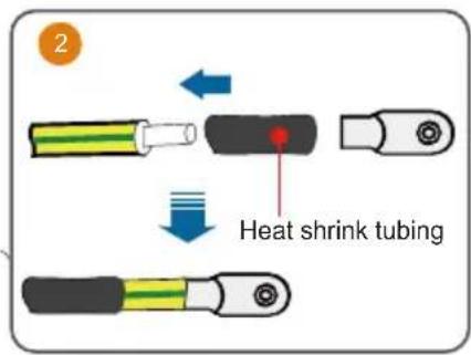
text_image
2 Heat shrink tubing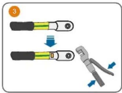
text_image
Diagram illustrating a cable clamp operation with labeled parts and directional arrows indicating movement.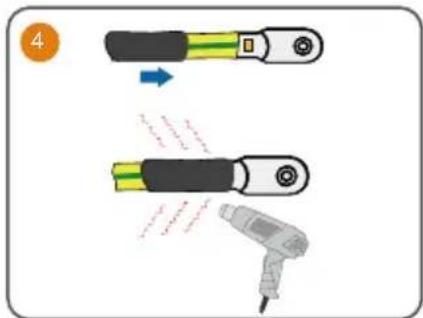
text_image
Diagram illustrating a cable or connector being inserted into a plug, with Chinese text indicating the process.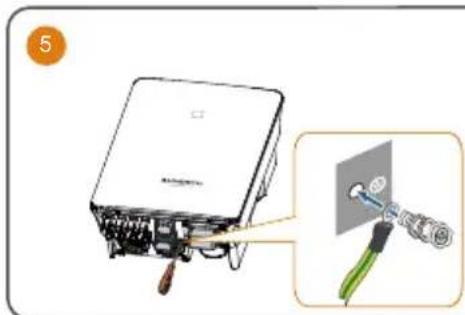
text_image
5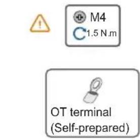
text_image
M4 1.5 N.m OT terminal (Self-prepared)AC
It is recommended to use heavy duty conduits when run cables through Cavity walls, or lay out cables with corresponding conduits.
A RCD is not required if either of these two installation methods is adopted according to the local standard AS3000-2018. (For "AU" and "NZ")
text_image
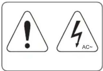
! AC~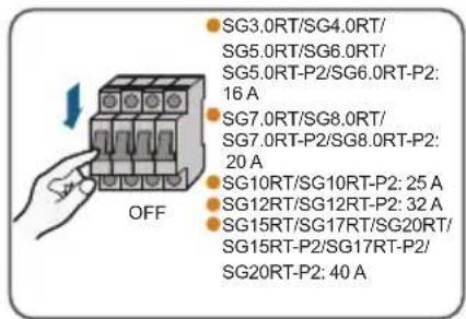
text_image
OFF • SG3.0RT/SG4.0RT/ SG5.0RT/SG6.0RT/ SG5.0RT-P2/SG6.0RT-P2: 16 A • SG7.0RT/SG8.0RT/ SG7.0RT-P2/SG8.0RT-P2: 20 A • SG10RT/SG10RT-P2: 25 A • SG12RT/SG12RT-P2: 32 A • SG15RT/SG17RT/SG20RT/ SG15RT-P2/SG17RT-P2/ SG20RT-P2: 40 A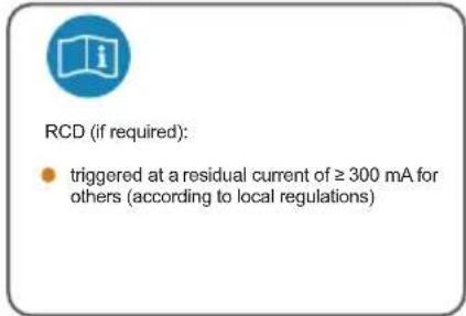
text_image
RCD (if required): • triggered at a residual current of ≥ 300 mA for others (according to local regulations)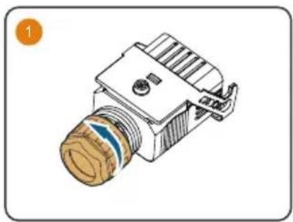
natural_image
Technical illustration of a mechanical component with threaded shaft and mounting bracket (no text or symbols)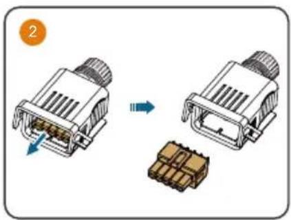
natural_image
Diagram showing two connected electrical connectors with a close-up view of the connector (no text or symbols present)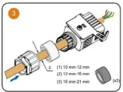
text_image
(1) 10 mm-12 mm (2) 12 mm-16 mm (3) 16 mm-21 mm (x3)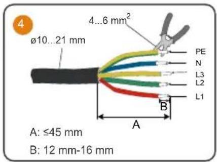
text_image
4 ø10...21 mm 4...6 mm² PE N L3 L2 L1 A B A: ≤45 mm B: 12 mm-16 mm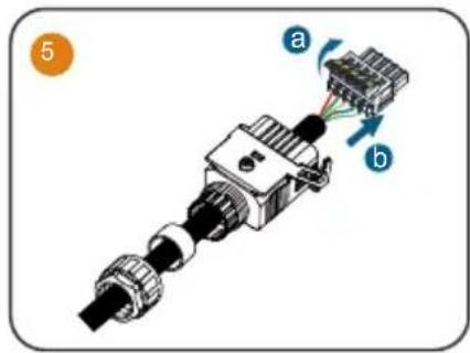
text_image
5 a b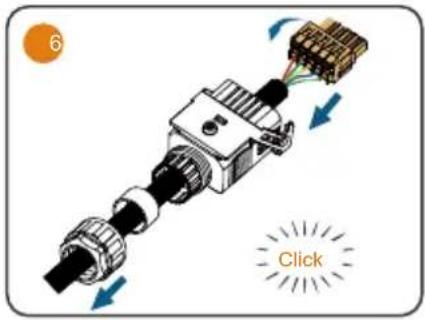
text_image
6 Click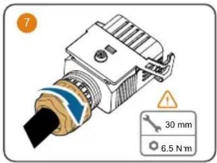
text_image
7 30 mm 6.5 N m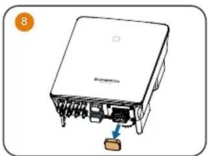
natural_image
Illustration of an electronic device with a labeled component and arrow indicating connection (no text or symbols present)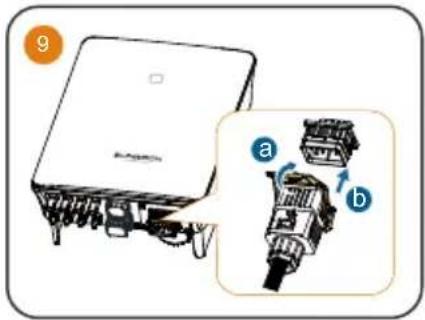
text_image
9 a b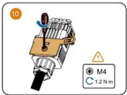
text_image
10 M4 1.2 N mFor inverter models > 15 kW
text_image
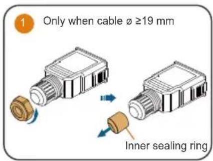
Only when cable ø ≥19 mm Inner sealing ring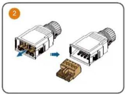
natural_image
Diagram showing two connected electrical connectors with internal components, one being rotated and the other assembled (no text or symbols present)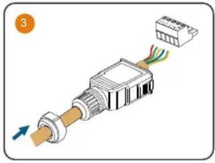
natural_image
Diagram of an electrical connector with color-coded wires and a terminal block, no text or symbols present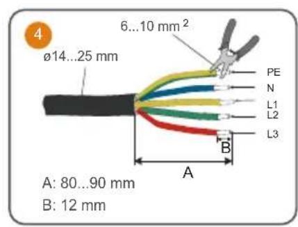
text_image
4 ø14...25 mm 6...10 mm² PE N L1 L2 L3 A B A: 80...90 mm B: 12 mm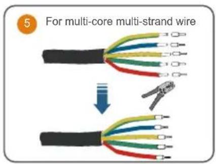
text_image
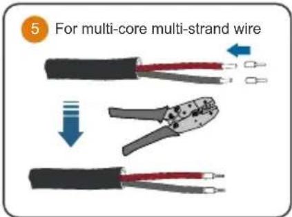
5 For multi-core multi-strand wire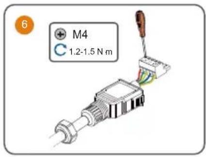
text_image
6 M4 C 1.2-1.5 N m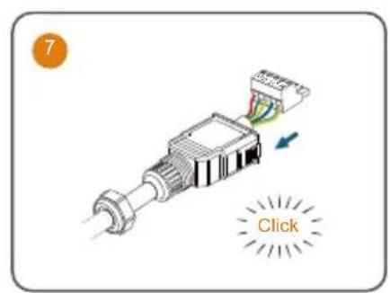
text_image
7 Click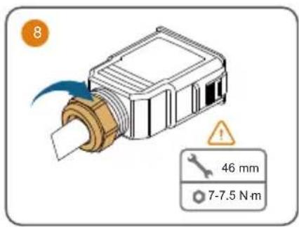
text_image
8 46 mm 7-7.5 N·m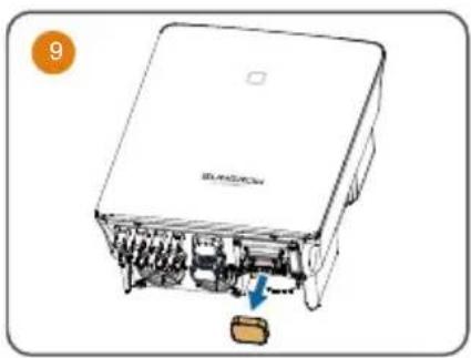
natural_image
Diagram of a device with internal components and a blue arrow indicating a specific area (no text or symbols present)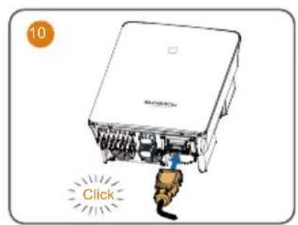
text_image
10 Click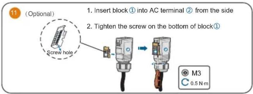
text_image
11 (Optional) 1. Insert block ① into AC terminal ② from the side 2. Tighten the screw on the bottom of block① Screw hole M3 0.5 N mDC
If the DC protection cover delivered separately need to be installed on site, please firstly lead the DC cables through the waterproof terminal on the DC protection cover and then assemble the DC connectors.
It is recommended to use heavy duty conduits when run cables through Cavity walls, or lay out cables with corresponding conduits.
A RCD is not required if either of these two installation methods is adopted according to the local standard AS3000-2018. (For "AU" and "NZ")
text_image
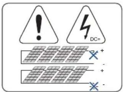
! DC= + - + -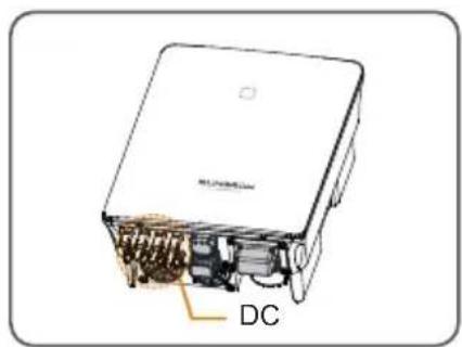
text_image
DC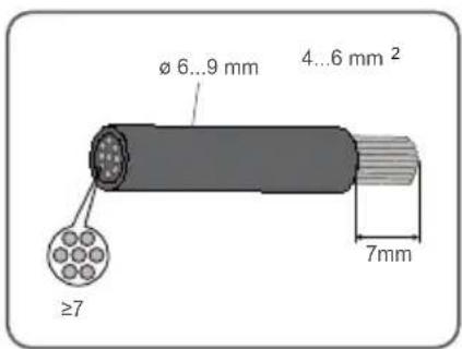
text_image
Ø 6...9 mm 4...6 mm² ≥7 7mm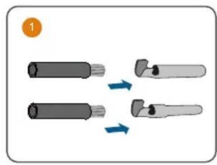
natural_image
Diagram showing two cylindrical objects with arrows indicating transformation or assembly (no text or symbols)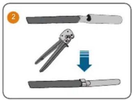
natural_image
Illustration of a pair of crimping scissors with a downward arrow indicating compression (no text or symbols)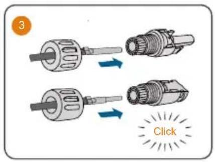
text_image
3 Click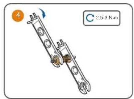
text_image
4 C 2.5-3 N·m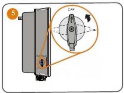
text_image
OFF ON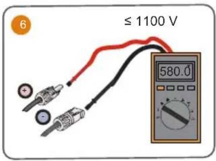
text_image
6 ≤ 1100 V 580.0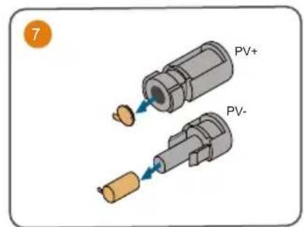
text_image
7 PV+ PV-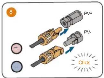
text_image
8 PV+ PV- ClickOptimizer
text_image
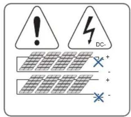
DC- + - + -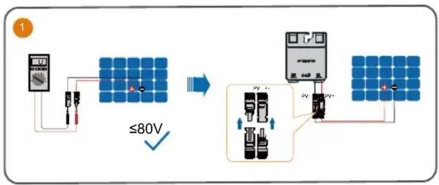
text_image
1 ≤80V PV +- PV PV+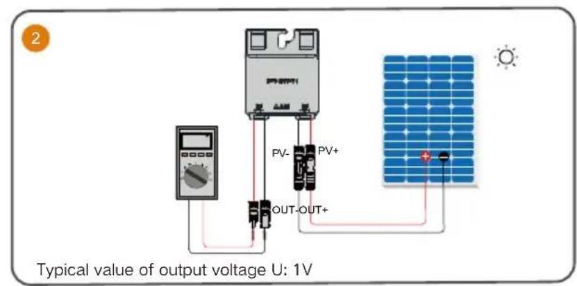
text_image
Typical value of output voltage U: 1V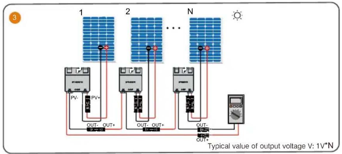
text_image
1 2 N PV- PV+ OUT- OUT+ OUT- OUT+ OUT- OUT+ Typical value of output voltage V: 1V*N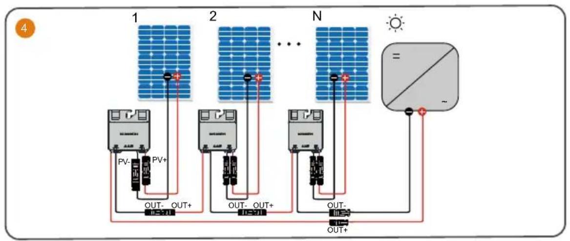
flowchart
graph TD
    A["Panel 1: Solar Panel"] --> B["PV-"]
    A --> C["PV+"]
    B --> D["OUT- OUT+"]
    C --> E["OUT- OUT+"]
    D --> F["Panel 2: Solar Panel"]
    E --> G["Panel 2: Solar Panel"]
    F --> H["..."]
    G --> I["..."]
    H --> J["N: Solar Panel"]
    I --> K["N: Solar Panel"]
    J --> L["Out- OUT+"]
    K --> M["Out- OUT+"]
    L --> N["Output Symbol"]
    M --> O["Output Symbol"]
WLAN
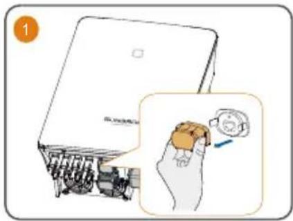
text_image
1 2014/06/23 2014/06/23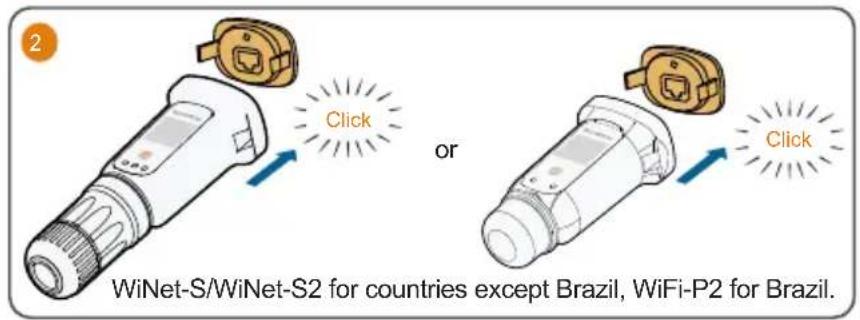
text_image
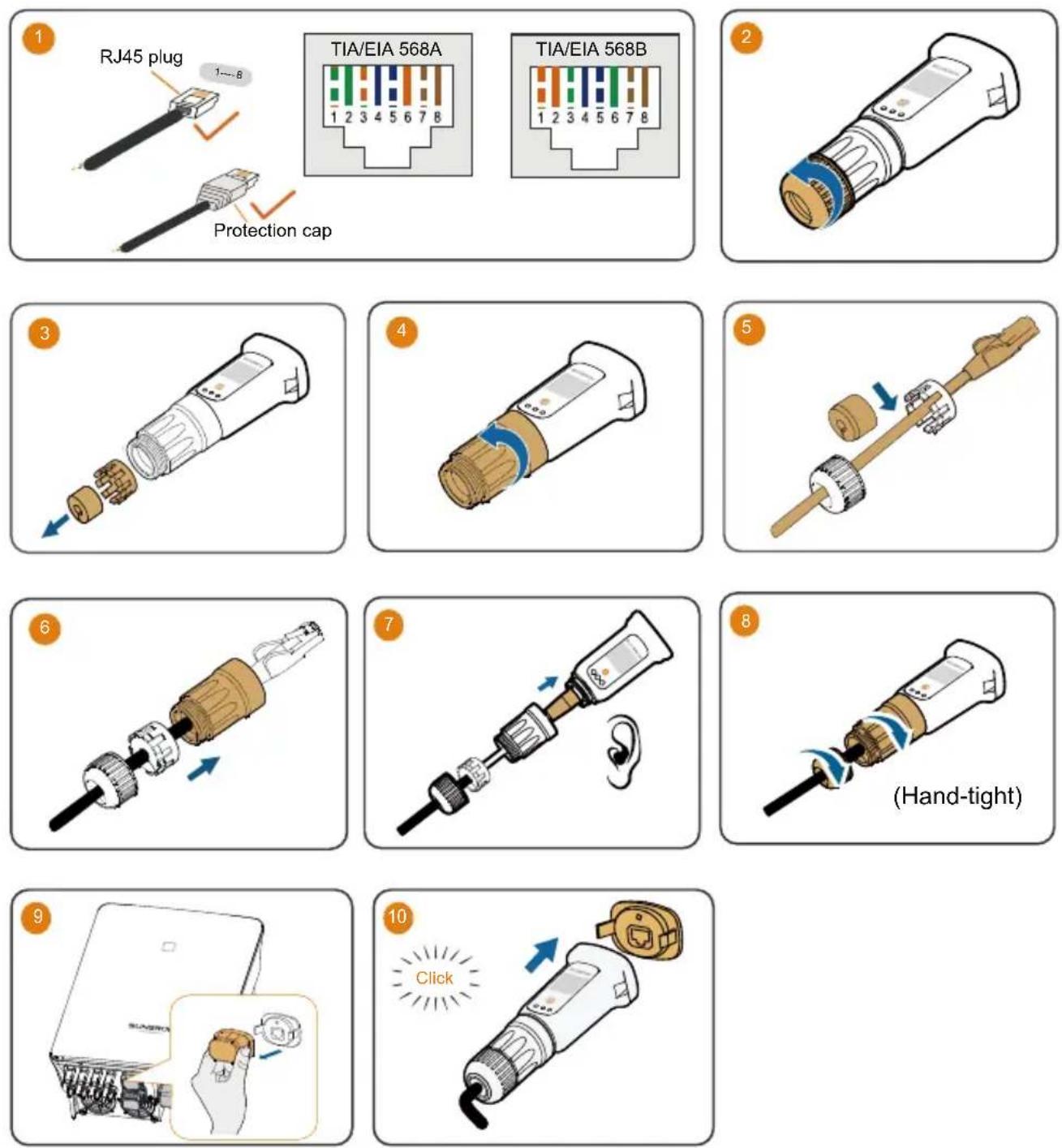
2 Click or Click WiNet-S/WiNet-S2 for countries except Brazil, WiFi-P2 for Brazil.Ethernet
(Cannot be used simultaneously with A1 and B1 terminals for RS485 daisy chain)
COM2
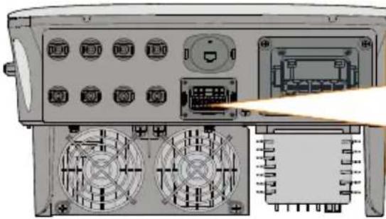
natural_image
Back view of a computer control panel with labeled buttons and connectors (no readable text or symbols)| RSD | NS | DRM | RS485-1 | DO | ||||
| RSD-1 | RSD-2 | NS-1 | NS-2 | D1/5 | D3/7 | R | A1 | NO |
| B3 | A3 | B2 | A2 | D2/6 | D4/8 | C | B1 | COM |
| RS485-3 | Meter | |||||||
| Label. Description | |
| RSD (RSD-1, RSD-2) For inverter emergency stop | |
| NS (NS-1, NS-2) For inverter emergency stop | |
| DRM (D1/5, D2/6, D3/7, D4/8, R, C) | For external Demand Response Enabling Device ("AU"/"NZ")For Ripple Control |
| RS485-1 (A1, B1) | For inverter daisy chain(Cannot be used simultaneously with COM1 port for WiNet-S/WiNet-S2) |
| DO (NO, COM) | External alarm interface, e.g. light indicator and/or buzzerThe external DC voltage should not be higher than 30 V and the current not higher than 1 A. |
| RS485-3 (B3, A3) Reserved | |
| Meter (B2, A2) | If the device is connected to iHomeManager, ensure that the corresponding Smart energy meter interface |
• The connections for Meter (single inverter), DO, NS and DRM are the same. Take meter connection as an example.
natural_image
Illustration of a mechanical connector with threaded body and orange internal component (no text or symbols)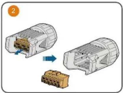
natural_image
Diagram showing two views of a connector housing with internal components, one being cut and the other assembled (no text or symbols)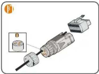
natural_image
Exploded view diagram of a mechanical component with internal parts and an inset showing a cylindrical component (no text or symbols)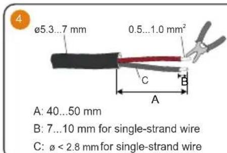
text_image
4 ø5.3...7 mm 0.5...1.0 mm² A: 40...50 mm B: 7...10 mm for single-strand wire C: ø < 2.8 mm for single-strand wire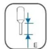
B = E + (2\~3) mm
For multi-core multi-strand wire
text_image
5 For multi-core multi-strand wire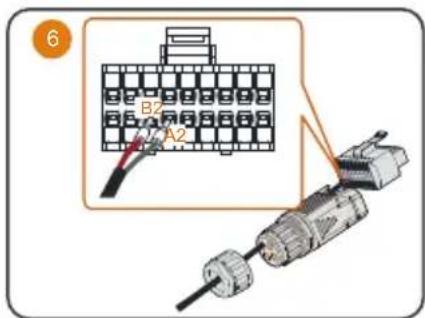
text_image
6 B2 A2 A1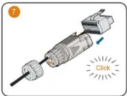
text_image
7 Click
text_image
8 35 mm 5-6 N m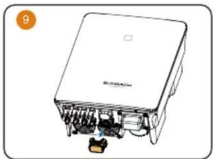
natural_image
Illustration of a device with internal components and a label '9' in the corner (no readable text or symbols on the device itself)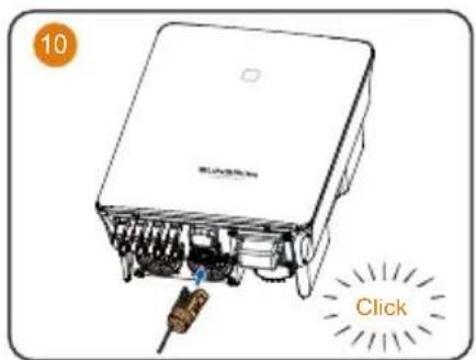
text_image
10 ClickInverter RS485 Daisy Chain (≤ 5)
The followings describe the procedure to crimp two wires to the two-wire core end terminal. Other steps are the same as meter connection described previously.
natural_image
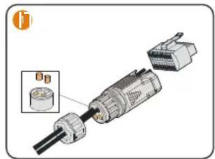
Exploded view diagram of a mechanical component with internal parts and an inset showing a cylindrical component (no text or symbols)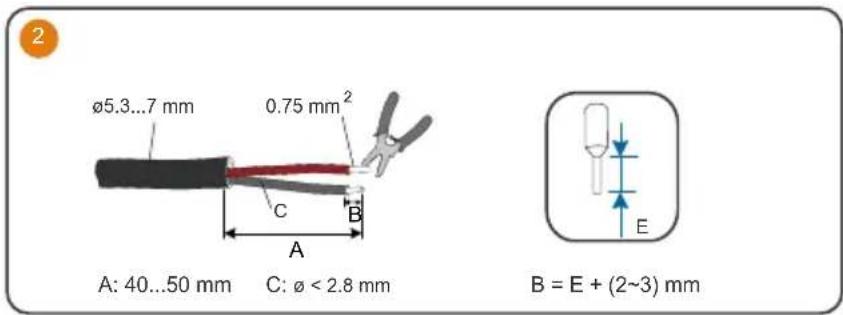
text_image
Ø5.3...7 mm 0.75 mm² A: 40...50 mm C: Ø < 2.8 mm B = E + (2~3) mm
text_image
Diagram showing two types of pliers with red and gray wires, connected to blue connectors, with arrows indicating connection or movement.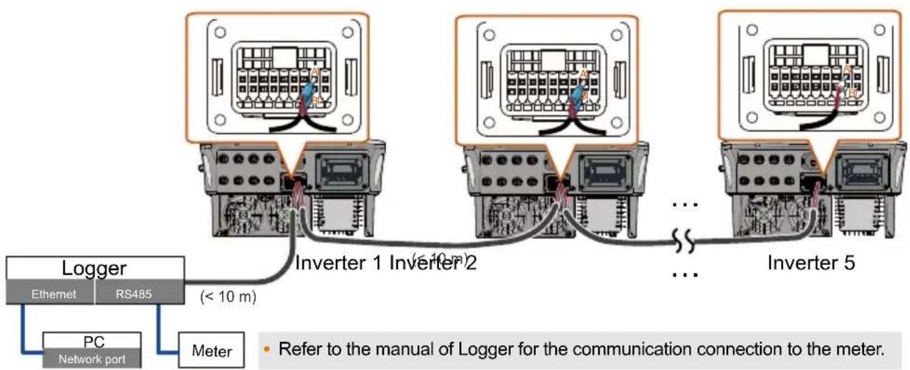
flowchart
graph TD
    A["Logger"] --> B["Ethernet"]
    A --> C["RS485"]
    D["PC Network port"] --> E["Meter"]
    F["Inverter 1 Inverter 2"] --> G["< 10 m"]
    H["Inverter 2"] --> I["< 10 m"]
    J["Inverter 5"] --> K["..."]
    G --> L["..."]
    I --> L
    K --> L
    style A fill:#f9f,stroke:#333
    style D fill:#f9f,stroke:#333
    style F fill:#f9f,stroke:#333
    style H fill:#f9f,stroke:#333
    style J fill:#f9f,stroke:#333
    style B fill:#ccf,stroke:#333
    style C fill:#ccf,stroke:#333
    style E fill:#ccf,stroke:#333
    style G fill:#ccf,stroke:#333
    style I fill:#ccf,stroke:#333
    style K fill:#ccf,stroke:#333
    style L fill:#ccf,stroke:#333
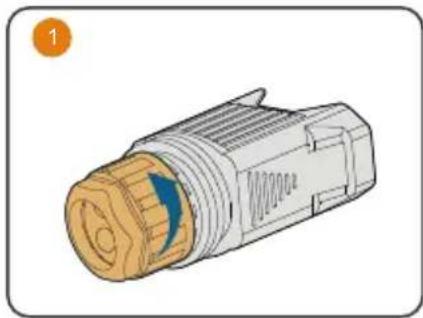
Ripple control
natural_image
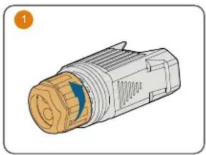
Illustration of a mechanical connector with a yellow gear and blue arrow indicating direction (no text or symbols)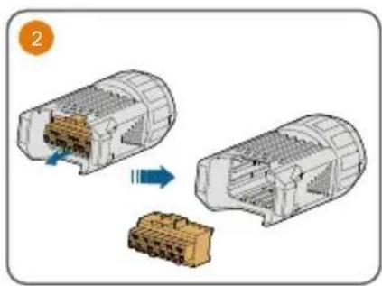
natural_image
Diagram showing two views of a connector assembly with internal components and a blue arrow indicating transformation (no text or symbols)
natural_image
Exploded view diagram of an electric motor assembly with a close-up inset showing internal components (no text or labels)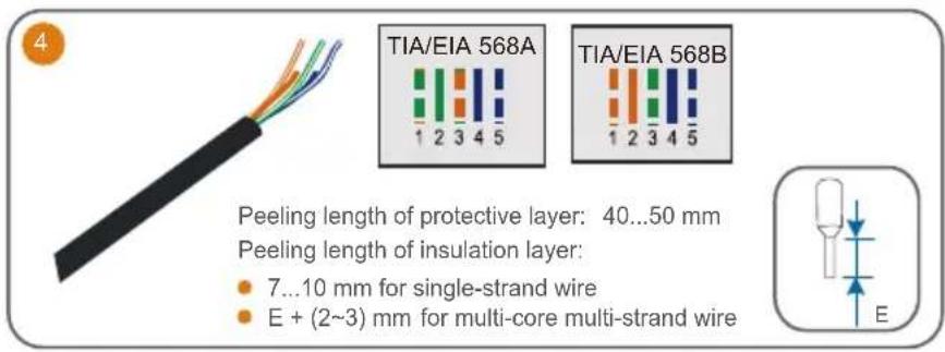
text_image
TIA/EIA 568A 1 2 3 4 5 TIA/EIA 568B 1 2 3 4 5 Peeling length of protective layer: 40...50 mm Peeling length of insulation layer: • 7...10 mm for single-strand wire • E + (2~3) mm for multi-core multi-strand wire
text_image
5 For multi-core multi-strand wire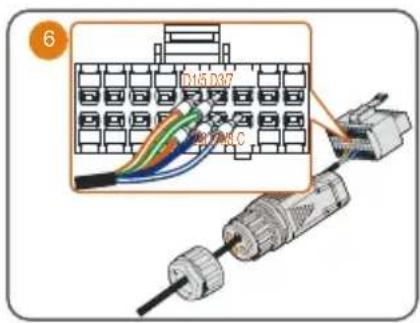
text_image
D15.037 280.000°C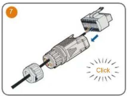
text_image
7 Click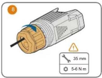
text_image
8 35 mm 5-6 N m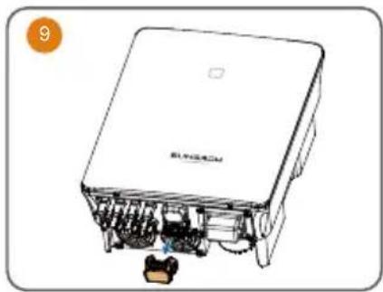
natural_image
Line drawing of a device with internal components and a small object, no visible text or symbols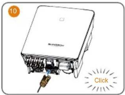
text_image
10 ClickPower on / Ein / Accensione / Allumer / Schakel in / Włącznik / Effekt på / Virta kytketty / Ligação / Ligar / Encendido / Encendido / Включение питания
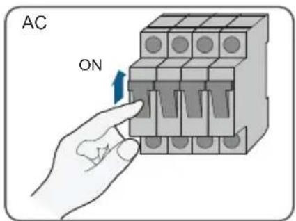
text_image
AC ON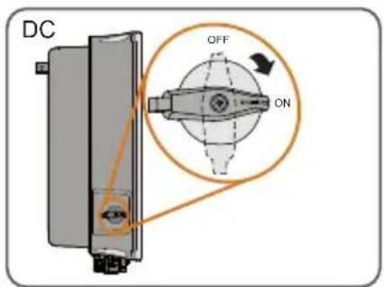
text_image
DC OFF ON
text_image
iSolarCloud AppLED indicator / LED-Anzeigetafel / Indicatore LED / Voyants LED / Led-indicators / Kontrolki LED / LED-indikator / Merkkivalo / Indicador de LED / Indicador LED / Indicador LED / Indicador LED / ЖК-панель
LED indicator LED state Definition

ON The inverter is normally running.
Flashing The inverter is at standby or startup state (not feeding power into the gird).

ON A system fault has occurred.

OFF Both the AC and DC sides are powered down.

text_image
QR code with embedded orange circular logo containing a document icon in the center.More information in the QR code or at http://support.sungrowpower.com/