SG36CX-US - Solar panel Sungrow - Free user manual and instructions
Find the device manual for free SG36CX-US Sungrow in PDF.

| Type | Grid-tied solar inverter |
| Model | SG36CX-US |
| Brand | Sungrow |
| Rated Power | 36 kW |
| Max. DC Input Power | 48 kW |
| Max. DC Voltage | 1000 V |
| MPPT Voltage Range | 200 – 800 V |
| Number of MPP Trackers | 2 |
| Max. Efficiency | 98.7% |
| Weight | 62 kg |
| Dimensions (W x H x D) | 620 x 740 x 310 mm |
| Enclosure Rating | NEMA 4X |
| Operating Temperature Range | -25°C to +60°C |
| Cooling Method | Smart air cooling |
| Display | LCD & LED indicators |
| Communication Interfaces | RS485, Wi-Fi (optional), Ethernet (optional) |
| AC Output Voltage | 480 V, 3-phase |
| AC Frequency | 60 Hz |
| Total Harmonic Distortion (THD) | < 3% |
| Safety Certifications | UL 1741, IEEE 1547, CSA C22.2 No. 107.1 |
| Warranty | 10 years (extendable) |
| Maintenance | Clean air vents and check connections annually |
| Spare Parts Availability | Fan kit, communication board, and power module available |
| Repairability | Modular design; replaceable components |
Frequently Asked Questions - SG36CX-US Sungrow
User questions about SG36CX-US Sungrow
0 question about this device. Answer the ones you know or ask your own.
Ask a new question about this device
Download the instructions for your Solar panel in PDF format for free! Find your manual SG36CX-US - Sungrow and take your electronic device back in hand. On this page are published all the documents necessary for the use of your device. SG36CX-US by Sungrow.
USER MANUAL SG36CX-US Sungrow
PV Grid-Connected Inverter
SG36_60CX-US
natural_image
Exterior view of a SunGROW industrial control unit with black and white casing (no visible text or symbols on main body)All Rights Reserved
All Rights Reserved
No part of this document can be reproduced in any form or by any means without the prior written permission of Sungrow Power Supply Co., Ltd(hereinafter "SUNGROW").
Trademarks
SUNGROW and other Sungrow trademarks used in this manual are owned by Sungrow Power Supply Co., Ltd.
All other trademarks or registered trademarks mentioned in this document are owned by their respective owners.
Software Licenses
- It is prohibited to use data contained in firmware or software developed by SUNGROW, in part or in full, for commercial purposes by any means.
- It is prohibited to perform reverse engineering, cracking, or any other operations that compromise the original program design of the software developed by SUNGROW.
Sungrow Power Supply Co., Ltd.
Address: No.1699 Xiyou Rd., New & High Tech Zone, Hefei, 230088, China.
Email: info@sungrow.cn
Tel: +86 551 6532 7834
Website: www.sungrowpower.com
About This Manual
The manual mainly describes the product information, guidelines for installation, operation and maintenance. The manual cannot include complete information about the photovoltaic (PV) system.
You can get additional information about other devices at www.sungrowpower.com or on the webpage of the respective component manufacturer.
Validity
This manual is valid for the following inverter types:
- SG36CX-US
- SG60CX-US
They will be referred to as "inverter" hereinafter unless otherwise specified.
Target Group
This manual is intended for:
- qualified personnel who are responsible for the installation and commissioning of the inverter; and
- inverter owners who will have the ability to interact with the inverter.
How to Use This Manual
Read the manual and other related documents before performing any work on the inverter is carried out. Documents must be stored carefully and be available at all times.
The contents of the manual will be periodically updated or revised due to the product development. It is possible that there could be changes of manual content in subsequent inverter editions. The latest manual can be acquired via visiting the website at www.
sungrowpower.com.
Symbols
Important instructions contained in this manual should be followed during installation, operation and maintenance of the inverter. They will be highlighted by the following symbols.
Symbol Explanation
| DANGER | Indicates a hazard with a high level of risk that, if not avoided, will result in death or serious injury. |
| WARNING | Indicates a hazard with a medium level of risk that, if not avoided, could result in death or serious injury. |
| CAUTION | Indicates a hazard with a low level of risk that, if not avoided, could result in minor or moderate injury. |
Symbol Explanation
NOTICE
Indicates a situation that, if not avoided, could result in equipment or property damage.

Indicates additional information, emphasized contents or tips that may be helpful, e.g. to help you solve problems or save time.
Contents
All Rights Reserved ....I
About This Manual....II
1 Safety ....1
1.1 PV Panels....1
1.2 Utility Grid ....1
1.3 Inverter 2
1.4 Skills of Qualified Personnel ....3
2 Product Introduction ....4
2.1 Intended Usage....4
2.2 Product Introduction....5
2.2.1 Model Description ....5
2.2.2 Appearance....6
2.2.3 Dimensions 7
2.2.4 LED Indicator Panel 7
2.2.5 DC Switch 8
2.3 Circuit Diagram 9
2.4 Function Description ......9
3 Unpacking and Storage 11
3.1 Unpacking and Inspection 11
3.2 Identifying the Inverter 11
3.3 Scope of Delivery 12
3.4 Inverter Storage 13
4 Mechanical Mounting ....14
4.1 Safety During Mounting....14
4.2 Location Requirements ....14
4.2.1 Installation Environment Requirements....15
4.2.2 Carrier Requirements ....16
4.2.3 Installation Angle Requirements ....17
4.2.4 Installation Clearance Requirements ....17
4.3 Installation Tools....20
4.4 Moving the Inverter ....21
4.4.1 Manual Transport....21
4.4.2 Hoisting Transport....22
4.5 Dimensions of mounting-bracket.....23
4.6 PV Tracker-Mounted Installation 24
4.6.1 Preparation Before Mounting 24
4.6.2 Mounting Steps....24
4.7 Wall-Mounted Installation 26
4.7.1 Preparation Before Mounting 26
4.7.2 Mounting Steps....27
5 Electrical Connection ....30
5.1 Safety Instructions ....30
5.2 Terminal Description ....30
5.3 Electrical Connection Overview 31
5.4 Additional Grounding Connection....33
5.4.1 Additional Grounding Requirements ....33
5.4.2 Connection Procedure....34
5.5 AC Cable Connection ....35
5.5.1 AC Side Requirements 35
5.5.2 Requirements for OT/DT Terminal 36
5.5.3 Aluminium Cable Requirements 36
5.5.4 Connection Procedure....37
5.6 DC Cable Connection ....40
5.6.1 PV Input Configuration 41
5.6.2 Connection Procedure....41
5.6.3 Installing the PV Connectors ....43
5.7 Communication Junction Box 44
5.7.1 Remove the Junction Box ....44
5.7.2 Install the Junction Box....45
5.8 Communication Wiring Board 45
5.9 RS485 Communication ....45
5.9.1 Interface Description ....45
5.9.2 RS485 Communication System....46
5.9.3 Connection Procedure(Crimp)....48
5.9.4 Connection Procedure (RJ45 Ethernet Port)....50
5.10 Dry Contact Connection ....52
5.10.1 Dry Contact Function....52
5.10.2 Wiring Procedure ....54
5.11 Communication Module Connection (optional) 54
5.12 Module-Level Rapid Shutdown Device Connection (Optional) .....55
5.12.1 Module-Level Rapid Shutdown System Introduction....55
5.12.2 Module-Level Rapid Shutdown Device Connection ....55
6 Commissioning 56
6.1 Inspection before Commissioning ....56
6.2 Commissioning Procedure 56
6.3 Module-Level Rapid Shutdown Commissioning (Optional) 56
7 iSolarCloud App ....58
7.1 Brief Introduction ....58
7.2 Download and Install....58
7.3 Login 59
7.3.1 Requirements 59
7.3.2 Login Steps 59
7.4 Function Overview....63
7.5 Home page 63
7.6 Running Information 66
7.7 History Record 67
7.7.1 Fault and Alarm Records 68
7.7.2 Yields Records....69
7.7.3 Event Records 70
7.8 More....70
7.8.1 Parameter Setting .....71
7.8.2 Firmware Update ....78
7.8.3 Changing Password 78
8 System Decommissioning 80
8.1 Disconnecting the Inverter....80
8.2 Dismantling the Inverter 80
8.3 Disposal of the Inverter 81
9 Troubleshooting and Maintenance 82
9.1 Troubleshooting 82
9.2 Maintenance 92
9.2.1 Routine Maintenance 93
9.2.2 Maintenance Instruction....93
10 Appendix 96
10.1 Technical Data....96
10.2 Wring Distance of DI Dry Contact....98
10.3 Quality Assurance 99
10.4 Contact Information ....100
1 Safety
The inverter has been designed and tested strictly according to international safety regulations. Read all safety instructions carefully prior to any work and observe them at all times when working on or with the inverter.
Incorrect operation or work may cause:
- Injury or death to the operator or a third party; or
- Damage to the inverter and other property of the operator or a third party.
All detailed work-related safety warnings and notes will be specified at critical points in this manual.

The safety instructions in this manual cannot cover all the precautions that should be followed. Perform operations considering actual onsite conditions.
SUNGROW shall not be held liable for any damage caused by violation of the safety instructions in this manual.
1.1 PV Panels
! DANGER
PV strings will produce electrical power when exposed to sunlight and can cause a lethal voltage and an electric shock.
• Always keep in mind that the inverter is dual power supplied. Electrical operators must wear proper personal protective equipment: helmet, insulated footwear, glove, etc.
- Before touching the DC cables, operator must use a measuring device to ensure that the cable is voltage-free.
- Follow all warnings on the PV strings and in its manual.
1.2 Utility Grid
Please follow the regulations related to the utility grid to which the inverter will be connected.
NOTICE
All electrical connections must be in accordance with local and national standards. Only with the permission of the utility grid may the inverter be connected to the utility grid.
1.3 Inverter
! DANGER
Danger to life from electric shocks due to live voltage
- Do not open the enclosure at any time. Unauthorized opening will void guarantee and warranty claims and in most cases terminate the operating license.
WARNING
Risk of inverter damage or personal injury
- Do not pull out the PV connectors when the inverter is running.
- Wait at least 5 minutes for the internal capacitors to discharge. Ensure that there is no voltage or current before pulling any connector.
WARNING
All safety instructions, warning labels, and nameplate on the inverter:
- Must be clearly legible.
- Should not be removed or covered.
CAUTION
Risk of burns due to hot components!
Do not touch any hot parts (such as heat sink) during operation. Only the DC switch can safely be touched at any time.
NOTICE
Only qualified personnel can perform the country setting.
- Unauthorized alteration of the country setting may cause a breach of the type-certificate marking.
By touching the electronic components, you may damage the inverter. For inverter handling, be sure to:
- avoid any unnecessary touching.
- wear a grounding wristband before touching any connectors.
Warning Label
| Label | Description |
 | Danger to life due to high voltages!Only qualified personnel can open and service the inverter. |
 | Disconnect the inverter from all the external power sources before service! |
 | There is a danger from a hot surface that may exceed 60°C. |
 | Check the user manual before service! |
1.4 Skills of Qualified Personnel
All installations should be performed by qualified personnel. They should have:
- Training in the installation and commissioning of the electrical system, as well as the dealing with hazards
- Knowledge of the manual and other related documents
- Knowledge of the local regulations and directives
2 Product Introduction
2.1 Intended Usage
SG36CX-US, SG60CX-US, a transformerless three-phase PV grid-connected inverter, is an integral component in the PV power system.
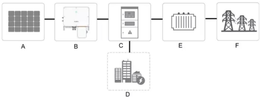
The inverter is designed to convert the DC power generated from the PV modules into grid-compatible AC power and provide it to local loads or export it into the utility grid. The intended usage of the inverter is illustrated in "figure 2-1 Inverter application in PV power system".
flowchart
graph LR
    A[" Solar Panel A "] --> B[" Power Supply Unit B "]
    B --> C[" Control Panel C "]
    C --> D[" Power Transmission Tower E "]
    D --> F[" Power Transmission Tower F "]
    style A fill:#f9f,stroke:#333
    style B fill:#ccf,stroke:#333
    style C fill:#cfc,stroke:#333
    style D fill:#fcc,stroke:#333
    style E fill:#ffc,stroke:#333
    style F fill:#fcc,stroke:#333
figure 2-1 Inverter application in PV power system
WARNING
Inverter cannot connect the PV strings whose positive and negative terminals need to be grounded.
Do not connect any local load between the inverter and the AC circuit breaker. During the installation and operation of the inverter, please ensure that the positive or negative polarities of PV strings do not short-circuit to the ground. Otherwise, an AC or DC short-circuit may occur, resulting in equipment damage. The damage caused by this is not covered by the warranty.
| Item | Description | Note |
| A | PV strings | Monocrystalline silicon, polycrystalline silicon and thin-film without grounding. |
| B Inverter | SG36CX-US, SG60CX-US. | |
| C | Grid connection cabinet | Includes devices such as AC circuit breaker, SPD, metering device. |
| D Load | Power consumption from local facilities. | |
| E | Transformer | Lift the voltage of the power to the grid level. |
| F | Utility grid | TN-C, TN-S, TN-C-S, TT, IT. |
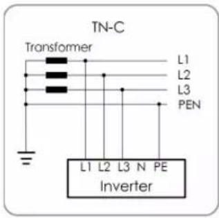
text_image
TN-C Transformer L1 L2 L3 PEN L1 L2 L3 N PE Inverter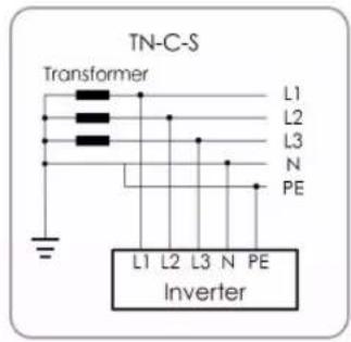
text_image
TN-C-S Transformer L1 L2 L3 N PE L1 L2 L3 N PE Inverter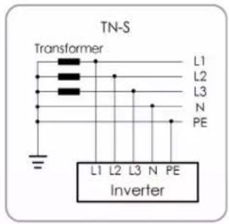
text_image
TN-S Transformer L1 L2 L3 N PE L1 L2 L3 N PE Inverter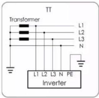
text_image
TT Transformer L1 L2 L3 N L1 L2 L3 N PE Inverter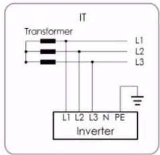
text_image
IT Transformer L1 L2 L3 L1 L2 L3 N PE inverterNOTICE
In an IT system, the inverter does not detect AC Side Ground Faults. Only DC Side Ground Fault protection is provided by the inverter. Additional AC ground fault detection must be added externally to the inverter according to local requirements e.g. NEC 250.21.
2.2 Product Introduction
2.2.1 Model Description
The device model description is as follows (Take SG36CX-US as an example):
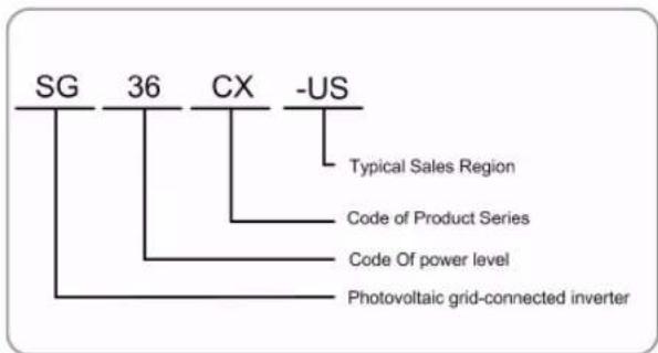
flowchart
graph TD
    A["SG"] --> B["Typical Sales Region"]
    C["36"] --> D["Code of Product Series"]
    E["CX"] --> F["Code Of power level"]
    G["-US"] --> H["Photovoltaic grid-connected inverter"]
| Model | Nominal Output Power Nominal Grid Voltage |
| SG36CX-US 36000W | 3/N/PE, 277/480 VAC |
| SG60CX-US 60000W |
The device model can be found on the nameplate attached to the side of the inverter. For details, refer to "3.2 Identifying the Inverter".
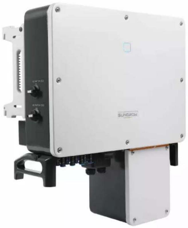
2.2.2 Appearance
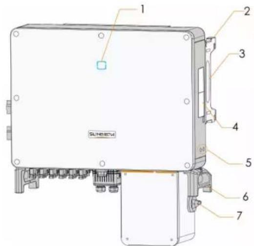
text_image
1 2 3 4 5 6 7 SUNHENG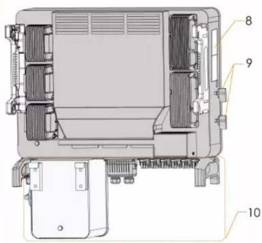
text_image
Technical diagram of a device rear panel with numbered components labeled 8, 9, and 10*The image shown here is for reference only. The actual product you receive may differ.
| No. | Name | Description |
| 1 | LED indicator panel | HMI interface to indicate the present working state of the inverter. |
| 2 | Mounting ears | 4PCS, used to hang the inverter onto the mounting-bracket. |
| 3 | Side handles | 2PCS, used to move the inverter. |
| 4 | Labels | Warning symbols. |
| 5 | Additional grounding terminals | 2PCS, use at least one of them to ground the inverter. |
| 6 | Bottom handles | 2PCS, used to move the inverter. |
| 7 | AC switches | To disconnect the AC power from grid safely. |
| 8 | Labels | Nameplate, and QR code. |
| 9 | DC switches | To disconnect the DC power from PV safely. |
| 10 | Wiring area | AC terminals, DC terminals, and communication terminals. For details, refer to"5.2 Terminal Description". |
2.2.3 Dimensions
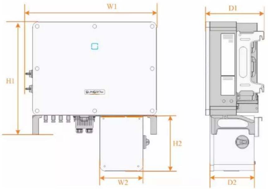
text_image
W1 H1 SUNGROW D1 H2 W2 D2figure 2-2 Dimensions of the Inverter
*The image shown here is for reference only. The actual product you receive may differ.
| Type | Dimensions (W1*H1*D1) | Dimensions (W2*H2*D2) | Weight |
| SG36- | 702 * 595 * 310 mm | (27.6" 231 * 295 * 234 mm | (9.1" 54kg(119.05lbs) |
| CX-US | 23.4" * 12.2") | * 11.6" * 9.2") | |
| SG60- | 782 * 645 * 310 mm | (30.7" 231 * 295 * 234 mm | (9.1'65kg(143.3lbs) |
| CX-US | 25.4" * 12.2") | * 11.6" * 9.2") |
2.2.4 LED Indicator Panel
As an HMI, the LED indicator panel on the front of the inverter can indicate the present working state of the inverter.
table 2-1 LED indicator description
| LED indicator | LED state Definition | |
| ON | The device is connected to the grid and operating normally. | |
 | Fast blink(Period:About 0.2s) | The Bluetooth communication is connected and there is data communication.No system fault occurs. |
Blue | Slow flash(Period:About 2s)ON | The device is in standby or startup state (not export power into the grid).A fault occurred and the device cannot connect t the grid. |
| Twinkling | The Bluetooth communication is connected and there is data communication. System fault occurs. | |
 | OFF | Both the AC and DC sides are powered down. |
| OFF | ||
WARNING
The inverter may carry voltage in case of fault. Test the inverter before performing operation on it.
2.2.5 DC Switch
The DC switch is used to disconnect the DC current safely whenever necessary. The SG36CX-US and SG60CX-US are equipped with two DC switches separately controlling a group of DC inputs. The correspondence is as follows:
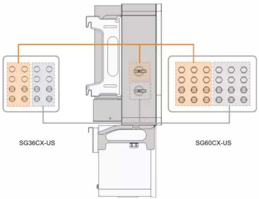
text_image
SG36CX-US SG60CX-US
Turn the DC switches to the ON position before restarting the inverter.
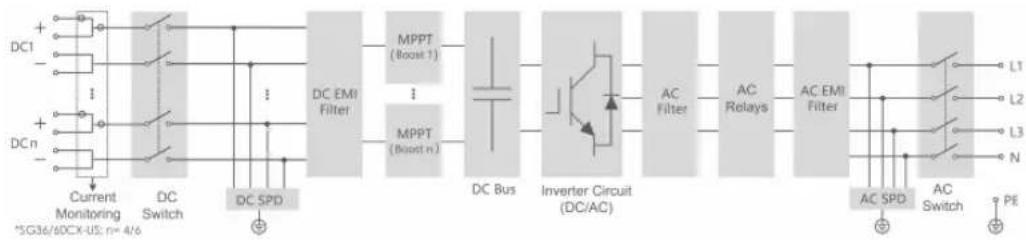
2.3 Circuit Diagram
The MPPT is utilized for DC input to ensure the maximum power from the PV array at different PV input conditions. The inversion circuit converts the DC power into AC power and feeds the AC power into the utility grid through the AC terminal. The protection circuit is equipped to ensure the safe operation of the device and personal safety.
The following Figure shows the main circuit of the inverter.
flowchart
graph LR
    A["DC1"] --> B["Current Monitoring"]
    C["DCn"] --> D["DC Switch"]
    B --> E["DC SPD"]
    D --> E
    E --> F["DC EMI Filter"]
    F --> G["MPPT (Boost 1)"]
    F --> H["MPPT (Boost n)"]
    G --> I["DC Bus"]
    H --> I
    I --> J["Inverter Circuit (DC/AC)"]
    J --> K["AC Filter"]
    K --> L["AC Relays"]
    L --> M["AC EMI Filter"]
    M --> N["L1"]
    M --> O["L2"]
    M --> P["L3"]
    M --> Q["N"]
    N --> R["PE"]
    O --> R
    P --> R
    Q --> R
    style A fill:#f9f,stroke:#333
    style C fill:#f9f,stroke:#333
    style B fill:#ccf,stroke:#333
    style D fill:#ccf,stroke:#333
    style E fill:#cfc,stroke:#333
    style F fill:#fcc,stroke:#333
    style G fill:#cff,stroke:#333
    style H fill:#cff,stroke:#333
    style I fill:#ffc,stroke:#333
    style J fill:#ffc,stroke:#333
    style K fill:#ffc,stroke:#333
    style L fill:#ffc,stroke:#333
    style M fill:#ffc,stroke:#333
    style N fill:#cfc,stroke:#333
    style O fill:#cfc,stroke:#333
    style P fill:#cfc,stroke:#333
    style Q fill:#cfc,stroke:#333
figure 2-3 Circuit diagram
2.4 Function Description
The inverter is equipped with the following functions:
Conversion function
The inverter converts the DC current into grid-compatible AC power and provide it to local loads or export it into the grid.
Data storage
The inverter records running information, error records, etc.
Parameter configuration
The inverter provides various settable parameters. Users can set parameters via the App to meet the requirements.
Communication interface
The inverter is designed with standard RS485 communication interfaces.
The standard RS485 communication interfaces are used to establish communication connection with monitoring devices and upload monitoring data by using communication cables.
After communication connection is established, users can view inverter information or set inverter parameters in a certain remote online portal.
Protection Function
The protective functions are integrated in the inverter, including anti-island protection, LVRT/HVRT, DC reversed polarity protection, AC short circuit protection, leakage current protection, DC overvoltage/overcurrent protection, etc.
PID recovery function
The inverter injects compensating voltage to PV strings to recovery PV string performance when no power is generated.
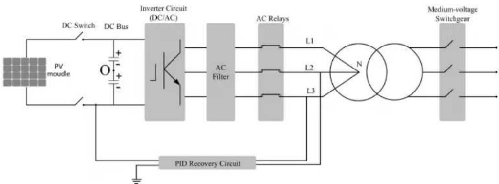
flowchart
graph LR
    A["PV mottle"] --> B["DC Switch"]
    B --> C["DC Bus"]
    C --> D["Inverter Circuit (DC/AC)"]
    D --> E["AC Filter"]
    E --> F["AC Relays"]
    F --> G["N"]
    G --> H["Medium-voltage Switchgear"]
    H --> I["PID Recovery Circuit"]
    I --> J["L1"]
    I --> K["L2"]
    I --> L["L3"]
    J --> D
    K --> D
    L --> D
i
- Before enabling the PID recovery function, make sure the voltage polarity of the PV modules to ground meets requirement. If there are any questions, contact the PV module manufacturer or read its corresponding user manual.
- If the voltage scheme for the PID recovery function does not meet the requirement of corresponding PV modules, the PID function will not work as expected or even damage the PV modules.
- If the PID recovery function is enabled, it only works at night.
• After the PID recovery function is enabled, the voltage of the PV string to ground is 500Vdc by default, and the default value can be modified through the App.
AFCI function
- AFCI activation
This function can be enabled to detect whether arc occurs in the DC cable of the inverter.
- AFCI self-test
This function is intended to detect whether the AFCI function of the inverter is normal.
Rapid Shut Down Function(optional)
The inverter supports cooperation with PV module Rapid Shut Down (RSD) devices. The inverter will trigger the signal to shut down command to RSD devices via Power Line Communication (PLC) once AC switch is off or grid islanding occurs.
3 Unpacking and Storage
3.1 Unpacking and Inspection
The inverter is thoroughly tested and strictly inspected before delivery. Damage may still occur during shipping. Conduct a thorough inspection after receiving the device.
- Check the packing for any visible damage.
- Check the inner contents for damage after unpacking.
- Check the delivery scope for completeness according to the packing list.
Contact SUNGROW or the supplier in case there is any damage or incompleteness.
Do not dispose of the original packing case. It is recommended to store the inverter in it.
3.2 Identifying the Inverter
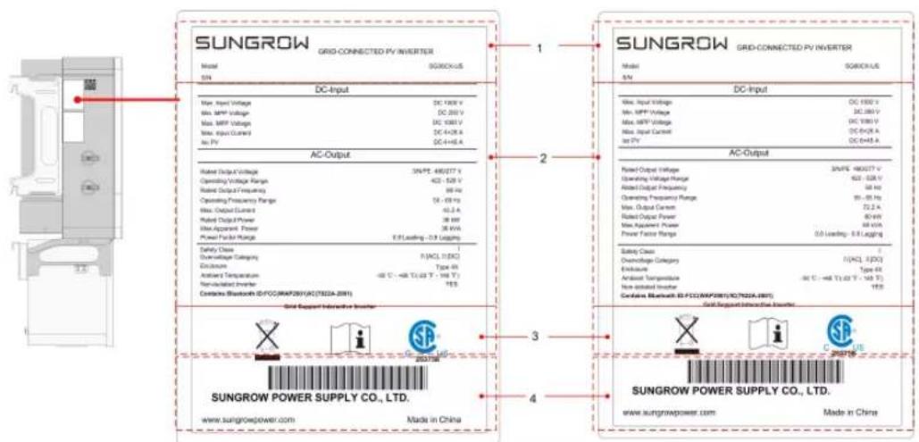
The nameplate can be found on both the inverter and the packing case. It provides information on type of inverter, important specifications, marks of certification institutions, and serial number which are available and identified by SUNGROW.
text_image
SUNGROW GRID-CONNECTED PV INVERTER Model SUGROCKUS SN DC-Input Max. Input Voltage DC 100V Max. MPV Voltage DC 250 V Max. MPV Voltage DC 400V Max. Input Control DC 442K A Max. PV DC 444K A AC-Output Rated Output Voltage 3kV (E) 480277 V Operating Voltage Range 422 - 528 V Rated Output Frequency 98 Hz Operating Frequency Range 15 - 69 Hz Max. Output Current 42.5 A Rated Output Power 38 kHz Max Apparent Power 38 kVA Power Factor Range E/F Leasing: -0.9 L/kg/Hz Safety Class F(ACL 1/5X) Discharge Type 45 Antenna Temperature -40 °C - +48 T / 1.03 V - 100 V Non-Indicated Inverter 105 Contains Bluetooth ID/FCO/MAP201(AC/TSDZA-201) Grid Support Interactive Inverter SUNGROW POWER SUPPLY CO., LTD. www.sungrowpower.com Made in China SUNGROW GRID-CONNECTED PV INVERTER Model SUGROCKUS DC-Input Max. Input Voltage DC 1550 x Max. MPV Voltage DC 280 V Max. MPV Voltage DC 380 V Max. Input Control DC 600A A Max. PV DC 644K A AC-Output Rated Output Voltage 30V (E) 480277 V Operating Voltage Range 422 - 528 V Rated Output Frequency 58 Hz Operating Frequency Range 95 - 69 Hz Max. Output Current 72.2 A Rated Output Power 80 kHz Max. Apparent Power 88 kHz Power Factor Range 0.0 Leasing: E/F Leasing Safety Class F(ACL 1/5X) Discharge Type 45 Exhaust Type 45 Antenna Temperature -40 °C - +48 T / 1.03 V - 100 V Non-Indicated Inverter 105 Contains Bluetooth ID/FCO/MAP201(AC/TSDZA-201) Grid Support Interactive Inverter SUNGROW POWER SUPPLY CO., LTD. www.sungrowpower.com Made in Chinafigure 3-1 Nameplate of Inverters
* The image shown here is for reference only. The actual product you receive may differ.
| Item | Description |
| 1 | SUNGROW logo and product type |
| 2 | Technical data of inverter |
| 3 | Instructions and marks of conformity |
| 4 | Company name, website and country of manufacture |
table 3-1 Description of Icons on the Nameplate
| Icon | Description |
 | Do not dispose of the inverter together with household waste. |
 | Refer to the corresponding instructions. |
 | CSA (US & CA) mark of conformity. |
3.3 Scope of Delivery
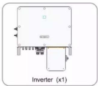
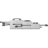
natural_image
Diagram of an inverter (x1) with labeled components and wiring, no readable text or symbols beyond label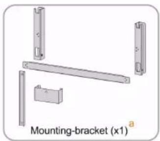
natural_image
Mechanical bracket assembly diagram with mounting bracket (x1) labeled, showing four metal parts and a central rod (no text or symbols beyond label)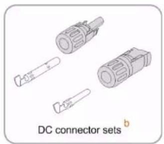
natural_image
Illustration of DC connector sets with exploded view (no text or symbols on components)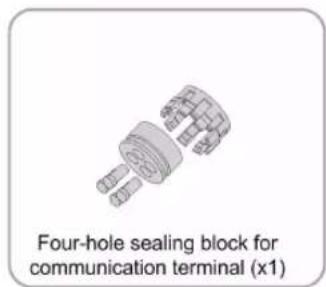
text_image
Four-hole sealing block for communication terminal (x1)
text_image
M10 fastening screw sets (x4)
natural_image
Illustration of various screw and nut components (no text or symbols)
text_image
Documents dfigure 3-2 Scope of Delivery
a. The mounting-bracket includes 2 mounting-bracket components and 1 connecting bar.
b. The SG36CX-US, SG60CX-US are respectively provided with 8, 12 pairs of DC connectors and cord end terminals.
c. The screws include 6 M4×10 screws, 2 M6×65 screws, and 2 M12 hex socket screws.
d. The documents include the quick installation guide, packing list, warranty card, etc.
3.4 Inverter Storage
Proper storage is required if the inverter is not installed immediately.
- Store the inverter in the original packing case with the desiccant inside.
- The storage temperature must be always between -40^ and +70^ , and the storage relative humidity must be always between 0 and 95% , non-condensing.
- In case of stacking storage, the number of stacking layers should never exceed the limit marked on the outer side of the packing case.
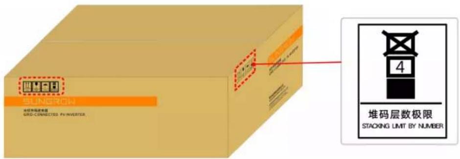
text_image
SINGRON 堆码层数极限 GRID-CONNECTED PV-INVERTER 堆码层数极限 STACKING LIMIT BY NUMBER• The packing case should be upright.
- If the inverter has been stored more than half a year, qualified personnel should thoroughly check and test it before using.
4 Mechanical Mounting
4.1 Safety During Mounting
! DANGER
Ensure there is no electrical connection before installation.
In order to avoid electric shock or other injury, be sure there is no electricity or conduit installations before drilling holes.
CAUTION
Risk of injury due to improper handling
• Always follow the instructions when moving and positioning the inverter.
- Improper operation may cause injuries, serious wounds, or bruise.
System performance loss due to poor ventilation!
- Keep the heat sinks uncovered to ensure heat dissipation performance.
4.2 Location Requirements
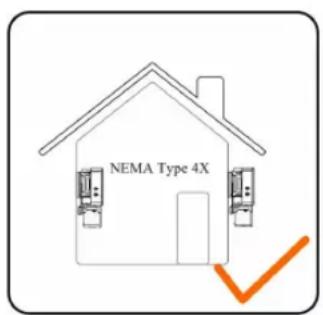
Select an optimal mounting location for safe operation, long service life, and outstanding performance.
- The inverter with NEMA Type 4X protection can be installed both indoors and outdoors.
• Install the inverter in a place convenient for electrical connection, operation, and maintenance.
text_image
NEMA Type 4X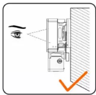
text_image
Diagram showing eye contact with a wall-mounted device, highlighting the eye and a checkmark indicating inspection or verification.4.2.1 Installation Environment Requirements
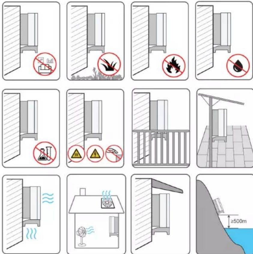
- The inverter produces noise during operation, thus it is not recommended to install it in places for residential purpose. If this cannot be avoided, it is recommended to install the inverter in a place over 25 meters away from the residential area, or take noise mitigation measures.
- If the inverter is installed in a place with lush vegetation, weed on a regular basis. In addition, the ground beneath the inverter needs to undergo certain treatment, such as laying cement or gravel, etc. (an area of 3m × 2.5m is recommended).
- Do not install the inverter in an environment with flammables, explosives, or smoke.
- Do not install the inverter in places prone to water leak, e. g., under the air-conditioner vent, the air vent, or the cable outlet window of the machine room, so as to prevent device damage or short circuit caused by intrusion of water.
- Do no install the inverter in a place with corrosives such as corrosive gas and organic solvent, etc.
- When the inverter is running, its surface may carry high voltages or get very hot. Do not touch it; otherwise, it may lead to burns or electric shocks.
- Do not install the inverter in a place that is easy to reach for people.
• Install the inverter in a place with shelter, so as to prevent it from getting impacted by direct sunlight and severe weather (e. g. snow, rain, and lightning). The inverter will derate in high temperatures for self-protection. If installed in a place directly exposed to sunlight, as the temperature rises, the inverter may witness power reduction.
- Good heat dissipation is very important to the inverter. Please install the inverter in a ventilated environment.
- If the inverter needs to be installed in a closed environment, please install additional heat dissipation or ventilation devices. During the running of the inverter, the room temperature should not be higher than the outdoor ambient temperature.
- Please consult SUNGROW before installing inverters outdoors in areas prone to salt damage, which mainly are coastal areas within 500 meters of the coast. The sedimentation amount of salt spray is correlated to the characteristics of the seawater, sea winds, precipitation, air humidity, topography, and forest coverage in the adjacent sea areas, and there are substantial differences between different coastal areas.
- Do not install the inverter in an environment contaminated with chemicals such as halogen and sulfide.
- Do not install the inverter in an environment with vibration and strong electromagnetic field. Strong-magnetic-field environments refer to places where magnetic field strength measures over 30 A/m.
- In dusty environments such as places full of dust, smoke, or floc, particles may cling to the device's air outlet or heat sink, thus impacting its heat dissipation performance or even getting it damaged. Therefore, do not install the inverter in dusty environments. If the inverter has to be installed in such environments, please clean its fans and heat sink on a regular basis to ensure a good heat dissipation performance.
- The inverter should be installed in a place over 30 m away from the third party wireless communication facilities and environments for living.
- The average temperature approximately 1 m around the inverter should be taken as its operating temperature. The temperature and humidity should meet the requirements below:
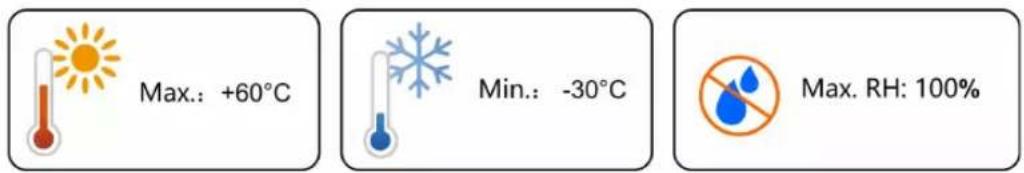
text_image
Max.: +60°C Min.: -30°C Max. RH: 100%4.2.2 Carrier Requirements
Do not install the inverter on a carrier that may vibrate in resonance, so as to avoid making bigger noise.
The installation carrier should meet the following requirements:
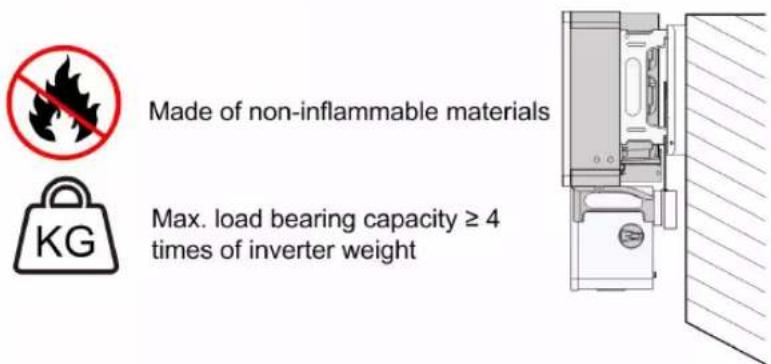
text_image
Made of non-inflammable materials Max. load bearing capacity ≥ 4 times of inverter weight KG4.2.3 Installation Angle Requirements
Inverter vertically or at a minimum back tilt of 10^ . Forward installation or upside down installation is prohibited.
Please consult SUNGROW before tilting backwards the inverter and install it in floating power plants.
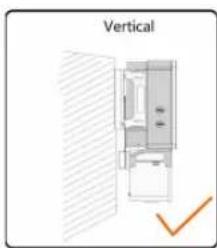
natural_image
Diagram of a refrigerator interior with a checkmark indicating vertical alignment (no text or symbols on the diagram itself)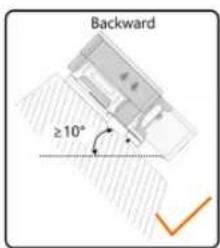
text_image
Backward ≥10°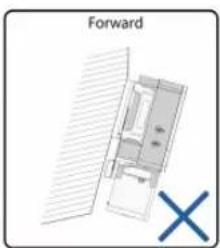
text_image
Forward X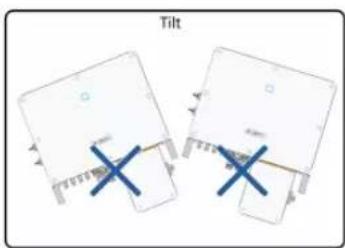
text_image
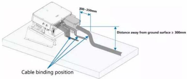
TiltIn case the installation site is a level surface, mount the inverter to the horizontal-mounting bracket to meet the mounting angle requirements, as shown in the Figure below.
text_image
300-350mm Distance away from ground surface ≥ 300mm Cable binding position
Take the following items into account when designing the bracket scheme:
- Consider onsite climate conditions and take anti-snow and anti-rain measures if necessary.
- Ensure that the waterproof connectors are at least 300mm higher than the ground surface.
- Bind the cables at the positions 300\~350mm away from the DC connector, AC waterproof terminal, and communication waterproof terminal.
- The various waterproof terminals should be tightened in accordance with the torque requirements in this manual to ensure that they are tight and sealed.
Contact SUNGORW if you have any question.
About X-RACK ordering issues, please contact you local SUNGROW Sales or SUNGROW authorized distributors.
4.2.4 Installation Clearance Requirements
- Reserve enough clearance around the inverter to ensure sufficient space for heat dissipation. (The fans are maintained on the left side of the inverter, and a larger clearance is required.)
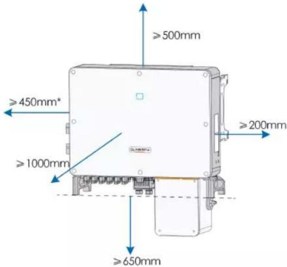
text_image
≥500mm ≥450mm* ≥1000mm ≥200mm ≥650mm* The distance can be shortened to 200mm according to onsite conditions. In case the distance is less than 450mm, remove the inverter from the mounting-bracket or wall before maintaining fans.
The distance between the bottom of the inverter and the ground surface is determined according to the bending radius of the AC cable used and the installation environment. In addition, the following conditions must be met:
- The distance between the bottom of the inverter and the ground surface is not less 650mm.
- The AC cable is vertically led into the cabinet, and the straight length is not less 200mm.

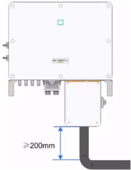
text_image
SUNCRON ≥200mmIf there are any questions, please consult the AC cable manufacturer.
- In case of multiple inverters, reserve specific clearance between the inverters, as shown below.
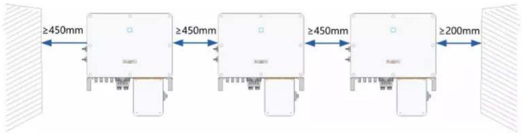
text_image
≥450mm ≥450mm ≥450mm ≥200mm- In case of back-to-back installation, reserve specific clearance of at least 500m between the two inverters, as is shown below.
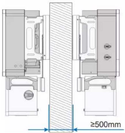
text_image
≥500mm• Install the inverter at an appropriate height for ease of viewing LED indicators and operating switches.
4.3 Installation Tools
Installation tools include but are not limited to the following recommended ones. If necessary, use other auxiliary tools on site.
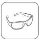
Goggles
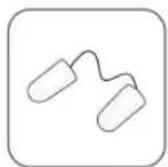
Earplugs
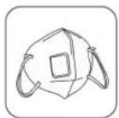
Dust mask
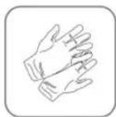
Safety gloves

Safety shoes
Utility knife
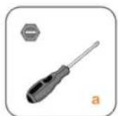
Slotted screwdriver
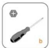
Phillips screwdriver
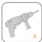
Hammer drill

Pliers

Marker
Level

Rubber mallet
Socket wrench set
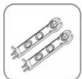
Open-end
wrench
Anti-static wrist strap

Wire cutter

Wire stripper

Hydraulic pliers
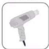
Heat gun

MC4 terminal crimping tool
Connector wrench
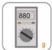
Multimeter
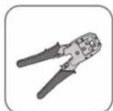
RJ45 crimping tool

Vacuum cleaner
Torx wrench
Allen wrench
table 4-1 Tool Specification
| No. | Specification |
| a | M2/M6 |
| b | M4/M6/M8 |
| c | Drill bit: φ12, φ14 |
| d | Includes sleeve with opening size 16mm |
| e | Opening:13mm, 16mm |
| f | Crimp range 4~6mm |
| g | Range≥1100Vdc |
| h | 15mm |
4.4 Moving the Inverter
Move the inverter to the specified position before installation. The inverter can be moved manually or via a hoist.
4.4.1 Manual Transport
Lift and move the inverter to the destination by using the side handles and bottom handles.
natural_image
Illustration of hands assembling a Sunitech industrial control box (no text or symbols on the device itself)CAUTION
Inappropriate moving operation may cause personal injury!
- It is recommended that at least two installers carry the inverter together and wear protective equipment such as smash-proof shoes and gloves
• Always beware of the gravity center of the inverter and avoid tipping.
NOTICE
The ground surface on which the inverter is to be placed should be covered with a sponge pad, foam cushion or the like to prevent the inverter bottom from getting scratched or other damages.
4.4.2 Hoisting Transport
Step 1 Release the sealing screws on the mounting ears and store them properly. Anchor two M12 thread lifting rings to the hangers of the inverter.
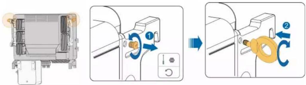
text_image
Diagram illustrating the process of a mechanical device with labeled parts and directional arrows indicating motion or assembly.Step 2 Lead the sling through the two lifting rings and fasten the tie-down strap.
Step 3 Hoist the inverter, and stop to check for safety when the inverter is 100mm above the ground. Continue hoisting the device to the destination after ensuring the safety.
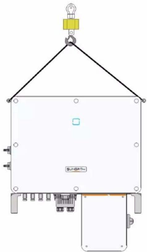
natural_image
Technical line drawing of a crane lifting a component labeled SUNGROW, with no readable text or symbols beyond the label.Step 4 Remove the lifting rings and reassemble the sealing screws removed in Step 1.
CAUTION
Keep the inverter balanced throughout the hoisting process and avoid collisions with walls or other objects.
Stop hoisting in the event of severe weather, such as heavy rain, thick fog, or strong wind.

The lifting rings and the sling are not within the delivery scope.
-- End
4.5 Dimensions of mounting-bracket
Dimensions of the assembled mounting-bracket are as follows:
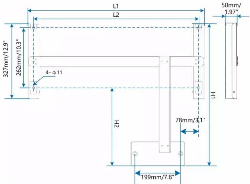
text_image
L1 L2 50mm/ 1.97" 327mm/12.9" 262mm/10.3" 4-φ11 H1 H2 78mm/3.1" 199mm/7.8"figure 4-1 Dimensions of mounting-bracket
| Type | L1 | L2 | H1 | H2 |
| SG36CX-US | 687mm/26.7" | 640mm/25.2" | 564mm/22.2" 235mm/9.3" | |
| SG60CX-US | 767mm/30.2" | 720mm/28.3" | 614.5mm/24.2" 285mm/11.2" | |
4.6 PV Tracker-Mounted Installation
4.6.1 Preparation Before Mounting
Tools
| Item | Specification |
| Phillips screwdriver/ electric screw driver | M4, M6 |
| Marker | - |
| Level | - |
| Hammer drill | Drill bit: φ12 |
| Socket wrench | Including 16mm socket |
| Wrench | Opening: 16mm |
Spare parts
| Item | Quantity Specification | Source |
| Grub screw | 6 M4×10 | Delivery scope |
| 2 M6×65 | Delivery scope | |
| Bolt assembly | 4 M10 | Delivery scope |
4.6.2 Mounting Steps
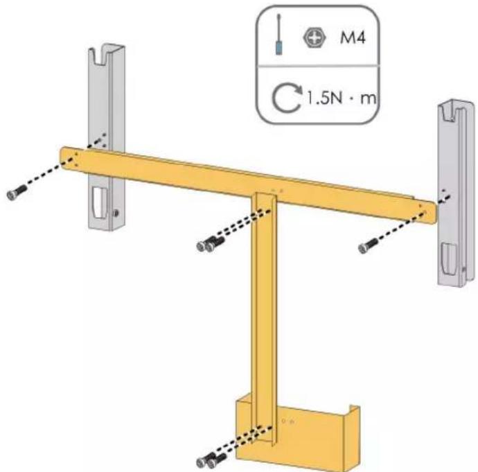
Step 1 Assemble the mounting-bracket by using the connecting bar.
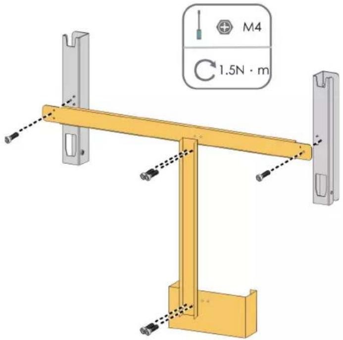
text_image
M4 1.5N · mStep 2 Level the assembled mounting-bracket by using the level, and mark the positions for drilling holes on the PV bracket. Drill the holes by using a hammer drill.
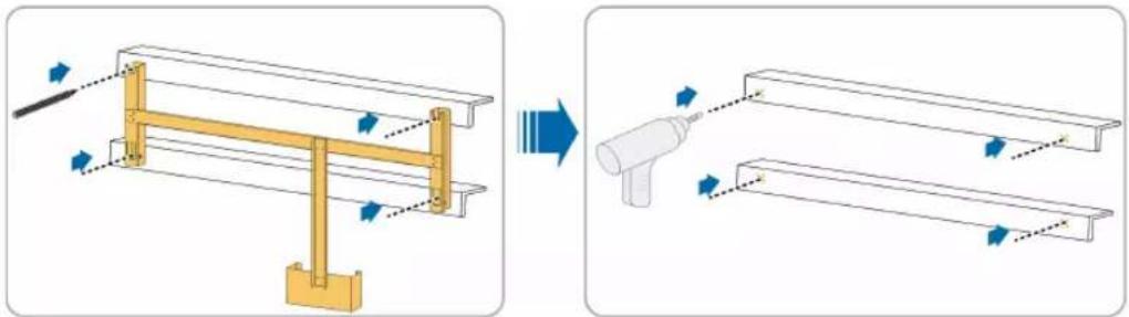
natural_image
Diagram showing structural change from a frame with arrows to a spray bottle (no text or symbols present)Step 3 Secure the mounting-bracket with bolts.
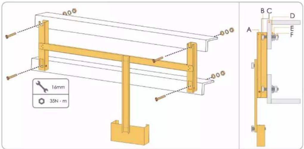
text_image
16mm 35N·mtable 4-2 Fastening sequence
| No. | Components | Description |
| A | Mounting-bracket | - |
| B | Full threaded bolt M10*45 | |
| C | Metal bracket | - |
| D | Flat washer | - |
| E | Spring washer | - |
| F | Hex nuts | - |
Step 4 Take out the inverter from the packing case.
Step 5 Hoist the inverter to the installation position when necessary (refer to "4.4.2 Hoisting Transport"). If the installation position is not high enough, skip performing this step.
Step 6 Hang the inverter to the mounting-bracket and ensure that the mounting ears perfectly engage with the mounting-bracket.
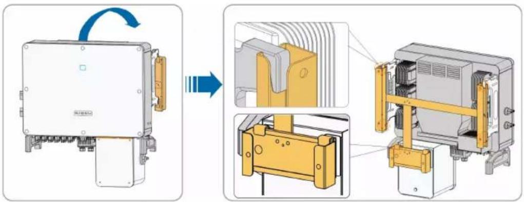
text_image
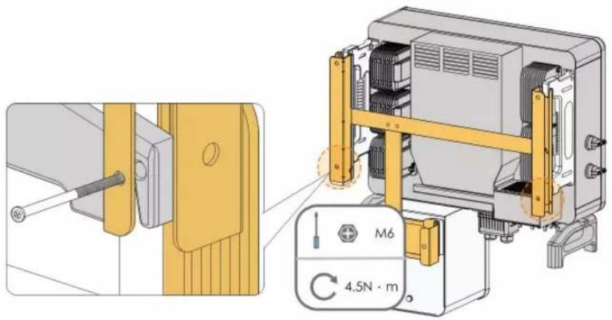
Technical diagram showing assembly of an electrical enclosure with labeled components and directional arrows indicating motion.Step 7 Secure the inverter with two M6×65 screws.
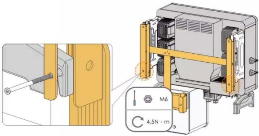
text_image
Technical diagram showing a mechanical assembly with labeled components and a 4.5N·m torque indicator.-- End
4.7 Wall-Mounted Installation
4.7.1 Preparation Before Mounting
Tools
| Item | Specification |
| Phillips screwdriver/ electric screw driver | M4, M6 |
| Marker | - |
| Level | - |
| Hammer drill | Drill bit(Select according to expansion bolt specifications) |
| Socket wrench | Including 16mm socket |
| Wrench | Opening: 16mm |
Spare parts
| Item | Quantity | Specification | Source |
| Grub screw | 6 M4×10 | Delivery scope | |
| 2 M6×65 | Delivery scope | ||
| Expansion bolts | 4 | M10×95(Recommended) | Self-prepared |
4.7.2 Mounting Steps
Step 1 Assemble the mounting-bracket by using the connecting bar.
text_image
M4 1.5N · mStep 2 Level the assembled mounting-bracket by using the level, and mark the positions for drilling holes on the installation site.
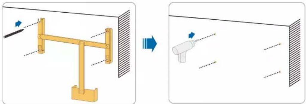
natural_image
Diagram showing a mechanical assembly before and after transformation, with no visible text or symbols.Step 3 Insert the expansion bolts into the holes and secure them with a rubber hammer. Fasten the nut with a wrench to expand the bolt. Remove the nut, spring washer, and flat washer, and store them properly.
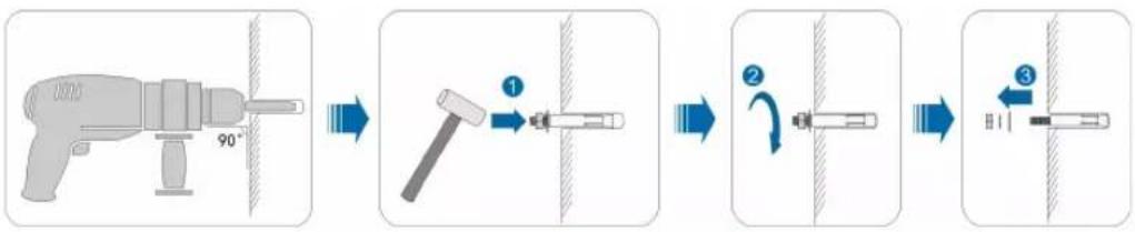
flowchart
graph LR
    A["90°"] --> B["1"]
    B --> C["2"]
    C --> D["3"]
Step 4 Fix the mounting-bracket with the expansion bolts.
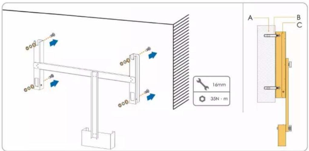
text_image
16mm 35N · m A B Ctable 4-3 Fastening sequence
| Item | Designation | Description |
| A Wall | - | |
| B | Expansion bolt | Fastening the bolt in the sequence of nut, spring washer, flat washer. |
| C | Mounting-bracket | - |
Step 5 Take out the inverter from the packing case.
Step 6 Hoist the inverter to the installation position when necessary (refer to "4.4.2 Hoisting Transport"). If the installation position is not high enough, skip performing this step.
Step 7 Hang the inverter to the mounting-bracket and ensure that the mounting ears perfectly engage with the mounting-bracket.
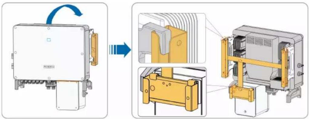
text_image
Technical diagram showing assembly of a device with labeled components and directional arrows indicating motion or transformation.Step 8 Secure the inverter with screws.
text_image
Technical diagram showing mechanical assembly with labeled components and a 4.5N·m torque indicator-- End
5 Electrical Connection
5.1 Safety Instructions
Prior to any electrical connections, keep in mind that the inverter has dual power supplies. It is mandatory for the qualified personnel to wear personal protective equipments (PPE) during the electrical work.
! DANGER
Danger to life due to high voltage inside the inverter!
- The PV string will generate lethal high voltage when exposed to sunlight.
- Before starting electrical connections, disconnect the DC and AC circuit breakers and prevent them from inadvertent reconnection.
- Ensure that all cables are voltage free before performing cable connection.
WARNING
- Any improper operations during cable connection can cause device damage or personal injury.
- Only qualified personnel can perform cable connection.
- All cables must be undamaged, firmly attached, properly insulated and adequately dimensioned.
NOTICE
Comply with the safety instructions related to the PV strings and the regulations related to the utility grid.
- All electrical connections must be in accordance with local and national standards.
- Only with the permission of the utility grid may the inverter be connected to the utility grid.
5.2 Terminal Description
Wiring terminals are at the bottom of the inverter, as shown in the Figure below.
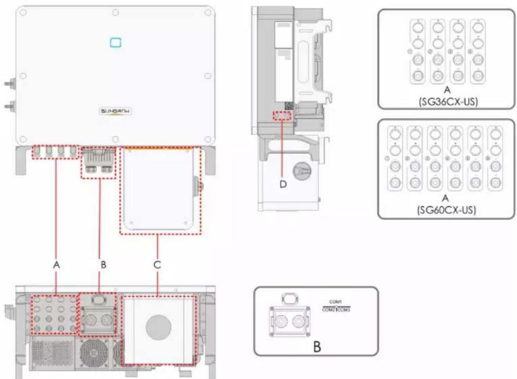
figure 5-1 Wiring terminals
* Figure shown here is for reference only. The actual product you receive may differ!
| Item | Terminal | Mark | Note |
| A PV terminals + / - | MC4 PV connectorSG36CX-US: 8 pairs of terminalsSG60CX-US: 12 pairs of terminals | ||
| B | Communicati-on Terminal | COM1 | For Communication module connection(Optional). |
| COM2 | For digital input and output DI/DO wiring. | ||
| COM3 | For RS485 communication wiring. | ||
| C | AC junction box | — | Remove the protective case and use the junction box in the shipping accessory for wiring. |
| D | Additional grounding terminal |  | 2, use at least one of them to ground the inverter. |
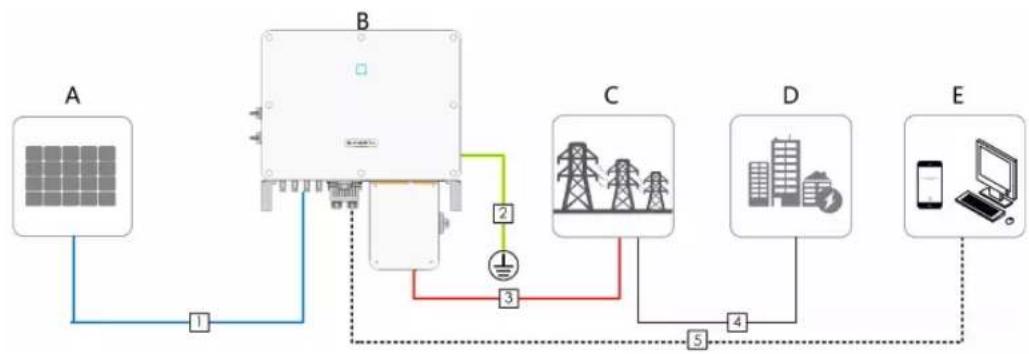
5.3 Electrical Connection Overview
Electrical connection in the PV system includes additional grounding connection, AC connection, and PV string connection.
flowchart
graph TD
    A[" Solar Panel A "] -->|1| B[" Power Transmission Unit B "]
    B -->|2| C[" Grid Tower C "]
    B -->|3| D[" Grid Tower D "]
    C -->|4| E[" Mobile Device E "]
    D -->|5| E
    E -->|6| B
| Item | Designation |
| A | PV string |
| B Inverter | |
| C Grid | |
| D Load | |
| E | Monitoring device |
table 5-1 Cable requirements
| No. Cable | Type | Specification | ||
| Cable Diameter (mm) | Cross-sectional area | |||
| 1 DC cable | PV cable complying with 1,500V standard | 6~9 12~10AWG | ||
| 2 | Additional Grounding cable | Outdoor single-core copper wire cable | / | The same as that of the PE wire in the AC cable |
| 3-4 AC cable | Outdoor multi-core copper or aluminium cable | / | L1,L2,L3,N wire (SG36CX-US): 6~2/0AWG | |
| L1,L2,L3,N wire (SG60CX-US): 5~2/0AWG | ||||
| PE wire: refer to "table 5-2 PE Wire Requirements" | ||||
| 5 | Communi-cation cable | Shielded twisted pair (terminal block) | 4.5~18 | 26~20AWG |
| CAT-5 Ethernet cable (RJ45) | / | |||
table 5-2 PE Wire Requirements
| Item | Recommended PE wire cross section range |
| SG36CX-US/SG60CX-US | 6AWG-4AWG |
5.4 Additional Grounding Connection
! DANGER
Electric shock!
- There are large currents during the inverter's operation. If the inverter is powered on and put into operation without being grounded, it may lead to electric shock hazards or failures of major protective functions such as surge protection. Therefore, before powering on the inverter, make sure it has been reliably grounded; otherwise, damages caused therefrom will not be covered by warranty.
- When performing electrical connections of the inverter, give the highest priority to grounding. Be sure to carry out the grounding connection first.
! WARNING
Since the inverter is a transformerless inverter, neither the negative pole nor the positive pole of the PV string can be grounded. Otherwise, the inverter will not operate normally. Connect the additional grounding terminal to the protective grounding point before AC cable connection, PV cable connection, and communication cable connection. The ground connection of this additional grounding terminal cannot replace the connection of the PE terminal of the AC cable. Make sure thoes terminals are both grounded reliably.
5.4.1 Additional Grounding Requirements
All non-current carrying metal parts and device enclosures in the PV power system should be grounded, for example, brackets of PV modules and inverter enclosure.
When there is only one inverter in the PV system, connect the additional grounding cable to a nearby grounding point.
When there are multiple inverters in the PV system, connect grounding points of all inverters and the PV array frames to the equipotential cable (according to the onsite conditions) to implement an equipotential connection.
5.4.2 Connection Procedure
Step 1 Prepare the cable and OT/DT terminal.
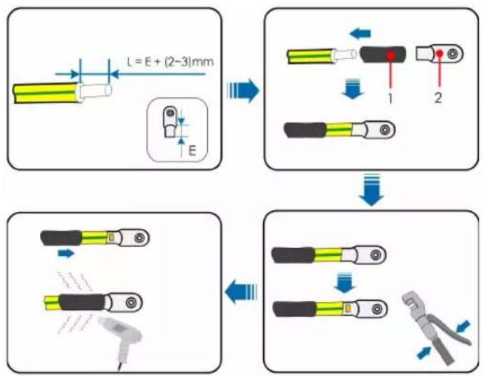
flowchart
graph TD
    A["Component 1: L = E + (2~3)mm"] --> B["Step 1"]
    B --> C["Step 2"]
    C --> D["Step 3"]
    D --> E["Step 4"]
    E --> F["Final Step"]

    subgraph Component 2
        G["Component 2: L = E + (2~3)mm"] --> H["Arrow to E"]
        H --> I["Arrow to E"]
        I --> J["Arrow to E"]
    end

    subgraph Component 3
        K["Component 3: L = E + (2~3)mm"] --> L["Arrow to E"]
        L --> M["Arrow to E"]
        M --> N["Arrow to E"]
        N --> O["Arrow to E"]
    end

    subgraph Component 4
        P["Component 4: L = E + (2~3)mm"] --> Q["Arrow to E"]
        Q --> R["Arrow to E"]
        R --> S["Arrow to E"]
        S --> T["Arrow to E"]
        T --> U["Arrow to E"]
        U --> V["Arrow to E"]
    end
1: Heat shrink tubing 2 : OT/DT terminal
Step 2 Remove the screw on the grounding terminal and fasten the cable with a screwdriver.
text_image
SLP48074 M6 4.2-4.5N·mStep 3 Apply paint to the grounding terminal to ensure corrosion resistance.
-- End

The grounding screws have been anchored to the side of the inverter before delivery, and do not need to be prepared.
There are two grounding terminals. Use at least one of them to ground the inverter.
5.5 AC Cable Connection
5.5.1 AC Side Requirements
Before connecting the inverter to the grid, ensure the grid voltage and frequency comply with requirements, for which, refer to "10.1 Technical Data". Otherwise, contact the electric power company for help.

Connect the inverter to the grid only after getting an approval from the local electric power company.
Multiple Inverters in parallel Connection
If multiple inverters are connected in parallel to the grid, ensure that the total number of parallel inverters does not exceed 30. Otherwise, please contact SUNGROW for technical approval.
MV Transformer
The MV transformer used together with the inverter should meet the following requirements:
- The transformer may be a distribution transformer, and it must be designed for the typical cyclical loads of a PV system (load in the day and no load at night).
- The transformer may be of the liquid-immersed type or dry type, and shield winding is not necessary.
- The line-to-line voltage on the LV side of the transformer should endure the output voltage of inverter. When the transformer is connected to the IT grid, to-ground withstanding voltage of the LV winding of the transformer, the AC cables, and the secondary equipment (including the relay protection device, detection & measuring device, and other related auxiliary devices) should not be lower than 1,100V.
- The line-to-line voltage on the MV side of transformer should comply with local power grid voltage.
- A transformer with a tap changer on the MV side is recommended in order to keep consistent with the grid voltage.
- Transformer with a short-circuit impedance of 6% (permissible tolerance: ±10%) is recommended.
- The voltage drop of system cable is no more than 3% .
- The DC component that the transformer can withstand is 1% of the fundamental current at rated power.
- For thermal rating, the load curve of the transformer and environment conditions should be taken into account.
- The apparent power of the inverter should never exceed the power of the transformer. The maximum AC current of all inverters connected in parallel must be taken into account. If more than 30 inverters are connected to the grid, contact SUNGROW.
- The transformer must be protected against overloading and short circuit.
- The transformer is an important part of a grid-connected PV generation system. The faults tolerance capacity of the transformer should be taken into account at all times. The faults include: system short circuit, grounding fault, voltage drop, etc.
• Take ambient temperature, relative humidity, altitude, air quality, and other environmental conditions into account when selecting and installing the transformer.
5.5.2 Requirements for OT/DT Terminal
OT/DT terminals (not included in the delivery scope) are required for fixing AC cables to the terminal block. Purchase the OT/DT terminals according to the following requirements.
- Specification: M8;
- Dimensions: a ≤ 30mm / 8.4mm ≤ b ≤ 10.5mm / c ≤ 16mm
text_image
a b cfigure 5-2 Dimensions of Terminal
5.5.3 Aluminium Cable Requirements
If an aluminium cable is selected, use a copper to aluminium adapter terminal to avoid direct contact between the copper bar and the aluminium cable.
text_image
Aluminium adapter terminal Flange nut Aluminium cablefigure 5-3 Aluminium cable terminal connection sequence
NOTICE
Ensure that the selected terminal can directly contact with the copper bar. If there are any problems, contact the manufacturer of terminal.
Direct contact between the copper bar and the aluminium cable will cause electrochemical corrosion and impair the reliability of electrical connection.
5.5.4 Connection Procedure
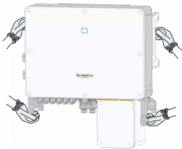
Step 1 Disconnect the AC-side circuit breaker and prevent it from inadvertent reconnection by implementing a lok-out, tag-out(LOTO), in accordance with local regulations.
Step 2 Use an torx wrench to remove the four screws on the AC junction box.
text_image
Technical diagram showing assembly steps of an electronic device with labeled components and directional arrows indicating movement.Step 3 Use a Phillips screwdriver to remove the two screws on the transparent protective cover.
text_image
Diagram illustrating the assembly process of an electrical enclosure, showing component insertion and disassembly steps.Step 4 Use a allen wrench to remove the screw on the bottom of the AC junction box.
text_image
Technical diagram showing assembly of an electronic device with labeled parts and a magnified view of the internal components.Step 5 Strip the protection layer and insulation layer by specific length, as described in the Figure below.
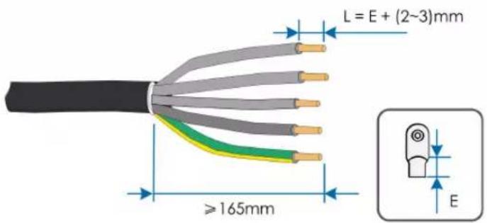
text_image
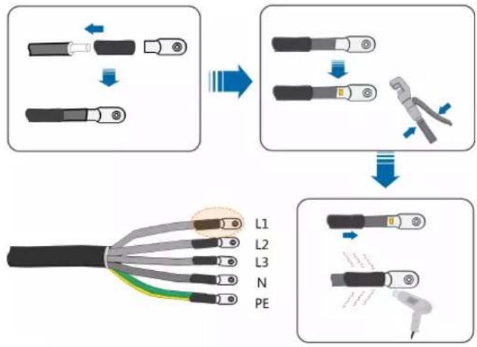
L = E + (2~3)mm ≥165mm EStep 6 Make the cable and crimp OT terminal.
flowchart
graph TD
    A["Disassembly"] --> B["Assembly"]
    B --> C["Repairing"]
    C --> D["Final Assembly"]
    subgraph Initial
        A1["Disassembly"]
        A2["Assembly"]
        A3["Repairing"]
    end
    subgraph Final
        B1["Assembly"]
        B2["Repairing"]
        B3["Final Assembly"]
    end
Step 7 Secure the cable to corresponding terminals.
NOTICE
Observe the terminal layout on the block. Do not connect the phase wires to "PE" terminal or PE wire to "N" terminal. Otherwise, unrecoverable damage to the inverter will occur.
Ensure that the depth L of the socket used is not less than 18mm.

text_image
Technical diagram showing a mechanical assembly with labeled component 'L' and magnified detail viewStep 8 Secure the transparent protective cover, and secure it with Phillips screwdriver.
text_image
Diagram showing assembly steps of an electronic device with labeled components and a magnified view of the internal structure.Step 9 Secure the cover of the AC junction box, and secure it with torx wrench.
text_image
Technical diagram showing assembly steps of a device with labeled components and dimensions-- End
5.6 DC Cable Connection
! DANGER
Electric shock!
The PV array will generate lethal high voltage once exposed to sunlight.
! WARNING
Make sure the PV array is well insulated to ground before connecting it to the inverter.
During the installation and operation of the inverter, please ensure that the positive or negative polarities of PV strings do not short-circuit to the ground. Otherwise, an AC or DC short-circuit may occur, resulting in equipment damage. The damage caused by this is not covered by the warranty.
NOTICE
There is a risk of inverter damage! The following requirements should be met. Failure to do so will void guarantee and warranty claims.
- Make sure the maximum voltage of each string is always less than 1,000 V.
• The MPPT operating voltage range is 200 to 1,000V. - Make sure the maximum short circuit current on the DC side is within the permissible range.
5.6.1 PV Input Configuration
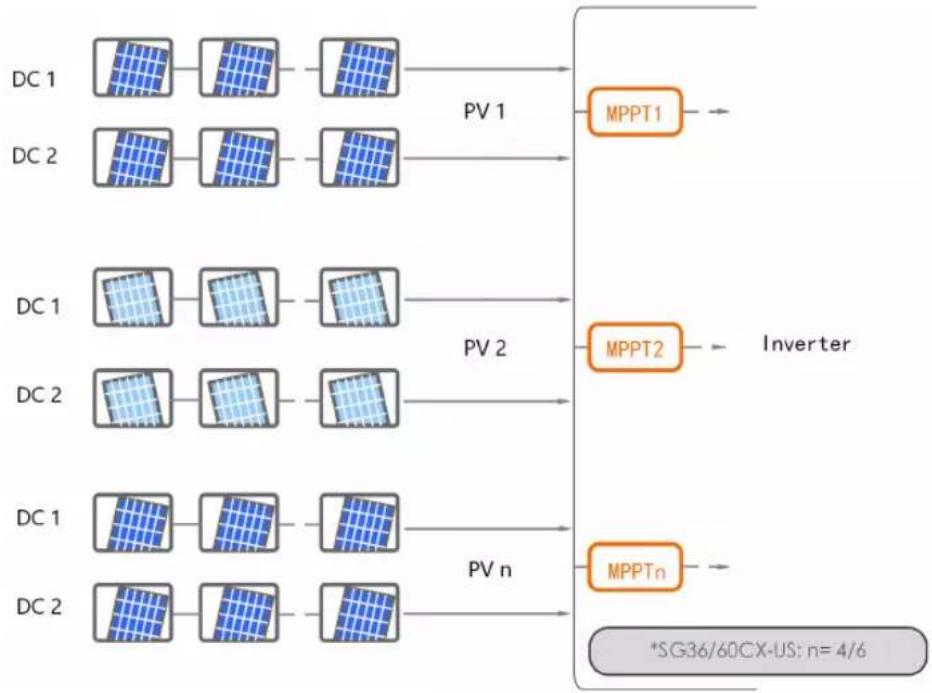
As shown in the Figure below, the inverter is provided with multiple PV inputs: PV inputs 1\~n (SG36CX-US/SG60CX-US: n=8/12); and each PV input is designed with an MPP tracker.
Each PV input operates independently and has its own MPPT. In this way, string structures of each PV input may differ from each other, including PV module type, number of PV modules in each string, angle of tilt, and installation orientation.
Each PV input area includes two DC inputs DC1 and DC2. For the best use of DC power, DC1 and DC2 should be the same in PV string structure, including the type, number, tilt, and orientation of the PV modules.
flowchart
graph LR
    subgraph DC_1
        A1["Grid"] --> B1["Grid"]
        B1 --> C1["Grid"]
        C1 --> D1["Inverter"]
    end
    subgraph DC_2
        A2["Grid"] --> B2["Grid"]
        B2 --> C2["Grid"]
        C2 --> D2["Inverter"]
    end
    subgraph DC_1
        A3["Grid"] --> B3["Grid"]
        B3 --> C3["Grid"]
        C3 --> D3["Inverter"]
    end
    subgraph DC_2
        A4["Grid"] --> B4["Grid"]
        B4 --> C4["Grid"]
        C4 --> D4["Inverter"]
    end
    D1 --> E1["MPPT1"]
    D2 --> E2["MPPT2"]
    D3 --> E3["MPPTn"]
    D4 --> E4["*SG36/60CX-US: n= 4/6"]
Type Open circuit voltage limit
| SG36CX-US | 1000V |
| SG60CX-US | 1000V |
5.6.2 Connection Procedure
SUNGROW provides corresponding plug connectors in the scope of delivery for quick connection of PV inputs.
DC cables should be connected to the inverter via PV connectors which are included in the scope of delivery.

To ensure NEMA Type 4X protection, use only the supplied connector or the connector with the same ingress of protection.
! DANGER
High voltage may be present in the inverter!
- Ensure all cables are voltage-free before performing electrical operations.
- Do not connect the AC circuit breaker before finishing electrical connection.
CAUTION
- Use MC4 DC terminals if the maximum input voltage is no more than 1,000V.
- Use MC4 DC terminals if the maximum input voltage is greater than 1,000V. To purchase the MC4 DC terminals, contact SUNGROW.
- Select appropriate DC terminals as required above. Otherwise, SUNGROW shall be held no liability for the damage caused.
Step 1 Strip the insulation from each DC cable by 7mm.
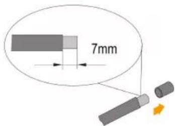
text_image
7mmStep 2 Assemble the cable ends with the crimping pliers.
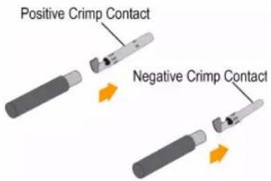
text_image
Positive Crimp Contact Negative Crimp ContactStep 3 Lead the cable through cable gland, and insert into the insulator until it snaps into place. Gently pull the cable backward to ensure firm connection. Tighten the cable gland and the insulator (torque 2.5 N·m to 3 N·m).
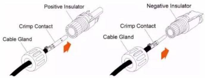
text_image
Positive Insulator Crimp Contact Cable Gland Negative Insulator Crimp Contact Cable GlandStep 4 Check for correct polarity.
NOTICE
The inverter will not function properly if any PV polarity is reversed.
-- End
5.6.3 Installing the PV Connectors
Step 1 Rotate all the DC switches to "OFF" position.
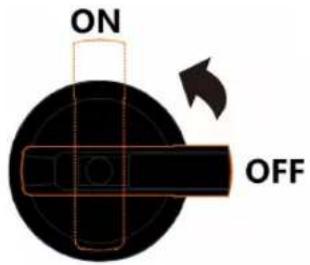
text_image
ON OFF
Skip performing step1 when the actual device is not equipped with DC switches.
Step 2 Check the cable connection of the PV string for correct polarity and ensure that the open circuit voltage in any case does not exceed the inverter input limit of 1,000V.
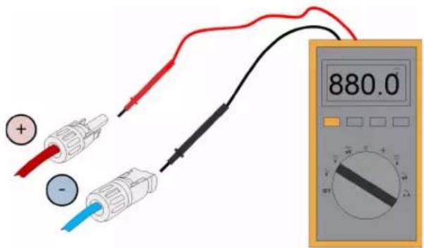
text_image
880.0Step 3 Connect the PV connectors to corresponding terminals until there is an audible click.
NOTICE
Check the positive and negative polarity of the PV strings, and connect the PV connectors to corresponding terminals only after ensuring correct polarity.
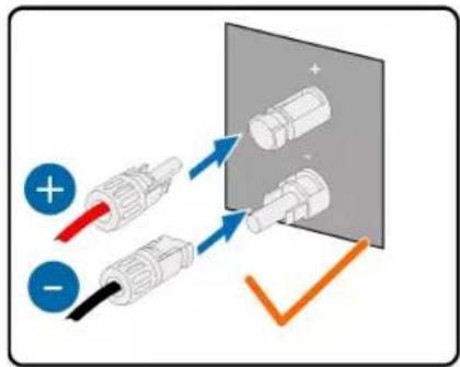
text_image
Diagram showing three connected electrical connectors with positive and negative polarity indicators, alongside a magnified view of cylindrical components.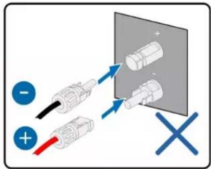
text_image
Diagram showing cable installation with positive and negative terminals, including a magnified view of connected components.Arc or contactor over temperature may occur if the PV connectors are not firmly in place, and SUNGROW shall not be held liable for any damage caused.
Step 4 Follow the foregoing steps to connect PV connectors of other PV strings.
Step 5 Seal the unused PV terminals with the terminal caps.
-- End
NOTICE
• After the PV string is connected to the input terminal on the inverter, please turn on the corresponding DC switch.
- Only when the DC switch is set to "NO", the DC Type II is able to provide effective protection against electrical surges.
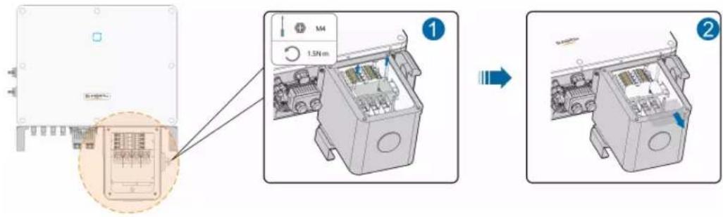
5.7 Communication Junction Box
5.7.1 Remove the Junction Box
Step 1 Squeeze both sides of the junction box and then pull it out to remove it.
text_image
Diagram showing internal components of an electronic device with labeled parts and directional arrows indicating assembly or process.-- End
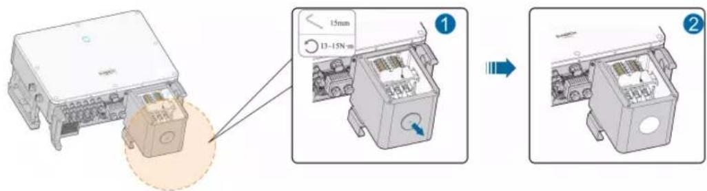
5.7.2 Install the Junction Box
Step 1 Align the junction box with the corresponding port and push it into the port to reassemble junction box.
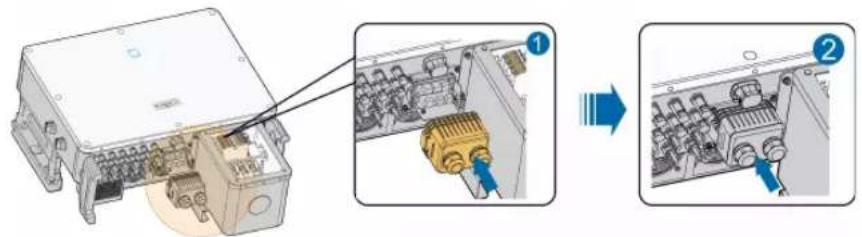
text_image
Technical diagram showing assembly of an electronic device with labeled components and directional arrows indicating process steps.-- End
5.8 Communication Wiring Board
The communication board of the inverter includes two layers. The upper layer communication board mainly includes RS485 communication interfaces while the lower layer communication board mainly includes DI/DO interface and DRM interface.
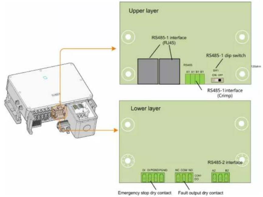
text_image
Upper layer RS485-1 interface (RJ45) RS485-1 dip switch A1 A1 B1 B1 SWI ON OFF RS485-1interface (Crimp) Lower layer RS485-2 interface DX DiPGNDPGND NC COM NO COM DO A2 B2 Emergency stop dry contact Fault output dry contact5.9 RS485 Communication
5.9.1 Interface Description
As shown in the Figure below, the inverter is equipped with three RS485 communication interfaces and one dip switch.
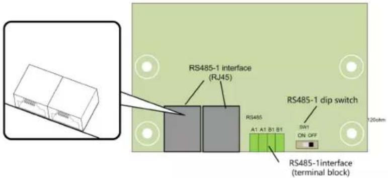
text_image
RS485-1 interface (RJ45) RS485-1 dip switch A1 A1 B1 B1 SW1 ON OFF RS485-1interface (terminal block)All three interfaces can be connected to a data acquisition device (Data Logger), to achieve data exchange with PC or other monitoring devices.
The RS485-1 crimp and the RJ45 interface can be applied to applications where multiple inverters communicate in a daisy-chain form.
A 120Ω resistor can be connected in parallel between RS485-1 A/B pins by configuring the dip switch.
NOTICE
RS485-1 crimp interface and RJ45 interface serve as the same function with different wiring manner.
5.9.2 RS485 Communication System
! WARNING
Either Sunspec or SG Modbus is available, but the two communication protocols cannot be adopted at the same time.
Single-inverter communication system
In case of a single inverter, communication cable connection requires only one RS485 cable.
flowchart
graph TD
    A["Inverter"] --> B["RS485"]
    B --> C["120ohm ON OFF SW1"]
    B --> D["OUT"]
    B --> E["Data Logger"]
    E --> F["PC"]
Multi-inverter communication system
In case of multiple inverters, all the inverters can be connected via RS485 cables in the daisy chain manner.
flowchart
graph TD
    subgraph RJ45
        A1A1B1B1["Terminal Block A1 A1 B1 B1"]
        B1A1B1B1 --> C1Inverter1["Inverter 1 OUT IN"]
        B1A1B1B1 --> D1Inverter2["(N-1) OUT IN"]
        B1A1B1B1 --> E1InverterN["Inverter N OUT"]
    end
    subgraph RJ45
        A1A1B1B1b1["Terminal Block A1 A1 B1 B1"]
        B1A1B1B1b1 --> C1Inverter2b["Inverter 2"]
        B1A1B1B1b1 --> D1InverterNb["Inverter N OUT"]
    end
    subgraph RJ45
        A1A1B1B1b2["Terminal Block A1 A1 B1 B1"]
        B1A1B1B1b2 --> C1Inverter3["Inverter 3"]
        B1A1B1B1b2 --> D1InverterNb["Inverter N OUT"]
    end
    subgraph Inverter_II
        Inverter_IIb["Monitoring Station"] --> DataLogger["Data Logger"]
    end
When more than 15 inverters are connected on the same daisy chain, the inverters on two ends of the chain should be equipped with terminal resistors of 120 to ensure communication quality by configuring the dip switch (SW1), and the shielding layer of the communication cable should be single-point grounded.
flowchart
graph TD
    A["Inverter 1"] -->|OUT| B["Monitoring station"]
    C["Inverter 2~(N-1)"] -->|OUT| B
    D["Inverter N"] -->|OUT| B
    B --> E["Data Logger"]
    E --> F["SW1"]
    style A fill:#f9f,stroke:#333
    style C fill:#f9f,stroke:#333
    style D fill:#f9f,stroke:#333
    style B fill:#ccf,stroke:#333
    style E fill:#cfc,stroke:#333
figure 5-4 Configuration of dip switch (N≥15)
The length of the RS485 cable and twisted pair cable should be no longer than 1,200m.
If multiple inverters are connected to the data logger, the number of permissible daisy chains and the number of devices allowed to be connected should meet the requirements (refer to the user manual for the data logger).
5.9.3 Connection Procedure(Crimp)
RS485 communication cables should be shielded twisted pair cables or shielded twisted pair Ethernet cables.
twisted pair Ethernet cables. There are three communication terminals, and the silkscreen marks are COM1/COM2/COM3. Please choose according to the actual situation.
Step 1 Remove the communication junction box, see "5.7.1 Remove the Junction Box".
Step 2 Strip the protection layer and insulation layer by appropriate length.

text_image
7 mm 20 mmStep 3 Loosen the swivel nut of the junction box and select an appropriate seal according to cable outer diameter. Lead the cable through the swivel nut, seal, and junction box successively.
text_image
Diagram illustrating the assembly of a connector with labeled parts and directional arrows indicating process steps.| Outer diameter D(mm) | Seal |
| 4.5~6 | c |
| 6~12 a+b | |
| 12~18 b |
text_image
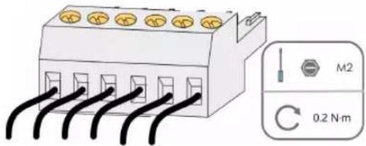
M2 0.2 N·mStep 4 Secure the cable to the terminal base.
Step 5 Insert the terminal base into the corresponding terminal.
table 5-3 Terminal definition
| No Definition |
| 1 RS485 A+ |
| 2 RS485 A+ |
| 3 RS485 B- |
| 4 RS485 B- |
Step 6 If other wiring operations need to be performed on the communication board, finish the wiring operations before performing the following steps. If otherwise, continue to perform the following steps.
Step 7 Install the junction box, see "5.7.2 Install the Junction Box".
Step 8 Pull the cable gently to make sure it is secured, tighten the swivel nut clockwise.
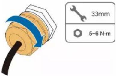
text_image
33mm 5-6 N·m-- End
5.9.4 Connection Procedure (RJ45 Ethernet Port)
Step 1 Remove the communication junction box, see "5.7.1 Remove the Junction Box".
Step 2 Loosen the swivel nut of the junction box and select an appropriate seal according to cable outer diameter. Lead the cable through the swivel nut, seal, and junction box successively.
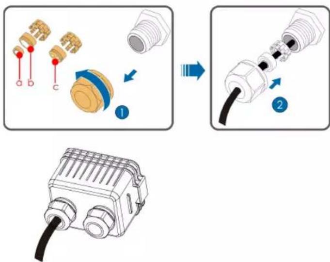
text_image
Diagram illustrating the assembly process of a connector with labeled parts and directional arrows indicating assembly steps.| Outer diameter D(mm) | Seal |
| 4.5~6 | c |
| 6~12 a+b | |
| 12~18 b |
Step 3 Strip the insulation layer of the Ethernet cable with a wire stripper, and insert the signal wires to the RJ45 connector. Crimp the RJ45 connector with a crimping tool.
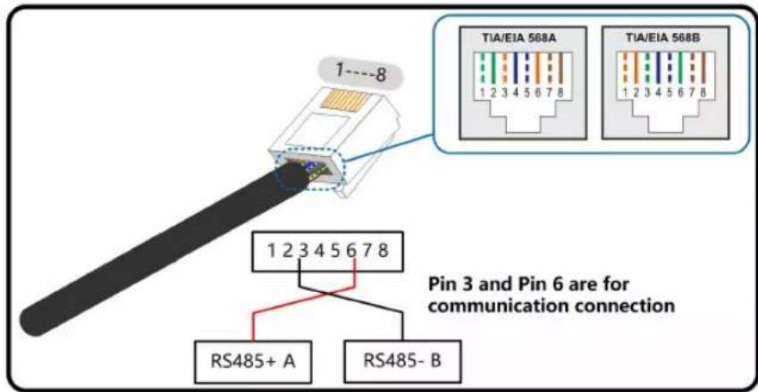
text_image
1---8 TIA/EIA 568A 1 2 3 4 5 6 7 8 TIA/EIA 568B 1 2 3 4 5 6 7 8 Pin 3 and Pin 6 are for communication connection 1 2 3 4 5 6 7 8 RS485+ A RS485- BStep 4 Insert the RJ45 connector to the RJ45 jack.
natural_image
Diagram showing two Ethernet connectors with a blue arrow indicating transformation (no text or symbols)Step 5 If other wiring operations need to be performed on the communication board, finish the wiring operations before performing the following steps. If otherwise, continue to perform the following steps.
Step 6 Install the junction box, see "5.7.2 Install the Junction Box".
Step 7 Pull the cable gently to make sure it is secured, tighten the swivel nut clockwise.
text_image
33mm 5-6 N·m-- End
5.10 Dry Contact Connection
NOTICE
Dry contact cables require a cross section of 18AWG\~16AWG.
The connection procedure of the dry contact is the same as that of the RS485 terminal block.
5.10.1 Dry Contact Function
The configuration circuit board is provided with fault output dry contact and emergency shutdown dry contact, as shown in the Figure below.
Connection method of the dry contacts is similar to that of the RS485 terminal block.
text_image
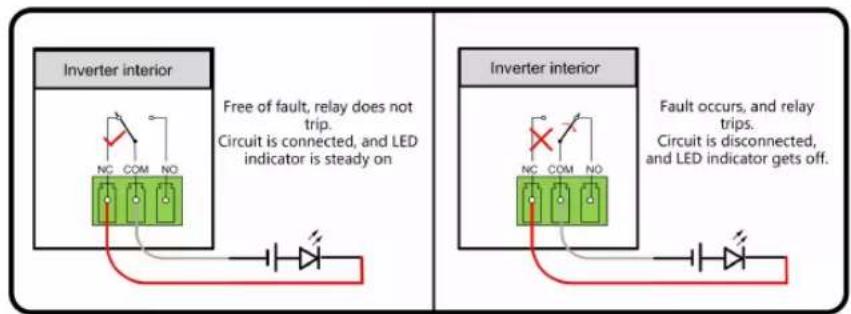
Lower layer DI DIPGNDPGND NC COM NO CON1 DO A2 B2 RS485-2 interface Emergency stop dry contact Fault output dry contactDO terminal (fault output dry contact): The relay can be set to fault alarm output, and user can configure it to be a normally open contact (COM & NO) or a normally closed contact (COM & NC).
The relay is initially at the NC terminal, and it will trip to another contact when a fault occurs. When alarm occurs, signal status change will be not be triggered..
Use LED indicators or other equipment to indicate whether the inverter is in the faulty state.
The following Figures show the typical applications of normal open contact and normally closed contact:
text_image
Inverter interior Free of fault, relay does not trip. Circuit is disconnected, and LED indicator is off Inverter interior Fault occurs, relay trips. Circuit is connected, and LED indicator gets onfigure 5-5 Normal open contact
text_image
Inverter interior Free of fault, relay does not trip. Circuit is connected, and LED indicator is steady on Inverter interior Fault occurs, and relay trips. Circuit is disconnected, and LED indicator gets off.figure 5-6 Normal close contact
Devices connected to the relay should comply with related requirements:
| AC-Side Requirements DC-Side Requirements | |
| Max. voltage: 250Vac | Max. voltage: 30Vdc |
| Max. current: 5A | Max. current: 5A |
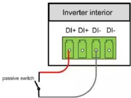
DI terminal (emergency shutdown dry contact): the dry contact can be configured to be an emergency shutdown contact.
When the DI+ contact and DI-contact are shorted by external controlled switch, the inverter will immediately shutdown.

The dry contacts only support passive switch signal input.
The following Figure shows the typical application of local shutdown dry contact.
text_image
Inverter interior DI+ DI+ DI- DI- passive switchfigure 5-7 Local shutdown contact
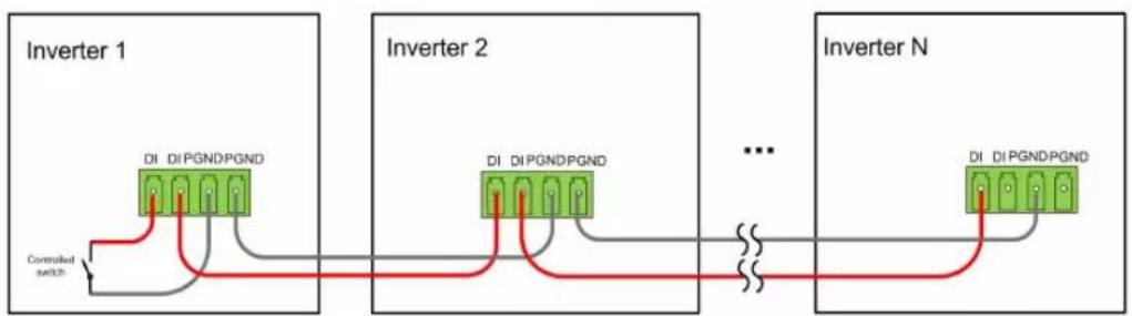
flowchart
graph LR
    subgraph_Inverter_1["Inverter 1"]
        A["DI DI PGNDPGND"] --> B["Controlled switch"]
    end
    subgraph_Inverter_2["Inverter 2"]
        C["DI DI PGNDPGND"] --> D["..."]
    end
    subgraph_Inverter_N["Inverter N"]
        E["DI DI PGNDPGND"] --> F["..."]
    end
figure 5-8 Daisy chain topology
When wiring DI dry contacts, ensure that the maximum wiring distance meet the requirements in "10.2 Wring Distance of DI Dry Contact".
5.10.2 Wiring Procedure
Refer to the wiring of crimp described in Chapter"5.9.3 Connection Procedure(Crimp)" 5.9.3 Connection Procedure
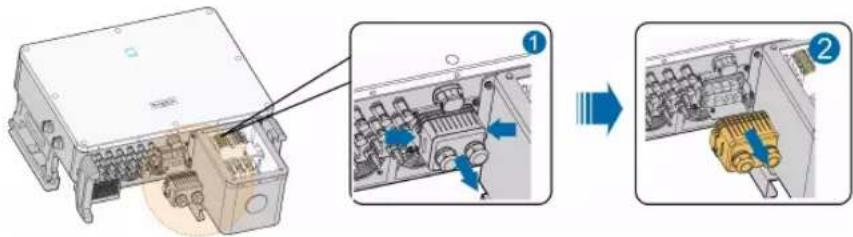
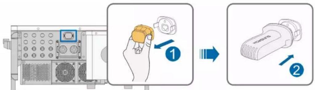
5.11 Communication Module Connection (optional)
Connect the communication module produced by SUNGROW, such as WiNet, Eye, or E-Net to the communication accessory port. After successful connection, information such as power generation and running state of the inverter can be viewed via the App on the phone.
text_image
Diagram illustrating the step-by-step installation of a device, showing hand holding a button and two labeled parts (1 and 2) with arrows indicating process flow.*The image shown here is for reference only. The actual product you receive may differ.
NOTICE
The communication module and the RS485 communication are not available at the same time. Otherwise, communication failure or other problems will occur.

For details on module installation and configuration, refer to the manual delivered with the module.
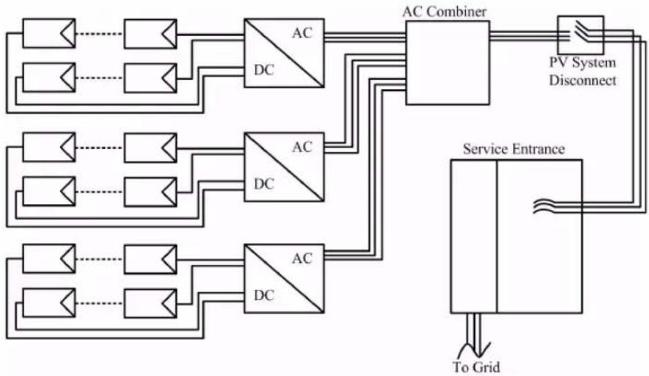
5.12 Module-Level Rapid Shutdown Device Connection (Optional)
5.12.1 Module-Level Rapid Shutdown System Introduction
The Module-Level Rapid Shutdown Devices (RSDs) aim to protect the whole PV system from fire risk via reducing DC voltage to a safe range in a short time.
There is a Power Line Communication (PLC) transmitter inside the SUNGROW inverter, certified with PVRSS, which could send or cease sending ‘keep alive’ signals to RSDs or Smart PV Panels integrated with RSDs according to NEC 690.12 & CA22.2 NO. 330 regulations.
When the SUNGROW inverter is connected to the AC grid, the PLC transmitter receives power via an integrated power supply. Then,
- Once the PLC transmitter is powered, it will send a 'keep alive' signal to RSDs in the PV system.
- Once the inverter is disconnected from the AC grid no matter whether it is grid islanding, the inverter AC is switched off or the general PV system AC is switched off, the PLC transmitter will cease sending 'keep alive' signals. All the RSDs will automatically turn to shutdown mode to limit PV panels output to a very low voltage to keep the whole PV system within a safe DC voltage.
flowchart
graph TD
    A["Input"] --> B["AC Combiner"]
    C["Input"] --> B
    D["Input"] --> E["AC Combiner"]
    F["Input"] --> E
    G["Input"] --> H["AC Combiner"]
    I["Input"] --> H
    J["Input"] --> K["AC Combiner"]
    L["Input"] --> K
    M["Input"] --> N["AC Combiner"]
    O["Input"] --> N
    P["Input"] --> Q["AC Combiner"]
    R["Input"] --> Q
    S["Input"] --> T["AC Combiner"]
    U["Input"] --> T
    V["Input"] --> W["AC Combiner"]
    X["Input"] --> W
    Y["Input"] --> Z["AC Combiner"]
    AA["Input"] --> Z
    AB["Input"] --> AC["AC Combiner"]
    AD["Input"] --> AC
    AE["Input"] --> AF["AC Combiner"]
    AG["Input"] --> AF
    AH["Input"] --> AI["AC Combiner"]
    AJ["Input"] --> AI
    AK["Input"] --> AL["AC Combiner"]
    AM["Input"] --> AL
    AN["Input"] --> AO["AC Combiner"]
    AP["Input"] --> AO
    AQ["Input"] --> AR["AC Combiner"]
    AS["Input"] --> AR
    AT["Service Entrance"] --> AU["To Grid"]
    AU --> AV["Output"]
5.12.2 Module-Level Rapid Shutdown Device Connection
For RSDs connection, please refer to the RSD or Smart PV panel manuals. There is no additional connection for the SUNGROW inverter directly to RSDs. SUNGROW PLC transmitter supports most of the popular RSDs or Smart PV panel brands and models. Confirm with SUNGROW to check the detailed list of RSD brands and models supported before beginning the PV system design.
6 Commissioning
6.1 Inspection before Commissioning
Check the following items before starting the inverter:
- The inverter DC switch and external circuit breaker are disconnected.
- The inverter should be accessible for operation, maintenance and service.
- Nothing is left on the top of the inverter.
- The inverter is correctly connected to external devices, and the cables are routed in a safe place and protected against mechanical damage.
- The selection of the AC circuit breaker is in accordance with this manual and all applicable local standards.
- All unused terminals at the bottom of the inverter are properly sealed.
- Warning signs & labels are suitably affixed and secured to the inverter.
6.2 Commissioning Procedure
If all of the items mentioned above meet the requirements, proceed as follows to start up the inverter for the first time.
Step 1 Rotate the DC and AC switch of the inverter to the "ON" position.
Step 2 Connect the AC switch (if applicable) between the inverter and the grid.
Step 3 Connect the DC switch (if applicable) between the inverter and the PV string.
Step 4 Set initial protection parameters in the iSolarCloud App via Bluetooth. For details, please refer to "7.3.2 Login Steps". If the irradiation and grid conditions meet requirements, the inverter will advance through its initialization procedure and begin operation.
Step 5 Observe the LED indicator to ensure that the inverter operates normally. (Refer to "table 2-1 LED indicator description").
-- End
6.3 Module-Level Rapid Shutdown Commissioning (Optional)
After the RSDs or Smart PV panels are installed, please adhere the Rapid Shutdown Warning Label from the RSD or Smart PV panel package to:
- A visible place on SUNGROW Inverter AC switch box / PV System Disconnect panel/Service Entrance panel etc. when there is only one inverter in the PV system.
- A visible place on PV System Disconnect panel/ Service Entrance panel etc. when there are multiple inverters in the PV system.
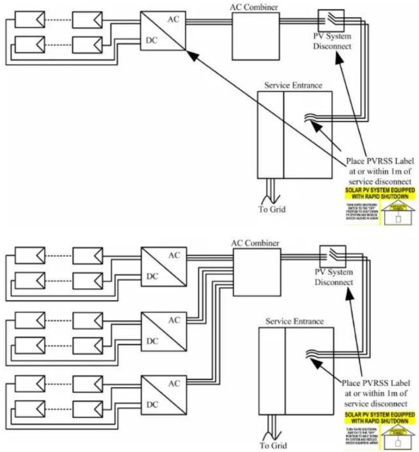
flowchart
graph TD
    A["AC Combiner"] --> B["PV System Disconnect"]
    B --> C["Service Entrance"]
    C --> D["To Grid"]
    D --> E["Place PVRSS Label at or within 1m of service disconnect\nSOLAR PV SYSTEM EQUIPPED WITH RAPID SHUTDOWN"]
    E --> F["To Grid"]
    F --> G["Service Entrance"]
    G --> H["To Grid"]
    H --> I["Place PVRSS Label at or within 1m of service disconnect\nSOLAR PV SYSTEM EQUIPPED WITH RAPID SHUTDOWN"]
    I --> J["To Grid"]
    J --> K["Service Entrance"]
    K --> L["To Grid"]
    L --> M["Service Entrance"]
    M --> N["To Grid"]
    N --> O["Service Entrance"]
    O --> P["To Grid"]
    P --> Q["Service Entrance"]
    Q --> R["To Grid"]
    R --> S["Service Entrance"]
    S --> T["To Grid"]
    T --> U["Service Entrance"]
    U --> V["To Grid"]
    V --> W["Service Entrance"]
    W --> X["To Grid"]
    X --> Y["Service Entrance"]
    Y --> Z["To Grid"]
7 iSolarCloud App
7.1 Brief Introduction
The iSolarCloud App can establish communication connection to the inverter via the Bluetooth, thereby achieving near-end maintenance on the inverter. Users can use the App to view basic information, alarms, and events, set parameters, or download logs, etc.

This manual describes only how to achieve near-end maintenance via the Bluetooth connection. For maintenance through SUNGROW communication device, refer to the related manuals in SUNGROW website
Screenshots in this manual are based on the Android system V2.1.6, and the actual interfaces may differ.
7.2 Download and Install
Method 1
Download and install the App through the following application stores:
- Google Play (Android)
- App store (iOS)
Method 2
Scan the following QR code to download and install the App according to the prompt information.

text_image
QR code with an orange circular logo containing a cloud and sunburst symbol in the center.The App icon appears on the home screen after installation.

7.3 Login
7.3.1 Requirements
The following items should meet requirements:
- The AC or DC side of the inverter is powered-on.
- The smart phone is within 5m of the inverter and there are no obstructions in between.
- The Bluetooth function of the smart phone is enabled.
7.3.2 Login Steps
Step 1 Open the App to enter the login page, tap Local Access at the bottom of the page to go to the next page.
Step 2 Scan the QR code on the side of the inverter for Bluetooth connection. Or tap MANUAL CONNECTION at the bottom of the interface and select Others, the Bluetooth search interface will automatically appear. Select the inverter to be connected according to the serial number on the nameplate on the side of the inverter, or tap scan the QR code on the side of the inverter for Bluetooth connection. The connection is successfully established if the LED indicator blinks blue.
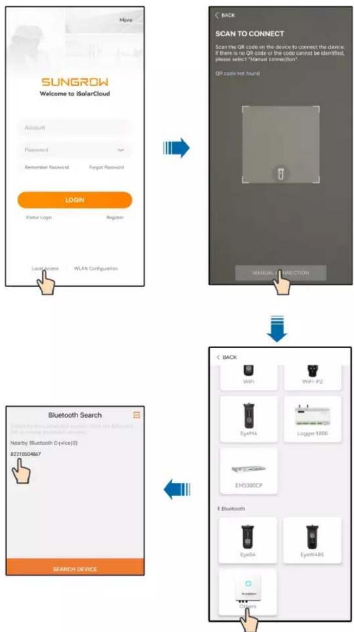
flowchart
graph TD
    A["SUNGROW\nWelcome to iSolarCloud\nAccount\nPassword\nRemember Password\nForgot Password"] --> B["LOGIN\nVisitor Login\nRegister\nLocalAccess\nWLAN Configuration"]
    B --> C["SCAN TO CONNECT\nScan the QR code on the device to connect the device\nif there is no QR code or the code cannot be identified,\nplease select 'Manual connection'。\nQR code not found\nMANUAL Connection"]
    C --> D["Bluetooth Search\nNearby Bluetooth Device(0)\n8221004667\nSEARCH DEVICE"]
    D --> E["Back\nWiFi\nWiFi-P2\nEyeWi4\nLogger 1000\nEMS300CP\nBluetooth\nEyeSi4\nEyeWi4BS\nOther"]
figure 7-1 Bluetooth connection
Step 3 Enter the identity verification screen after the Bluetooth connection is established.

text_image
BACK IDENTITY VERIFICATION ✓ B2210504867 Account user Password ... ✓ Remember Me VERIFICATIONfigure 7-2 Login

The username is "user", and the initial password is "pw1111" which should be changed for the consideration of account security.
To set inverter parameters related to grid protection and grid support, contact SUNGROW to obtain the advanced account and corresponding password.
Step 4 If the inverter is not initialized, you will enter the quick setting screen to initialize protection parameters. After completing the settings on the quick setting screen, click "TURN ON DEVICE" and the device will be initialized. The App will send start instructions and the device will start and operate.
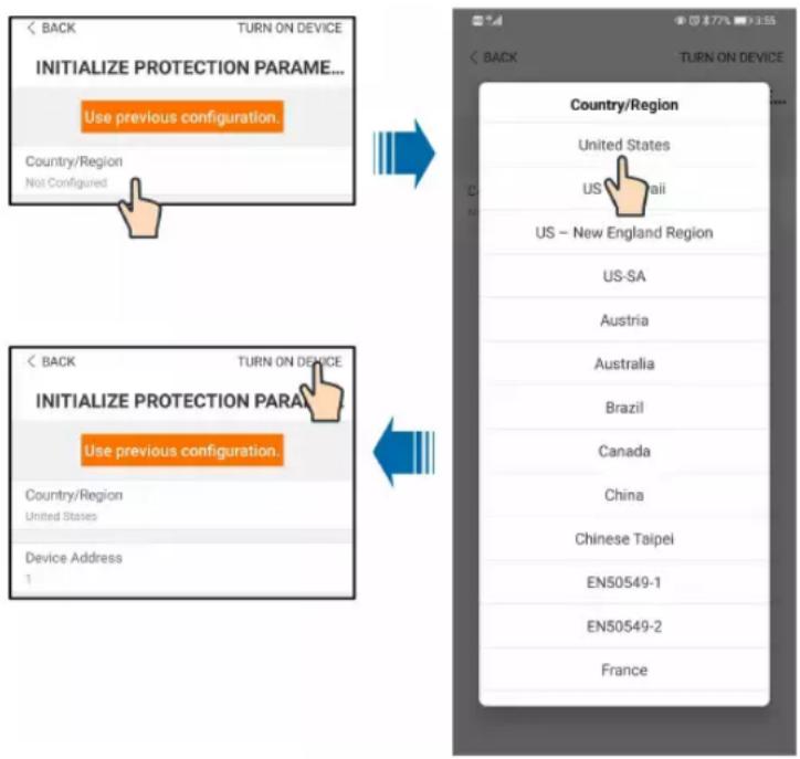
text_image
INITIALIZE PROTECTION PARAME... Use previous configuration Country/Region Not Configured Country/Region United States US - New England Region US-SA Austria Australia Brazil Canada China Chinese Taipei EN50549-1 EN50549-2 Francefigure 7-3 Initialization protection parameter
NOTICE
Reset the grid protection parameters if the country setting is incorrect. Otherwise, faults will occur.
In the US region, conformity to UL 1741 (Third Edition, September 28, 2021) includes compliance with applicable requirements of IEEE 1547-2003 (R2008), IEEE 1547.1-2005 (R2011), California Electric Rule 21, Hawaiian Electric Co. SRD-UL-1741-SA-V1.1 and Supplement SA8-18, UL 1741 Supplement SB and IEEE 1547.1-2020 with the SRDs of IEEE 1547-2018, IEEE 1547a-2020 and Hawaiian Electric Co. SRD-V2.0. While the grid support function evaluated according to IEEE 1547.1-2020, the interoperability is verified with IEEE 2030.5-2018 communication protocol. In Canadian region, conformity to CSA C22.2, No.107.1-16.

Step 5 If the inverter is initialized, the App automatically turns to its home page.
-- End
7.4 Function Overview
The App provides parameter viewing and setting functions, as shown in the following "figure 7-4 App function tree map".
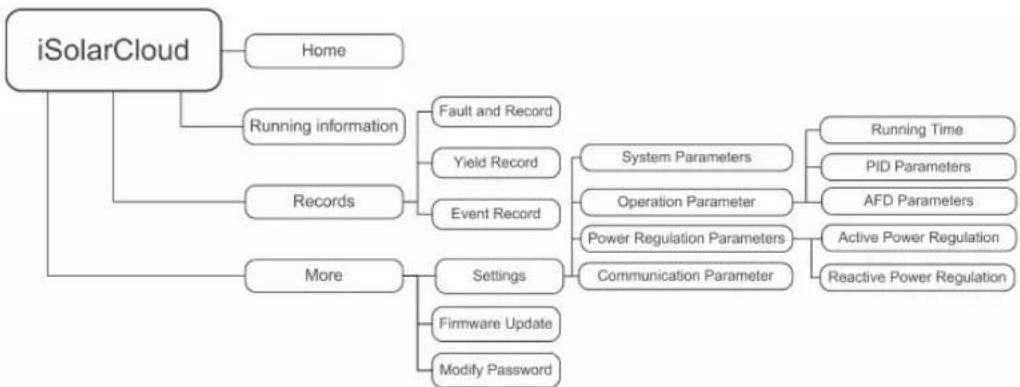
flowchart
graph TD
    A["iSolarCloud"] --> B["Home"]
    A --> C["Records"]
    A --> D["More"]
    C --> E["Fault and Record"]
    C --> F["Yield Record"]
    C --> G["Event Record"]
    D --> H["System Parameters"]
    D --> I["Operation Parameter"]
    D --> J["Power Regulation Parameters"]
    D --> K["Communication Parameter"]
    H --> L["Running Time"]
    H --> M["PID Parameters"]
    H --> N["AFD Parameters"]
    I --> O["Active Power Regulation"]
    I --> P["Reactive Power Regulation"]
    D --> Q["Settings"]
    D --> R["Firmware Update"]
    D --> S["Modify Password"]
figure 7-4 App function tree map
7.5 Home page
After login, the home page is as follows:
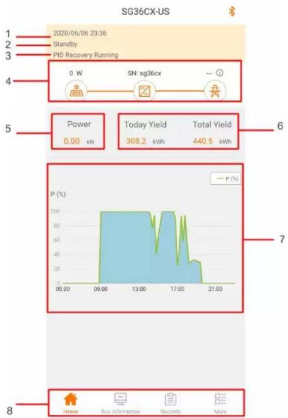
text_image
SG36CX-US 1 2020/06/06 23:36 2 Standby 3 PID Recovery Running 4 0 W SN: sg36cx -- 5 Power 0.00 kw Today Yield 308.2 kWh Total Yield 440.5 kWh 6 7 8 Home Run Information Records Morefigure 7-5 Home page
table 7-1 Home page description
| No. | Designation | Description |
| 1 | Date and time | System date and time of the inverter. |
| 2 | Inverter state | Present operation state of the inverter For details, refer to Tab. 7-2Description of inverter state. |
| 3 | PID function state | Present state of the PID function For details, refer to Tab. 7-3Description of PID function state. |
| 4 | Power flow chart | Display the PV power generation power, feed-in power, etc.The line with an arrow indicates energy flow between connected devices, and the arrow pointing indicates energy flow direction. |
| 5 | Power generation | Daily power yield and accumulative power yield of the inverter. |
| 6 | Real-time power | Output power of the inverter. |
| No. | Designation Description | |
| 7 | Power curve | Curve showing change of power between 5 am and 11 pm every day.(Each point on the curve represents the percentage of present inverter power to rated power) |
| 8 | Navigation bar | Including "Home", "Run information", "Records", and "More". |
table 7-2 Description of inverter state
| State | Description |
| Run | After being energized, inverter tracks the PV arrays' maximum power point (MPP) and converts the DC power into AC power. This is the normal operation mode. |
| shutdown | Inverter is stopped. |
| Key-shutdown | Inverter will shutdown operation by manually selecting “shutdown” via app. To restart the inverter, manually start via app. |
| Standby | Inverter enters standby mode when DC side input is insufficient. In this mode inverter will wait within the standby duration. |
| Initial standby | The inverter is in the initial power-on standby state. |
| Starting | The inverter is initializing and synchronizing with the grid. |
| Warning | Warning information is detected. |
| Derating running | The inverter derates actively due to environmental factors such as temperature. |
| Scheduling running | The inverter runs according to the scheduling instructions received from the monitoring background. |
| Fault | If a fault occurs, inverter will automatically stop operation, and disconnect the AC relay. The fault information will be displayed in the app. Once the fault is removed in recovery time, inverter will automatically resume running. |
table 7-3 Description of PID function state
| State | Description |
| PID recovery running | The inverters perform PID recovery actively. |
| PID abnormality | It is detected that the ISO impedance is abnormal or the PID function cannot work normally after the PID function enabled. |
If the inverter is running abnormally, the alarm or fault icon will be displayed in the lower right corner of the inverter icon in power flow chart. The user can tap this icon to enter the alarm or fault screen to view detailed information and corrective measures.
7.6 Running Information

Tap "Run Information" on the navigation bar to enter the running information screen, as shown in the following Figure.
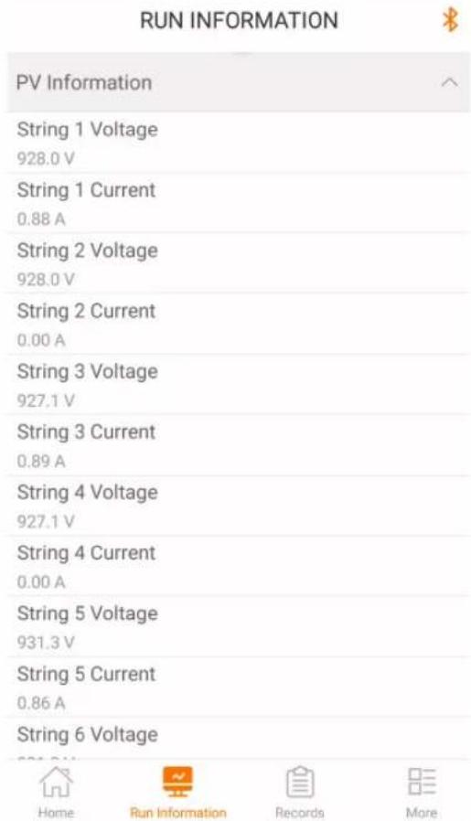
text_image
RUN INFORMATION PV Information String 1 Voltage 928.0 V String 1 Current 0.88 A String 2 Voltage 928.0 V String 2 Current 0.00 A String 3 Voltage 927.1 V String 3 Current 0.89 A String 4 Voltage 927.1 V String 4 Current 0.00 A String 5 Voltage 931.3 V String 5 Current 0.86 A String 6 Voltage Home Run Information Records Morefigure 7-6 Running Information
The run information includes the PV information, inverter information, input and output information.
table 7-4 Run information
| Classification | Parameter | Description |
| PV | String n Voltage The input voltage of the n^th string | |
| Information | String n current The input current of the n^th string | |
| Total On-grid | / | |
| Running Time | ||
| Inverter | Daily On-grid | / |
| Information | Running Time | |
| Negative Voltage to Ground | Inverter DC side negative to ground voltage value | |
| Bus Voltage | Voltage between the positive and negative poles of the DC side of the inverter | |
| Internal Air Temperature | / | |
| Array Insulation Resistance | Insulation resistance value of the input side to the protection ground | |
| Country Information / | ||
| Power Limitation Mode | / | |
| Reactive Power Mode | / | |
| Input | Total DC Power | DC side total input power |
| MPPT x Voltage The | input voltage of the x^th MPPT | |
| MPPT x Current | The input current of the MPPT | |
| Output | Daily Yield / | |
| Monthly Yield | / | |
| Annual Yield | / | |
| Total Active Power | Current active power value of the inverter | |
| Total Reactive Power | Current reactive power value of the inverter | |
| Total Apparent Power | Current apparent power value of the inverter | |
| Total Power Factor | Power factor of the AC side of the inverter | |
| Gird Frenquency Frequency of the AC side of the inverter | ||
| A-B Phase Voltage | Line VoltageB-C Phase Voltage | |
| C-A Phase Voltage | ||
| Phase A Current | Phase CurrentPhase B Current | |
| Phase C Current | ||
7.7 History Record
Tap " Records" on the navigation bar to enter the history record screen, as shown in the following Figure.
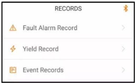
text_image
RECORDS Fault Alarm Record > Yield Record > Event Records >figure 7-7 History record
On "history record" screen, users can check the fault alarm record, yield records and event records.
7.7.1 Fault and Alarm Records
Tap "△" to view fault alarm records, as shown in the following Figure.
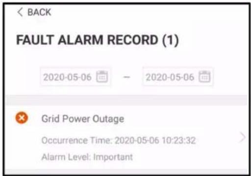
text_image
BACK FAULT ALARM RECORD (1) 2020-05-06 — 2020-05-06 Grid Power Outage Occurrence Time: 2020-05-06 10:23:32 Alarm Level: Importantfigure 7-8 Fault and alarm records

- Click " " to select a time segment and view corresponding records.
• The inverter can record up to 400 latest entries.
Select one of the records on the list and click the record, to view the detailed fault info as shown in following Figure.
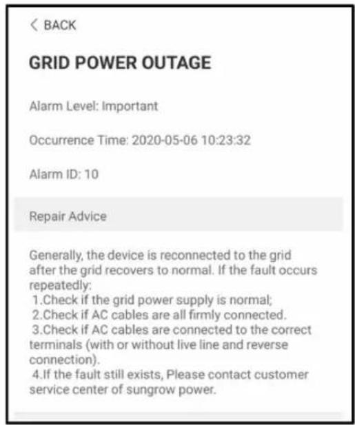
text_image
< BACK GRID POWER OUTAGE Alarm Level: Important Occurrence Time: 2020-05-06 10:23:32 Alarm ID: 10 Repair Advice Generally, the device is reconnected to the grid after the grid recovers to normal. If the fault occurs repeatedly: 1.Check if the grid power supply is normal; 2.Check if AC cables are all firmly connected. 3.Check if AC cables are connected to the correct terminals (with or without live line and reverse connection). 4.If the fault still exists, Please contact customer service center of sungrow power.figure 7-9 Detailed fault and alarm information
7.7.2 Yields Records
User can view various energy records: power curve, daily energy histogram, monthly energy histogram, and annual energy histogram.
table 7-5 Explanation of power yields records
| Parameter | Description |
| Power curve | Show the power output from 5 am to 11 pm in a single day. Each point in the curve is the percentage of present power and nominal power. |
| Daily energy histogram | Shows the power output every day in the present month. |
| Monthly energy histogram | Shows the power output every month in a year. |
| Annual energy histogram | Shows the power output every year. |
Click the "Yield Record" to view the power curve page as shown in following Figure.
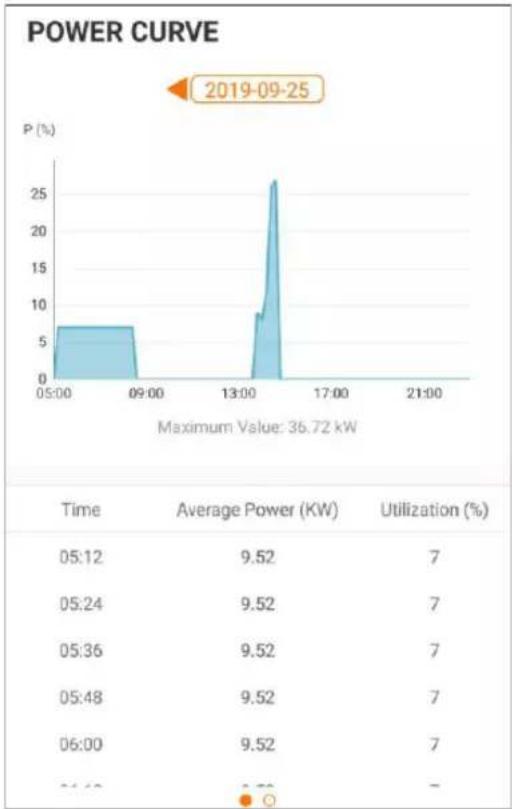
line
| Time | Average Power (KW) | Utilization (%) | | ------ | ------------------ | --------------- | | 05:12 | 9.52 | 7 | | 05:24 | 9.52 | 7 | | 05:36 | 9.52 | 7 | | 05:48 | 9.52 | 7 | | 06:00 | 9.52 | 7 | | 06:12 | - | - |figure 7-10 Power Curve
Tap the time bar on the top of the screen to select a time segment and view the corresponding power curve.
Swipe left to check the power yields histogram.
7.7.3 Event Records
Click "toerview" event record list.

- Click " [REDACTED] " to select a time segment and view corresponding event records.
• The inverter can at most record the latest 400 events.
7.8 More
Tap "More" on the navigation bar to enter the "More" screen, as shown in the following Figure.
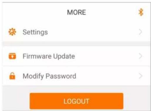
text_image
MORE Settings Firmware Update Modify Password LOGOUTfigure 7-11 More
7.8.1 Parameter Setting
Tap "★" to enter the setting screen, as shown in the following Figure.

text_image
MORE Settings Modify Password LOGOUT BACK SETTINGS System Parameters > Operation Parameters > Power Regulation Parameters > Communication Parameters >figure 7-12 Settings
- System Parameters
Tap "System parameter" to enter the system parameter screen on which boot/shutdown instruction can be sent to the inverter, set the date and time, and information such as ARM software version and MDSP software version can be viewed, as shown in the following Figure.
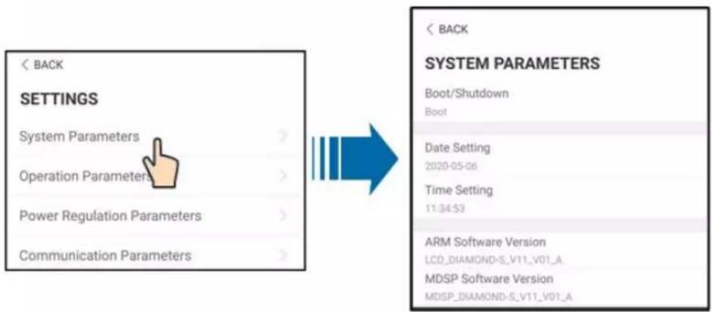
text_image
< BACK SETTINGS System Parameters > Operation Parameters > Power Regulation Parameters > Communication Parameters > BACK SYSTEM PARAMETERS Boot/Shutdown Boot Date Setting 2020-05-06 Time Setting 11:34:53 ARM Software Version LCD_DIAMOND-S_V11_V01_A MDSP Software Version MDSP_DIAMOND-S_V11_V01_Afigure 7-13 System Parameters
• Operation Parameters
Tap" to enter Operation Parameters screen, as shown in the following Figure.
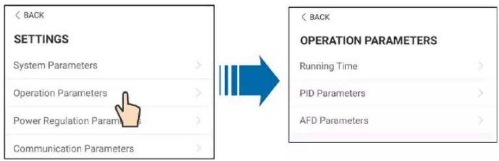
text_image
< BACK SETTINGS System Parameters > Operation Parameters > Power Regulation Parameter > Communication Parameters > < BACK OPERATION PARAMETERS Running Time > PID Parameters > AFD Parameters >figure 7-14 Operation Parameters
- Running Time
Tap"Running Time " to enter Running Time screen on which can set running time and reconnecting time, as shown in the following Figure.
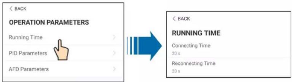
text_image
< BACK OPERATION PARAMETERS Running Time > PID Parameters > AFD Parameters > < BACK RUNNING TIME Connecting Time 20 s Reconnecting Time 20 sfigure 7-15 Running Time
- PID Parameters
Tap"PID Parameters" to enter PID Parameters screen, on which PID recovery function can be enabled or disabled; and PID alarm and PID scheme can be cleared, and PID scheme can be setting as apply negative or apply positive votage, as shown in the following Figure.
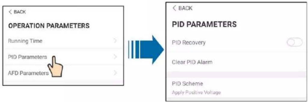
text_image
< BACK OPERATION PARAMETERS Running Time > PID Parameters > AFD Parameters > BACK PID PARAMETERS PID Recovery Clear PID Alarm PID Scheme Apply Positive Voltage BACKfigure 7-16 PID Parameters
- AFCI Parameters
Tap" AFD Parameters" to enter AFCI Parameters screen, on which AFD self-test function and AFCI activation function can be enabled or disabled; and AFD alarm can be cleared, as shown in the following Figure.
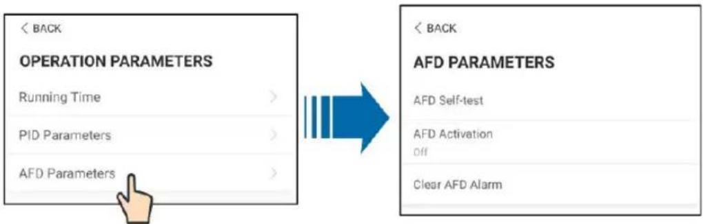
flowchart
graph LR
    A["<<BACK<br>OPERATION PARAMETERS<br>Running Time >"] --> B["<<BACK<br>AFD PARAMETERS<br>AFD Self-test<br>AFD Activation<br>Off"]
    C["<<BACK<br>AFD Parameters<br>AFD Parameters >"] --> B
figure 7-17 AFD Parameters
• Power Regulation Parameters
Tap"Power Regulation Parameters" to enter Power Regulation Parameters screen, on which active power regulation or reactive power regulation can be performed on the inverter, as shown in the following Figure.
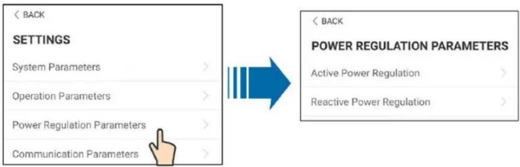
text_image
< BACK SETTINGS System Parameters > Operation Parameters > Power Regulation Parameters > Communication Parameters > < BACK POWER REGULATION PARAMETERS Active Power Regulation > Reactive Power Regulation >figure 7-18 Power Regulation Parameters
table 7-6 Active power regulation
| Parameter | Definition/Setting description | Range |
| Active power soft start after fault | The switch for enabling/disabling the soft start function after a fault occurs. | Enable/Disable |
| Active power soft start time after fault | Time that the soft start takes to ~1200s raise the power from 0 to 100% rated power. | |
| Active power gradient control | Switch for enabling/disabling the active power rate settable function. | Enable/Disable |
| Active power decline gradient | The decline rate of inverter active power per minute. | 3%/min~6000%/min |
| Active power rising gradient | The rise rate of inverter active 3%/min~6000%/min power per minute. | |
| Active power setting persistence | Switch for enabling/disabling the function of saving output limited power. | Enable/Disable |
| Active power limit The switch for limiting output power. | Enable/Disable | |
| Active power limit ratio The ratio of limiting output power to rated power in percentage. | 0%~100% | |
| Shutdown when active power limit to 0% | Switch used to determine whether the inverter is in stop state when the limited power reaches 0. | Enable/Disable |
table 7-7 Reactive power regulation
| Parameter | Definition/Setting description | Range |
| Reactive power generation at night | Switch for enabling/disabling night SVG function. | Enable/Disable |
| Reactive power ratio at night | Reactive power ratio set for the night SVG function. | -100%~0%/0%~100% |
| Reactive power setting persistence | Switch for enabling/disabling the power-off function during reactive power. | Enable/Disable |
| Reactive power regulation mode | — | Off/PF/Qt/Q(P)/Q(U) |
| Reactive power regulation | Switch for enabling/disabling reactive response function. | Enable/Disable |
| Reactive power regulation time | Ends time of reactive response. | 0.1s~600.0s |
| Q(P)Curve | — | Curve A/Curve B/Curve C* |
| QP_P1 | — | 10.0%~100.0% |
| QP_P2 | — | 20.0%~100.0% |
| QP_P3 | — | 20.0%~100.0% |
| QP_K1 | — | Curve A/CurveC:0.800~1.000Curve B: [-0.600~0.600]*-Active Overload Rate/1000 |
| QP_K2 | — | Curve A/Curve C:0.800~1.000Curve B: [-0.600~0.600]*-Active Overload Rate/1000 |
| QP_K3 | — | Curve A/Curve C:0.800~1.000Curve B: [-0.600~0.600]*-Active Overload Rate/1000 |
| QP_EnterVoltage | — | 100.0%~110.0% |
| QP_ExitVoltage | — | 90.0%~100.0% |
| QP_EXitPower | — | 1.0%-20.0% |
| QP_EnableMode | — | Yes/No |
| Q(U)Curve Selection of Q(U) curve. Curve A/Curve B/Curve C* | ||
| QU_V1 Pre-set grid voltage U1 that is reactive according to the grid voltage | 80.0%~100.0% | |
| QU_Q1 Pre-set proportion of reactive power according to the grid voltage U1 | [-60.0%-0]* Overload Rate/1000 | |
| QU_V2 Pre-set grid voltage U2 that is reactive according to the grid voltage. | 80.0%~100.0% | |
| QU_Q2 Pre-set proportion of reactive power according to the grid voltage U2. | [-60.0%-60.0%]* Overload Rate/1000 | |
| QU_V3 Pre-set grid voltage U3 that is reactive according to the grid voltage. | 100.0%~120.0% | |
| QU_Q3 Pre-set proportion of reactive power according to the grid voltage U3. | [-60.0%-60.0%]* Overload Rate/1000 | |
| QU_V4 Pre-set grid voltage U4 that is reactive according to the grid voltage. | 100.0%~120.0% | |
| QU_Q4 Pre-set proportion of reactive power according to the grid voltage U4. | [0-60.0%]* Overload Rate/1000 | |
| QU_EnterPower Pre-set active power point enabled by the Q(U) function. | 20.0%~100.0% | |
| QU_EXitPower Pre-set active power point disabled by the Q (U) function. | 1.0%~20.0% | |
| QU_EnableMode Pre-set unconditional entry and exit Q (U) function. | Yes/No/Yes,Limited by PF | |
| QU_Limited PF Value — | 0-0.95 | |
**Curve C is reserved and consistent with Curve A currently.
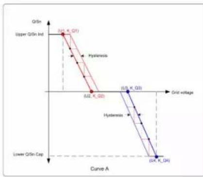
line
| Point Label | GrSn Level | Grid Voltage | |-------------|------------|--------------| | A.U. K_Q2 | 0.2 | 0.2 | | B.U. K_Q3 | 0.2 | 0.4 | | B.U. K_D4 | 0.4 | 0.4 |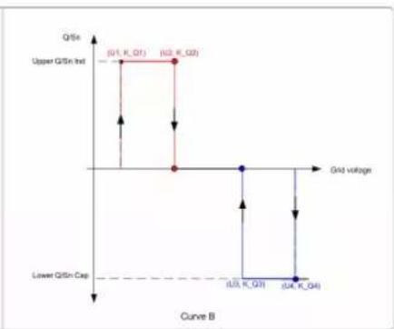
line
| Grid voltage | Q/Si | | :--- | :--- | | (Q1, K_Q1) | Upper Q/Si Int | | (U2, K_Q2) | Upper Q/Si Int | | U3, K_Q3 | Lower Q/Si Cap | | U4, K_Q4 | Lower Q/Si Cap |figure 7-19 Q(U) Curve
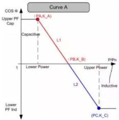
line
| Point Label | PV Power (P/Pn) | Capacitance (COS Φ) | |-------------|-----------------|---------------------| | (PA,K_A) | High | High | | (PB,K_B) | Low | Medium | | (PC,K_C) | Low | Low |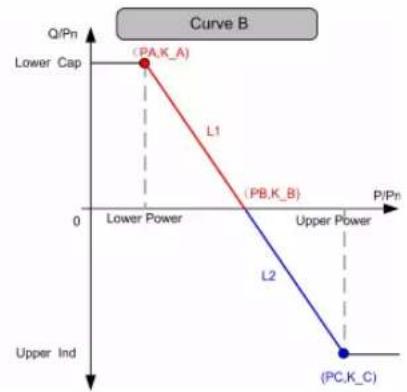
line
| Point | P/Pn | Q/Pn | |-------|------|------| | PA,K_A | 0 | 1 | | PB,K_B | 0 | 0 | | PC,K_C | 0 | 0 |figure 7-20 Q(P) Curve
- Communication Parameters
Tap"Communication Parameters" to enter Communication Parameters screen on which the user can set the device address of inverter, as shown in the following Figure.
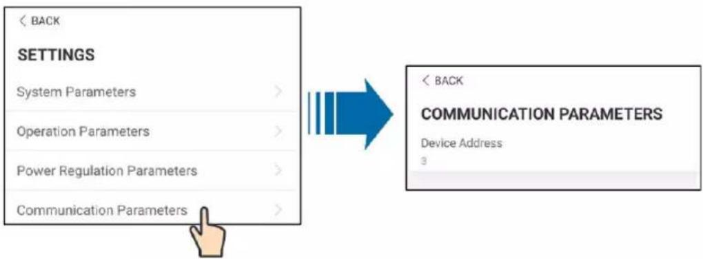
figure 7-21 Communication Parameters
WARNING
Inappropriate parameter settings may cause inverter exception. Only professional personnel can set the foregoing parameters.
7.8.2 Firmware Update
Preparation of firmware update package
Contact the supplier or Sungrow to get the update package (.zip file) and store the package in the specified path.
- Path (Android system): root directory /iscFiles
- Storage method (iOS system): Connect the mobile phone to the computer through a data cable, find the folder iSolarCloud application via iTunes, iMazing, or iTools, and copy the update package to the folder "Document/update".
Upgrade
Tap Firmware update to enter the firmware upgrade screen, as shown in the following Figure.
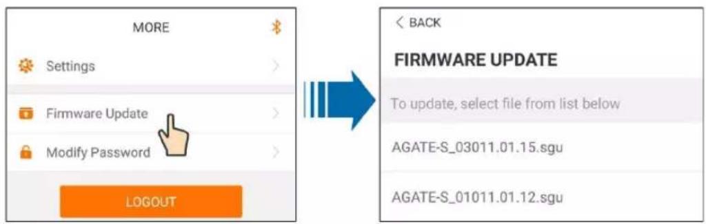
text_image
MORE Settings Firmware Update Modify Password LOGOUT BACK FIRMWARE UPDATE To update, select file from list below AGATE-S_03011.01.15.sgu AGATE-S_01011.01.12.sgufigure 7-22 Firmware Update
Select the desired update package to update the firmware.
! WARNING
Software update may cause inverter exception. Only professional personnel can update the software.
7.8.3 Changing Password
Tap "G" to enter the modify password screen, as shown in the following Figure.
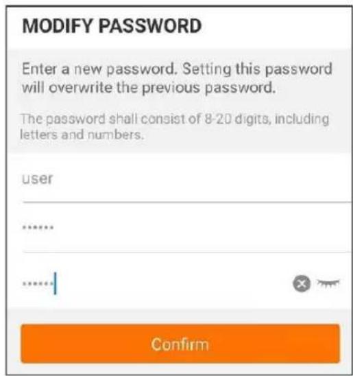
text_image
MODIFY PASSWORD Enter a new password. Setting this password will overwrite the previous password. The password shall consist of 8-20 digits, including letters and numbers. user ...... ...... Confirmfigure 7-23 Change password
The password shall consist of 8–20 digits, including letters and numbers.
8 System Decommissioning
8.1 Disconnecting the Inverter
For maintenance or other service work, the inverter must be switched off.
Proceed as follows to disconnect the inverter from the AC and DC power sources. Lethal voltages or damage to the inverter will follow if otherwise.
Step 1 Disconnect the external AC circuit breaker and secure it against reconnection.
Step 2 Rotate the DC and AC switches to the "OFF" position for disconnecting all of the PV string inputs.
Step 3 Wait about 5 minutes until the capacitors inside the inverter completely discharge.
Step 4 Ensure that the DC cable is current-free via a current clamp.
Step 5 Insert a MC4 wrench into the notch and press the wrench with an appropriate force to remove the DC connector.
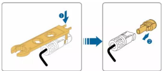
text_image
Diagram showing a mechanical component being processed, with labeled parts and directional arrows indicating process flow.Step 6 Ensure that the AC wiring terminals are voltage-free via a multimeter, and remove the AC wires and communication wires.
Step 7 Install the MC4 waterproof plugs.

For further disconnection and reconnection instructions, please visit the webpage of respective component manufacturer.
-- End
8.2 Dismantling the Inverter
CAUTION
Risk of burn injuries and electric shock!
- Do not touch any inner live parts until at least 5 minutes after disconnecting the inverter from the utility grid and the PV input.
Step 1 Refer to "5 Electrical Connection" for the inverter disconnection of all cables in reverse steps.
Step 2 Dismantle the inverter referring to "4 Mechanical Mounting" in reverse steps.
Step 3 If necessary, remove the wall-mounting bracket from the wall.
Step 4 If the inverter will be reinstalled in the future, please refer to "3.4 Inverter Storage" for a proper storage method.
-- End
8.3 Disposal of the Inverter
Users take the responsibility for the disposal of the inverter.
NOTICE
Some parts and devices of the inverter, such as the capacitors, may cause environmental pollution.
Do not dispose of the product together with household waste but in accordance with the disposal regulations for electronic waste applicable at the installation site.
9 Troubleshooting and Maintenance
9.1 Troubleshooting
Once a fault occurs in the inverter, the fault information can be displayed on the App interface, if there is any fault codes which cannot be found in the following list, please contact SUNGROW Service.
Fault codes and check methods are as follows:
| Fault code | Description | Check method |
| 002 | Grid overvoltage,The grid voltage is higher than the set protection value | Generally, the inverter will be reconnected to the grid after the grid returns to normal. If the fault occurs repeatedly:1. Measure the actual grid voltage, and contact the local electric power company for solutions if the grid voltage is higher than the set value.2. Check whether the protection parameters are appropriately set via the App or the LCD.3. Check whether the cross-sectional area of the AC cable meets the requirement.4. If the fault is not caused by the foregoing reasons and still exists, contact SUNGROW. |
| 003 | Grid transient overvoltage,The transient grid voltage is higher than the standard value. | Generally, the inverter will be reconnected to the grid after the grid returns to normal. If the fault occurs repeatedly, contact SUNGROW. |
| 004 | Grid undervoltage,The grid voltage is lower than the set protection value | Generally, the inverter will be reconnected to the grid after the grid returns to normal. If the fault occurs repeatedly:1. Measure the actual grid voltage, and contact the local electric power company for solutions if the grid voltage is lower than the set value.2. Check whether the protection parameters are appropriately set via the App or the LCD.3. Check whether the AC cable is firmly in place.4. If the fault is not caused by the foregoing reasons and still exists, contact SUNGROW. |
| 005 | Grid low voltage,The grid voltage is lower than the set protection value | Generally, the inverter will be reconnected to the grid after the grid returns to normal. If the fault occurs repeatedly:1. Measure the actual grid voltage, and contact the local electric power company for solutions if the grid voltage is lower than the set value.2. Check whether the protection parameters are appropriately set via the App or the LCD.3. Check whether the AC cable is firmly in place.4. If the faultis not caused by the foregoing reasons and still exists, contact SUNGROW. |
| 007 | AC instantaneous overcurrent, AC output current exceeds the upper limit of the inverter. | Generally, the inverter will be reconnected to the grid after the grid returns to normal. If the fault occurs repeatedly, contact SUNGROW. |
| 008 | Grid overfrequency,Grid frequency exceeds the upper limit of the inverter. | Generally, the inverter will be reconnected to the grid after the grid returns to normal. If the fault occurs repeatedly:1. Measure the actual grid frequency, and contact the local electric power company for solutions if the grid frequency is beyond the set range.2. Check whether the protection parameters are appropriately set via the App or the LCD.3. If the fault is not caused by the foregoing reasons and still exists, contact SUNGROW. |
| 009 | Grid underfrequency,Grid frequency is lower than the lower limit of the inverter. | |
| 010 | Grid power outage, AC switch or circuit is disconnected. | Generally, the inverter will be reconnected to the grid after the grid returns to normal. If the fault occurs repeatedly:1. Check whether the grid supplies power reliably.2. Check whether the AC cable is firmly in place.3. Check whether the AC cable is connected to the correct terminal (whether the live wire and the N wire are correctly in place).4. Check whether the AC circuit breaker is connected.5. If the fault is not caused by the foregoing reasons and still exists, contact SUNGROW. |
| 011 | Device anomaly | Wait for the inverter to return to normal.Disconnect the AC and DC switches, and reconnect the AC and DC switches 15 minutes later to restart the inverter.If the fault still exists, contact SUNGROW. |
| 012 | Excessive leakage current | 1. The fault can be caused by poor sunlight or damp environment, and the inverter will be reconnected to the grid after the environment is improved.2. If the environment is normal, check whether the AC and DC cables are well insulated.3. If the fault is not caused by the foregoing reasons and still exists, contact SUNGROW. |
| 013 | Grid abnormal, the grid voltage or frequency is out of the permissible range, and the inverter cannot be connected to the grid normally. | Generally, the inverter will be reconnected to the grid after the grid returns to normal. If the fault occurs repeatedly:1. Measure the actual grid frequency, and contact the local electric power company for solutions if the grid parameter exceeds the set value.2. If the fault is not caused by the foregoing reasons and still exists, contact SUNGROW. |
| 014 | 10-minute grid overvoltage, the grid voltage exceeds the preset AC voltage of the inverter for a long time. | Wait for the inverter to return to normal.If the fault occurs repeatedly, contact SUNGROW. |
| 015 | Grid overvoltage, The grid voltage is higher than the set protection value | Generally, the inverter will be reconnected to the grid after the grid returns to normal. If the fault occurs repeatedly:1. Measure the actual grid voltage, and contact the local electric power company for solutions if the grid voltage is higher than the set value.2. Check whether the protection parameters are appropriately set via the App or the LCD.3. Check whether the cross-sectional area of the AC cable meets the requirement.4. If the fault is not caused by the foregoing reasons and still exists, contact SUNGROW. |
| 016 | Output overload, The configured module power is excessively large and out of the normal operation range of the inverter. | Wait for the inverter to return to normal.If the fault still exists, contact SUNGROW. |
| 017 | Grid voltage unbalance, the inverter detects unbalanced three-phase grid voltage | Generally, the inverter will be reconnected to the grid after the grid returns to normal. If the fault occurs repeatedly:1. Measure the actual grid voltage. If grid phase voltages differ greatly, contact the power company for solutions.2. If the voltage difference between the three phases is within the permissible range of the local power company, modify the grid voltage imbalance parameter through the App or LCD screen.3. If the fault is not caused by the foregoing reasons and still exists, contact SUNGROW. |
| 019-020 | Device anomaly | Wait for the inverter to return to normal.Disconnect the AC and DC switches, and reconnect the AC and DC switches 15 minutes later to restart the inverter.If the fault still exists, contact SUNGROW. |
| 021-022 | Device anomaly | Wait for the inverter to return to normal.Disconnect the AC and DC switches, and reconnect the AC and DC switches 15 minutes later to restart the inverter.If the fault still exists, contact SUNGROW. |
| 024-025030-034 | Device anomaly | Wait for the inverter to return to normal.Disconnect the AC and DC switches, and reconnect the AC and DC switches 15 minutes later to restart the inverter.If the fault still exists, contact SUNGROW. |
| 036 | Temperature anomaly, The temperature of the power module is excessively high and out of the safe range. | 1. Check whether the inverter is directly exposed to sunlight. If so, take some shading measures.2. Check and clean the air ducts.3. Check whether there is 070 (fan anomaly) alarm via the App or the LCD. If so, replace the fans. |
| 037 | Temperature anomaly, The temperature of the interior of the inverter is excessively high and out of the safe range. | 1. Check whether the inverter is directly exposed to sunlight. If so, take some shading measures.2. Check and clean the air ducts.3. Check whether there is 070 (fan anomaly) alarm via the App or the LCD. If so, replace the fans. |
| 038 | Device anomaly | Wait for the inverter to return to normal.Disconnect the AC and DC switches, and reconnect the AC and DC switches 15 minutes later to restart the inverter.If the fault still exists, contact SUNGROW. |
| 039 | Low system insulation resistance, which is generally caused by poor insulation to ground of the module/cable or by rainy and damp environment. | Wait for the inverter to return to normal. If the fault occurs repeatedly:1. Check whether the ISO resistance protection value is excessively high via the App or the LCD, and ensure that it complies with the local regulations.2. Check the resistance to ground of the string and DC cable. Take correction measures in case of short circuit or damaged insulation layer.3. If the cable is normal and the fault occurs on rainy days, check it again when the weather turns fine.4. If the fault is not caused by the foregoing reasons and still exists, contact SUNGROW. |
| 040-042 | Device anomaly | Wait for the inverter to return to normal.Disconnect the AC and DC switches, and reconnect the AC and DC switches 15 minutes later to restart the inverter.If the fault still exists, contact SUNGROW. |
| 043 | Low ambient temperature, the ambient temperature is lower than the temperature at which the inverter can operate normally. | Shutdown and disconnect the inverter. Restart the inverter when the ambient temperature falls within the operation temperature range. |
| 044-046 | Device anomaly | Wait for the inverter to return to normal.Disconnect the AC and DC switches, and reconnect the AC and DC switches 15 minutes later to restart the inverter.If the fault still exists, contact SUNGROW. |
| 047 | PV input configuration abnormal, PV input mode error | Shutdown and disconnect the inverter. Reset the input mode of the PV array. |
| 048-050 | Device anomaly | Wait for the inverter to return to normal.Disconnect the AC and DC switches, and reconnect the AC and DC switches 15 minutes later to restart the inverter.If the fault still exists, contact SUNGROW. |
| 053-056 | ||
| 059-060 | ||
| 070 Fan alarm | 1. Check whether the fans operate normally and are blocked by sundries. If they are blocked, clear the sundries.2. If a fan does not operate normally, Shutdown and disconnect the inverter to replace the fan. | |
| 071 AC-side SPD alarm | Check the SPD, and replace it if necessary. | |
| 072 DC-side SPD alarm | ||
| 076 | Device anomaly | Wait for the inverter to return to normal.Disconnect the AC and DC switches, and reconnect the AC and DC switches 15 minutes later to restart the inverter.If the fault still exists, contact SUNGROW. |
| 078-081 PVx abnormal | 1. Check if the xth PV string needs to be connected.If not, ignore the alarm; andIf so, check the connection status and make sure it is connected reliably.2. Check if the xth DC fuse is damaged. If so, replace the fuse.3.If the fault is not caused by the foregoing reasons and still exists, contact SUNGROW.*The code 078 to code 081 are corresponding to PV 1 to PV 4 respectively. | |
| 087 | Electric arc detection module abnormal | The inverter can operate normally.1. Check whether the related cable connection and terminals are abnormal, and check whether the ambient environment is abnormal. If so, remove the corresponding abnormality.2. If the fault is not caused by the foregoing reasons and still exists, contact SUNGROW. |
| 088 Electric arc fault | 1. Disconnect the DC inputs and check whether DC cables are damaged, whether the wiring terminals or fuses are loose or in poor contact, and whether component parts are burnt. If so, take corresponding corrective measures.2. After taking corresponding measures in step 1, reconnect the DC inputs. Remove the arc fault through the App or LCD screen so that the inverter will recover to be normal.3. If the fault is not caused by the foregoing reasons and still exists, contact SUNGROW. | |
| 105 | Protection self-check failure on grid side | Restart the inverter or clear the fault through the App.If the fault still exists, contact SUNGROW. |
| 106 | Grounding cable fault | 1. Check whether the AC cable is correctly connected.2. Check whether the insulation between the ground cable and the live wire is normal.3. If the fault is not caused by the foregoing reasons and still exists, contact SUNGROW. |
| 116-117 | Device anomaly | Wait for the inverter to return to normal.Disconnect the AC and DC switches, and reconnect the AC and DC switches 15 minutes later to restart the inverter.If the fault still exists, contact SUNGROW. |
| 220~227 PVx abnormal | 1. Check if the xth PV string needs to be connected.If not, ignore the alarm; andIf so, check the connection status and make sure it is connected reliably.2. Check if the xth DC fuse is damaged. If so, replace the fuse.3.If the fault is not caused by the foregoing reasons and still exists, contact SUNGROW.*The code 220 to code 227 are corresponding to PV 5 to PV 12 respectively. | |
| 448~471 | String x reverse connection fault | 1. Check whether the corresponding string is of reverse polarity. If so, disconnect the DC switch and adjust the polarity when the solar radiation is low and the string current drops below 0.5A.2. If the fault is not caused by the foregoing reasons and still exists, contact SUNGROW.*The code 448 to code 471 are corresponding to string 1 to string 24 respectively. |
| 532-547 | String x reverse connection alarm | 1. Check whether the corresponding string is of reverse polarity. If so, disconnect the DC switch and adjust the polarity when the solar radiation is low and the string current drops below 0.5A.2. If the fault is not caused by the foregoing reasons and still exists, contact SUNGROW.*The code 532 to code 547 are corresponding to string 1 to string 16 respectively. |
| 548-563 | String x output current anomaly | 1. Check whether the corresponding module is sheltered. If so, remove the shelter and ensure module cleanness.2. Check the module for abnormal aging.3. If the fault is not caused by the foregoing reasons and still exists, contact SUNGROW.*The code 548 to code 563 are corresponding to string 1 to string 16 respectively. |
| 564-571 | String x reverse connection alarm | 1. Check whether the corresponding string is of reverse polarity. If so, disconnect the DC switch and adjust the polarity when the solar radiation is low and the string current drops below 0.5A.2. If the fault is not caused by the foregoing reasons and still exists, contact SUNGROW.*The code 564 to code 571 are corresponding to string 17 to string 24 respectively. |
| 580-587 | String x output current anomaly | 1. Check whether the corresponding module is sheltered. If so, remove the shelter and ensure module cleanness.2. Check the module for abnormal aging.3. If the fault is not caused by the foregoing reasons and still exists, contact SUNGROW.*The code 580 and 587 are corresponding to string 17 and string 24 respectively. |
9.2 Maintenance
! DANGER
Risk of inverter damage or personal injury due to incorrect service!
- Always keep in mind that the inverter is powered by dual sources: PV strings and utility grid.
Before performing any service work, observe the following procedure. - Disconnect the AC circuit breaker and then set the DC load-break switch of the inverter to OFF;
- Wait at least 5 minutes for inner capacitors to discharge completely;
- Verify that there is no voltage or current before pulling any connector.
CAUTION
If the PV system is equipped with RSDs, please pay attention to the following issue when doing the maintenance job to a certain inverter:
Even if the target inverter is shut down, the RSDs in the corresponding PV strings connected to this inverter maybe still keep alive due to PLC signals injected from other alive inverters once the DC cables are not separated from inverter to inverter. In this scenario, it is recommended to remove the PV strings from the target inverter in first priority as normal, then going on with the maintenance job.
CAUTION
Keep non-related persons away!
A temporary warning sign or barrier must be posted to keep non-related persons away while performing electrical connection and service work.
NOTICE
Restart the inverter only after removing the fault that impairs safety performance.
As the inverter contains no component parts that can be maintained, never arbitrarily replace any internal components.
For any maintenance requirement, please contact SUNGROW. Otherwise, SUNGROW shall not be held liable for any damage caused.
9.2.1 Routine Maintenance
Item Method Period
| System clean | Check the temperature and dust of the inverter. Clean the inverter enclosure if necessary.Check if the air inlet and outlet are normal. Clean the air inlet and outlet, if necessary. | Six months to a year (-depending on the dust content in the air.) |
| Fans | Check whether there is fan warning using App.Check whether there is any abnormal noise when the fan is turning.Clean or replace the fans if necessary (see the following section). | Once a year |
| Cable entry | Check whether the cable entry is insufficiently sealed or the gap is excessively large, and reseal the entry when necessary. | Once a year |
| Electrical Connection | Check whether all cable are firmly in place.Check whether a cable is damaged, especially the part contacting the metal enclosure. | Six months to a year |
9.2.2 Maintenance Instruction
Cleaning Air Inlet and Outlet
A significant amount of heat is generated in the process of running the inverter. The inverter adopts a controlled forced-air cooling method.
In order to maintain good ventilation, please check to make sure the air inlet and outlet are not blocked.
Clean the air inlet and outlet with soft brush or vacuum cleaner if necessary.
Fan Maintenance
! DANGER
- Stop the inverter and disconnect it from all power supplies before maintenance.
- Lethal voltage still exists in the inverter. Please wait for at least 5 minutes and then perform maintenance work.
- Only qualified electricians can maintain the fans.
Fans inside the inverter are used to cool the inverter during operation. If the fans do not operate normally, the inverter may not be cooled down and inverter efficiency may decrease. Therefore, it is necessary to clean dirty fans and replace the broken fans in a timeiy manner. The operation procedure is as follows:
Step 1 Stop the inverter (see 8.1 Disconnecting the Inverter).
Step 2 Loosen the screw on the sealing plate of the fan module.
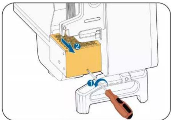
text_image
Diagram showing a sewing machine's internal component with labeled parts and a tool inserted, likely illustrating a sewing or repair operation.Step 3 Press the tab of the latch hook, unplug the cable connection joint outwards, and loosen the screw on the fan holder.
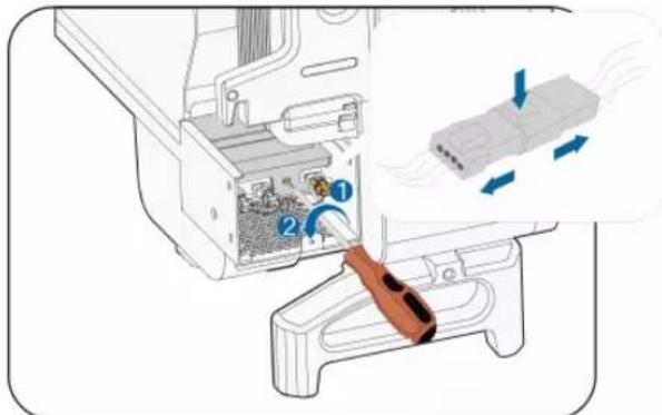
text_image
Diagram showing a device's internal structure with numbered components and airflow indicators, likely illustrating a mechanical or fluid dynamics concept.Step 4 Pull out the fan module, clean the fans with soft brush or vacuum cleaner, and replace them when necessary.
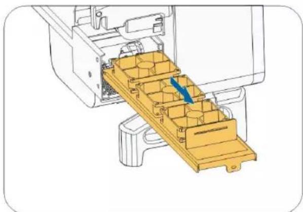
natural_image
Technical illustration of a mechanical assembly with a yellow plastic tray and blue arrow indicating direction (no text or symbols)Step 5 Reinstall the fan back to the inverter in reverse order and restart the inverter.
-- End
10 Appendix
10.1 Technical Data
| Parameters SG36CX-US SG60CX-US | ||
| Input (DC) | ||
| Max. PV input voltage 1000V | ||
| Min.PV input voltage/Startup input voltage | 200V / 250V | |
| Nominal PV input voltage 710V | ||
| MPP voltage range 200–1000V | ||
| MPP voltage range for rated power | 550V–850V(1) | |
| No. of independent MPP inputs | 4 | 6 |
| Max. number of PV strings per MPPT | 2 | |
| Max. PV input current 26A*4 26A*6 | ||
| Max.DC Short-circuit current per MPPT | 45A | |
| Output (AC) | ||
| AC output power | 36 kVA @ 113 °F (45°C) / 30 kVA @ 122 °F (50 °C) | 60 kVA @ 113 °F (45 °C) / 50 kVA @ 122 °F (50 °C) |
| Max. AC output current | 43.3A 72.2A | |
| Nominal AC voltage | 3 / N / PE, 277 / 480 V | |
| AC voltage range 422–528V | ||
| Nominal grid frequency/Grid frequency range | 60 Hz / 55–65 Hz | |
| Total harmonic distortion (THD) | < 3 % (at nominal power) | |
| DC current injection | <0.5%In | |
| Power factor at nominal power / Adjustable power factor | >0.99 / 0.8 leading –0.8 lagging | |
| Feed-in phases / Connection phases | 3/3 | |
| Efficiency | ||
| Max. efficiency | 98.60% | 98.80% |
| CEC efficiency | 98.00% | 98.00% |
| Protection | ||
| Parameters SG36CX-US SG60CX-US | |
| DC reverse connection protection | Yes |
| AC short-circuit protection | Yes |
| Leakage current protection Yes | |
| Grid monitoring | Yes |
| DC switch | Yes |
| AC switch | Yes |
| PV string monitoring Yes | |
| Arc fault circuit interrupter (AFCI) Yes | |
| PID Recovery function Yes | |
| Overvoltage protection | DC Type II / AC Type II |
| Rapid Shutdown | Yes |
| General Data | |
| Dimensions (W*H*D) | Inverter: 702 * 595 *310 mm (27.6" * 23.4"* 12.2") Wire-Box: 231 * 295 *234 mm (9.1" * 11.6"* 9.2") |
| Weight | 54 kg (119.0 lbs) 65 kg (143.3 lbs) |
| Isolation method | Transformerless |
| Degree of protection | Type 4X (NEMA 4X, IP66) |
| Night power consumption < 2W * | |
| Operating ambient temperature range | -30 to 60 °C (> 45 °C derating) -22 to 140 °F (>113°F derating) |
| Allowable relative humidity range (non-condensing) | 0 - 100% |
| Cooling method | Smart forced air cooling |
| Max. operating altitude | 4000 m / 13123.4 ft(> 3000 m 9842.5 ft derating) |
| Display | LED, Bluetooth + App |
| Communication | RS485 / optional: WiFi and Ethernet |
| Third-Party communication protocol | SunSpec Modbus |
| DC connection type | MC4 (#12 - #10AWG) |
| ACconnection type | OT (#6 - 2/0AWG, CuOT (#5 - 2/0AWG, Cu or or Al ) AI ) |
| Compliance | UL1741, UL 1741 SA, CA Rule 21, IEEE 1547, IEEE 1547.1, CSA C22.2, No.107.1-01, UL 1699B and FCC Part 15, UL1998, Rule 14, NEC 2023, Sunspec Rapid Shutdown |
| Grid Support | LVRT, HVRT, active & reactive power control and power ramp rate control |
* Night power consumption excludes the optional power from PID recovery.
Note(1):
- The voltage difference between MPPTs should be less than 80 V.
- The voltage of the configured string should be higher than the lower limit of the rated MPPT voltage.
10.2 Wring Distance of DI Dry Contact
The maximum wiring distance of DC dry contact must meet the requirements in the Table below. The wiring distance L is the total length of all DI signal cables.
$$ L = 2 \sum_ {k = 1} ^ {n} L _ {k} $$
L_K refers to the cable length in one direction between the DI dry contact terminal of the k inverter and the corresponding terminal of the (k-1)verter.
table 10-1 Correspondence between number of inverters and maximum wiring distance
| Number of inverter | Maximum wiring distance(unit:m) | |
| 16AWG / 1.31m2n | 17AWG / 1.026m2n | |
| 1 13030 10552 | ||
| 2 6515 5276 | ||
| 3 4343 3517 | ||
| 4 3258 2638 | ||
| 5 2606 2110 | ||
| 6 2172 1759 | ||
| 7 1861 1507 | ||
| 8 1629 1319 | ||
| 9 1448 1172 | ||
| 10 1303 1055 | ||
| 11 | 1185 | 959 |
| 12 1086 879 | ||
| 13 1002 812 | ||
| 14 931 754 | ||
| 15 869 703 | ||
| 16 814 660 | ||
| 17 766 621 | ||
| 18 724 586 | ||
| 19 686 555 | ||
| 20 652 528 | ||
| 21 620 502 | ||
| 22 592 480 | ||
| 23 567 459 | ||
| 24 543 440 | ||
| 25 521 422 | ||
NOTICE
In case the specification of the cable used is not included in the Table above, when there is only one inverter, ensure that the line impedance of the input node is less than 300Ω; and when there are multiple inverters connected in the daisy chain, ensure that the impedance is less than 300Ω/number of inverter.
10.3 Quality Assurance
When product faults occur during the warranty period, SUNGROW will provide free service or replace the product with a new one.
Evidence
During the warranty period, the customer shall provide the product purchase invoice and date. In addition, the trademark on the product shall be undamaged and legible. Otherwise, SUNGROW has the right to refuse to honor the quality guarantee.
Conditions
• After replacement, unqualified products shall be processed by SUNGROW.
- The customer shall give SUNGROW a reasonable period to repair the faulty device.
Exclusion of Liability
In the following circumstances, SUNGROW has the right to refuse to honor the quality guarantee:
- The free warranty period for the whole machine/components has expired.
- The device is damaged during transport.
- The device is incorrectly installed, refitted, or used.
- The device operates in harsh environment, as described in this manual.
- The fault or damage is caused by installation, repairs, modification, or disassembly performed by a service provider or personnel not from SUNGROW.
- The fault or damage is caused by the use of non-standard or non-SUNGROW components or software.
- The installation and use range are beyond stipulations of relevant international standards.
- The damage is caused by unexpected natural factors, i.e. force majeure.
For faulty products in any of above cases, if the customer requests maintenance, paid maintenance service may be provided based on the judgment of SUNGROW.
10.4 Contact Information
In case of questions about this product, please contact us.
We need the following information to provide you the best assistance:
- Model of the device
- Serial number of the device
- Fault code/name
- Brief description of the problem
For detailed contact information, please visit: https://en.sungrowpower.com/contactUS.