
BSC200 - Battery Sungrow - Free user manual and instructions
Find the device manual for free BSC200 Sungrow in PDF.


| Product Type | Lithium-ion Battery System |
| Model | BSC200 |
| Brand | Sungrow |
| Nominal Energy Capacity | 200 kWh |
| Usable Energy Capacity | 180 kWh (90% DoD) |
| Nominal Voltage | 800 V |
| Voltage Range | 600 V – 1000 V |
| Max Continuous Charge/Discharge Power | 100 kW |
| Peak Power (10s) | 150 kW |
| Round-trip Efficiency | ≥ 95% |
| Cooling Method | Liquid Cooling (optional) |
| Dimensions (W × D × H) | 1200 mm × 800 mm × 2200 mm |
| Weight | ≈ 2000 kg |
| Operating Temperature Range | -20°C to 50°C |
| Relative Humidity | 0% – 95% (non-condensing) |
| Max Altitude | 3000 m |
| Protection Class | IP20 |
| Installation Type | Indoor / Outdoor (with enclosure) |
| Communication Interfaces | CAN, RS485, Ethernet |
| Certifications | IEC 62619, UN 38.3, CE |
| Maintenance | Minimal; periodic visual inspection and software updates |
| Warranty | 10 years or 6000 cycles (whichever first) |
Frequently Asked Questions - BSC200 Sungrow
User questions about BSC200 Sungrow
0 question about this device. Answer the ones you know or ask your own.
Ask a new question about this device
Download the instructions for your Battery in PDF format for free! Find your manual BSC200 - Sungrow and take your electronic device back in hand. On this page are published all the documents necessary for the use of your device. BSC200 by Sungrow.
USER MANUAL BSC200 Sungrow
natural_image
Line art illustration of the Earth with wind turbines and a globe, symbolizing environmental sustainability (no text or symbols)All Rights Reserved
All Rights Reserved
No part of this document can be reproduced in any form or by any means without the prior written permission of SUNGROW ENERGY STORAGE TECHNOLOGY CO., LTD (herein-after "SUNGROW").
Trademarks
SUNGROW and other Sungrow trademarks used in this manual are owned by
SUNGROW.
All other trademarks or registered trademarks mentioned in this manual are owned by their respective owners.
Software Licenses
- It is prohibited to use data contained in firmware or software developed by SUNGROW, in part or in full, for commercial purposes by any means.
- It is prohibited to perform reverse engineering, cracking, or any other operations that compromise the original program design of the software developed by SUNGROW.
About This Manual
The manual mainly describes the product information, guidelines for installation, operation and maintenance. The manual cannot include complete information about the energy storage system. You can get additional information about other devices at www.sungrow-power.com or on the webpage of the respective component manufacturer.
Validity
This manual is valid for the following converter type:
• SD175HV DC/DC converter
They will be referred to as “converter” hereinafter unless otherwise specified.
Target Group
This manual is intended for converter owners who will have the ability to interact with the converter and qualified personnel who are responsible for the installation and commissioning of the converter. Qualified personnel should have the following skills:
- Training for installation and commissioning of electrical system, as well as dealing with hazards
- Knowledge of the manual and other related documents
- Knowledge of the local regulations and directives
How to Use This Manual
Read the manual and other related documents before performing any work on the converter. Documents must be stored carefully and be available at all times.
Contents may be periodically updated or revised due to the product development. The manual content of subsequent versions of the converter may be subject to change. The latest manual can be found at support.sungrowpower.com.
Symbols
To ensure the safety of the users and their properties when they use the product and to make sure that the product is used in an optimal and efficient manner, this manual provides users with the relevant safety information which is marked by the following symbols.
Below is a list of symbols that are used in this manual. Review them carefully to make better use of this manual.
! DANGER
Indicates a hazard with a high level of risk that, if not avoided, will result in death or serious injury.
WARNING
Indicates a hazard with a medium level of risk that, if not avoided, could result in death or serious injury.
CAUTION
Indicates a hazard with a low level of risk that, if not avoided, could result in minor or moderate injury.
NOTICE
Indicates a situation that, if not avoided, could result in equipment or property damage.

Indicates additional information, emphasized contents or tips that may be helpful, e.g. to help you solve problems or save time.
Contents
All Rights Reserved ....I
About This Manual....II
1 Safety ....1
1.1 Storage Battery .... 1
1.2 Converter....2
1.3 Skills of Qualified Personnel .... 3
2 Product Description ....4
2.1 Function Description ......4
2.1.1 Intended Usage 1....4
2.1.2 Intended Usage 2....5
2.2 Product Introduction....5
2.2.1 Type Description ....5
2.2.2 Appearance....6
2.2.3 Dimensions and Weight....7
2.2.4 LED Indicator Panel 7
2.2.5 DC Switch 8
2.2.6 Emergency Stop Button....9
2.3 Circuit Diagram ......9
2.4 Function Description ......10
3 Unpacking and Storage 11
3.1 Unpacking and Inspection 11
3.2 Identifying the Converter 11
3.3 Converter Storage ....13
4 Mechanical Mounting ....14
4.1 Safety during Mounting 14
4.2 Location Selection ....14
4.2.1 Installation Environment Requirements....14
4.2.2 Carrier Requirements ....15
4.2.3 Installation Angle Requirements ....15
4.2.4 Installation Clearance Requirements ....15
4.3 Installation Tools....15
4.4 Moving the Converter....16
4.5 Preparation before Mounting .... 17
5 Electrical Connection .... 19
5.1 Safety Instructions ....19
5.2 Terminal Description ...... 19
5.3 Electrical Connection Overview ......20
5.4 Additional Grounding Connection....22
5.4.1 Additional Grounding Requirements ...... 22
5.4.2 Connection Procedure....22
5.5 DC Cable Connection 23
5.6 PV Connector Connection 25
5.7 Ethernet Connection ....27
5.8 Communication Connection ....28
6 Commissioning ....33
6.1 Inspection before Commissioning ....33
6.2 Commissioning Procedure ....33
7 iSolarCloud APP ....34
7.1 Brief Introduction ......34
7.2 Download and Install....34
7.3 Login 35
7.3.1 Requirements ...... 35
7.3.2 Login Steps ...... 35
7.4 Home page 36
7.5 Running Information ....38
7.6 History Record .... 39
7.6.1 Fault Alarm Records....40
7.6.2 Power Yields Records 41
7.6.3 Event Records 42
7.7 More....43
7.7.1 Boot 43
7.7.2 Hot Standby....43
7.7.3 Shutdown 44
7.7.4 System Parameters....44
7.7.5 Settings....45
8 System Decommissioning ....54
8.1 Disconnecting the Converter ....54
8.2 Dismantling the Converter ....54
8.3 Disposal of the Converter....54
9 Troubleshooting and Maintenance ....56
9.1 Troubleshooting ....56
9.2 Maintenance ....57
10 Appendix 59
10.1 Technical Data....59
10.2 Quality Assurance ....60
10.3 Contact Information ......60
1 Safety
The device has been designed for the power industry. You need to follow the applicable safety rules during its installation, trial operation, operations and maintenance. Incorrect operation or work may cause:
- Injury or death to the operator or a third party;
- Damage to the device and other properties.
Follow all the safety guidelines stated in this manual strictly to protect yourself from any danger and harm.
The precautions to take during the operations are described in details in the corresponding chapters.

- The safety instructions in this manual cannot cover all the precautions that should be followed. Perform operations considering actual onsite conditions.
- SUNGROW shall not be held liable for any damage caused by violation of the safety instructions in this manual.
1.1 Storage Battery
For battery storage power stations, the voltage between the positive and negative electrodes of the storage battery pack is very high. If the operators touch it accidentally, they may get an electric shock which can be fatal.
! DANGER
High voltage between the positive and negative electrodes of the storage battery pack that can be fatal!
- When the equipment is under maintenance, make sure that the battery storage converter is not connected to the storage battery pack.
- Set a warning sign at the point of disconnection to make sure that they will not be accidentally reconnected.
1.2 Converter
! DANGER
Electric shock risk!
- Make sure that the external casing of the chassis is intact and closed to keep the operators and their properties safe from harm or injury. Please do not open the external casing of the converter when the converter is working or connected, otherwise Sungrow Power Supply Co., Ltd. shall not be held liable for related consequences.
WARNING
Risk of damage to converter or personal injury!
- Do not plug in or unplug the DC connector when the converter is working.
- Even when the converter is disconnected, the voltage inside is still high. Wait at least five minutes before you handle the converter.
WARNING
All safety instructions, warning labels, and nameplate on the converter:
- Must be clearly legible.
- Should not be removed or covered.
CAUTION
Risk of burns due to hot components!
Do not touch any hot parts (such as heat sink) during operation. Only the DC switch can safely be touched at any time.
NOTICE
The parameters of the converter must be configured by qualified technical personnel according to the standards of the local power grid.
NOTICE
Do not touch the printed circuit board or other electrostatic sensitive components as you may damage the device.
- Do not touch the circuit board unnecessarily.
- Observe the regulations to protect against electrostatic and wear an anti-static wrist strap.
Warning Label
| Symbol | Explanation |
 | Danger to life due to high voltages!Only qualified personnel can open and service the converter. |
 | Disconnect the converter from all the external power sources before service! |
 | Do not touch live parts until 5minutes after disconnection from the power sources. |
 | There is a danger from a hot surface that may exceed 60°C. |
 | Check the user manual before service! |
1.3 Skills of Qualified Personnel
All installations should be performed by technical personnel. They should have:
- Training in the installation and commissioning of the electrical system, as well as the dealing with hazards.
- Knowledge of the manual and other related documents.
- Knowledge of the local regulations and directives.
2 Product Description
2.1 Function Description
2.1.1 Intended Usage 1
The DC converter is used to convert the DC power from the battery into DC power that the inverter can accept for inversion. It can also convert the DC power output from the converter into DC power that can be used to charge the battery.
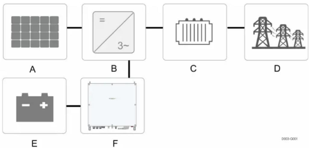
flowchart
graph LR
    A["太阳能板"] --> B["3~ Screen"]
    B --> C["Grid"]
    C --> D["Tower Tower"]
    E["Battery"] --> F["Grid with Battery"]
    F --> B
figure 2-1 Inended Usage1
Note 1: *The image shown here is for reference only. The actual product you receive may differ.
| Item Description | |
| A PV strings | |
| B | Power conversion equipment such as inverters and battery storage converters |
| C Transformer | |
| D Utility grid or Load | |
| E Battery | |
| F Converter | |
2.1.2 Intended Usage 2
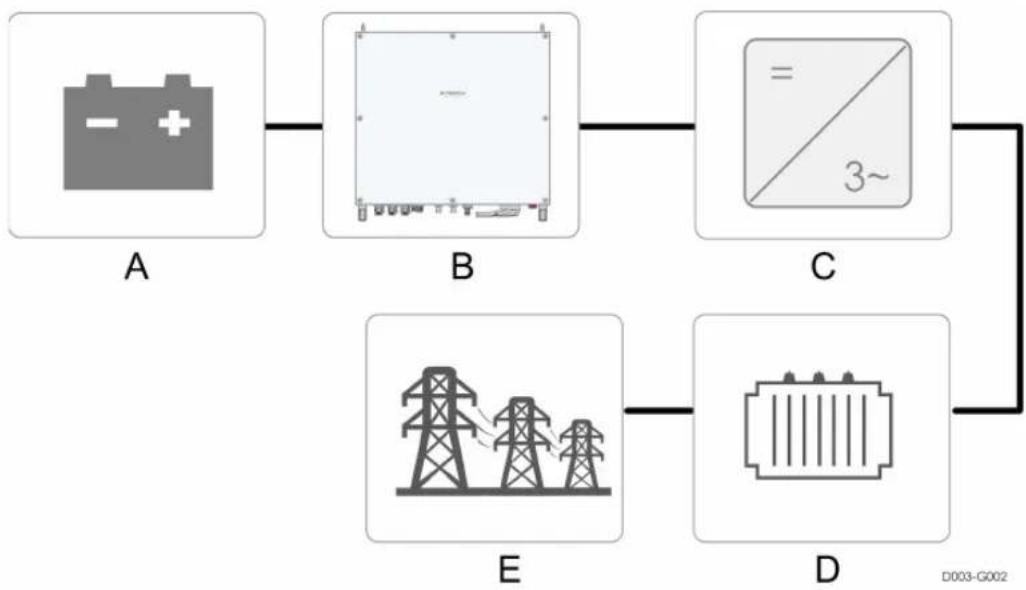
flowchart
graph LR
    A[" Battery "] --> B[" Battery "]
    B --> C[" Circuit "]
    C --> D[" Power Transmission "]
    B --> E[" Power Tower 1"]
    B --> E
    C --> E
    D --> E
figure 2-2 Intended Usage 2
Note 1: *The image shown here is for reference only. The actual product you receive may differ.
| Item Description |
| A Battery |
| B Converter |
| C Power conversion equipment such as inverters and battery storage converters |
| D Transformer |
| E Utility grid or Load |
2.2 Product Introduction
2.2.1 Type Description
The device type description is as follows:
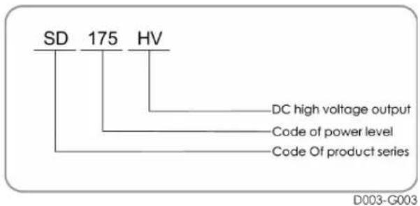
table 2-1 Power Level Description
| Type Nominal Output Power MAX.Output Power |
| SD175HV 175kW 175kW |
The device type can be found on the nameplate attached to the side of the converter. For details, refer to "Identifying the Converter"
2.2.2 Appearance
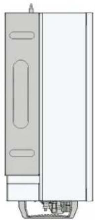
The appearance of the converter is shown as follow.
natural_image
Technical line drawing of a vertical panel or enclosure with internal components (no text or symbols)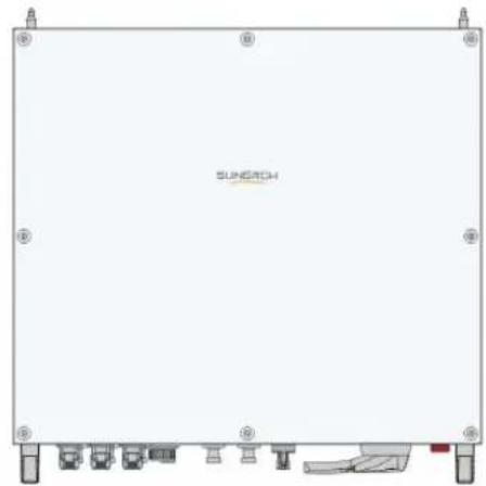
natural_image
Front view of a white industrial or electronic component with mounting feet and a small mechanical assembly at the bottom (no visible text or symbols)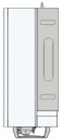
natural_image
Technical line drawing of a vertical cabinet or enclosure with internal components (no text or symbols)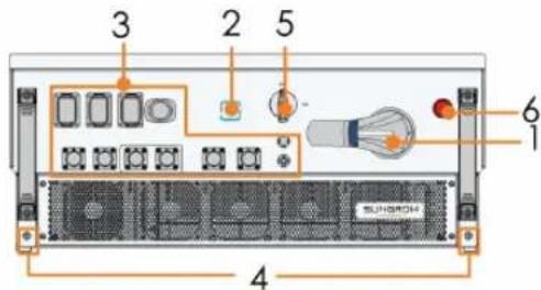
D003-G004
figure 2-3 Converter appearance
*The image shown here is for reference only. The actual product you receive may differ.
| No. | Name | Description |
| 1 | DC Switch | To safely cut off the electrical connection between the inverter and battery. |
| 2 | LED indicator | Indicates the present working state of the converter. |
| 3 | Wiring area | DC switches, and communication terminals. |
| 4 | Grounding terminal | To ground the electrical protection of the equipment. |
| 5 | Auxiliary power switch | To safely cut off the electrical connection between the converter and external device. |
| 6 | Emergency Stop Button | Only for emergencies. Press this button to immediately disconnect the converter from the upstream and downstream equipment. |
2.2.3 Dimensions and Weight
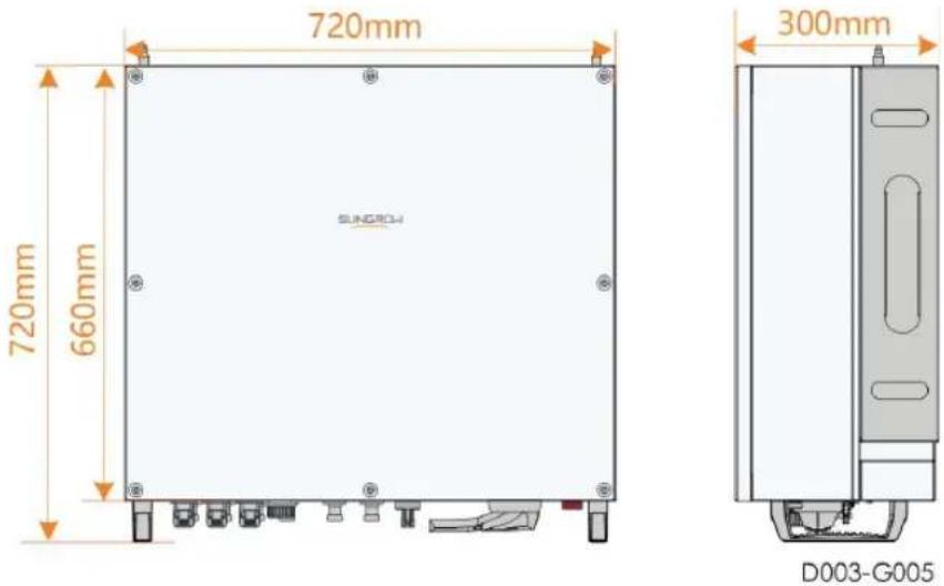
figure 2-4 Dimensions of the Converter (in mm)
| Weight (kg) |
| 75kg |
2.2.4 LED Indicator Panel
As an HMI, the LED indicator panel on the converter bottom panel indicates the present working state of the converter.
table 2-2 LED indicator description
| LED indicator | LED state Definition | |
 | ON | The device is connected to the grid and operating normally. |
| Fast blink | The Bluetooth communication is connected and there is data communication. | |
| Blue | (Period: 0.2s) | No system fault occurs. |
| Slow flash (Period: 2s) | The device is in standby or startup state (not feeding power into the grid). | |
 | ON | A fault occurred. ( The converter is power off immediately.) |
| Twinkling (Period: 0.2s) | The Bluetooth communication is connected and there is data communication. System fault occurs. | |
| Red | ||
 | OFF | The converter is powered off. |
| OFF | ||
2.2.5 DC Switch
! WARNING
Make sure the load switch is open before you power on the converter. Do not close the load switch when there is electricity in the converter. Do not open the load switch when the converter is running.
The converter is equipped with two DC switches, which are marked with "DC Switch 1" and "DC Switch 2" using silk-screen printing.
"DC Switch 1" is used to safely cut off the electrical connection between the converter and inverter.
“DC Switch 2” is the auxiliary power supply switch that can safely disconnect the auxiliary power supply side power of the DC converter.
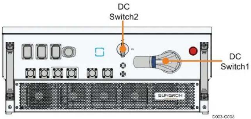
figure 2-5 Bottom view
2.2.6 Emergency Stop Button
Press the emergency stop button to quickly stop the machine in an emergency. The position is shown in the figure below.
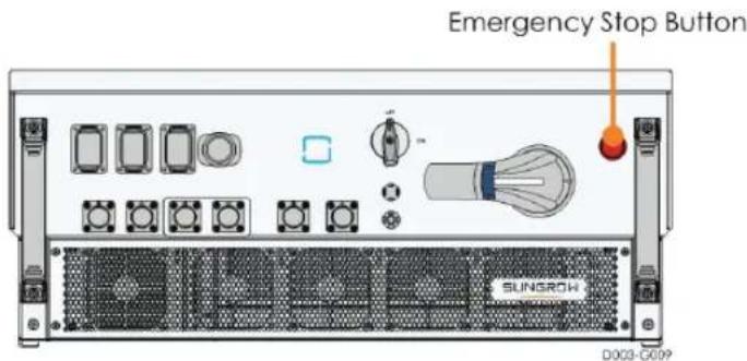
figure 2-6 Bottom view
! WARNING
Before maintenance, press the emergency stop button to prevent the machine from being connected to the power supply due to background misoperation.
2.3 Circuit Diagram
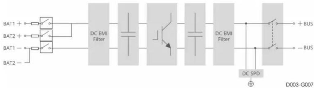
The converter can convert the DC current from the battery into DC current that can be accepted by power conversion equipment such as inverters and battery storage converters. This is used to perform the power conversion. It is also be used to convert the DC power output from the power conversion devices into DC power can be used to charge the battery. The specific conversion direction is determined by the state of the battery and can be controlled by the monitoring system.
Design principles of the converters are as follows:
flowchart
graph LR
    A["BAT1 +"] --> B["DC EMI Filter"]
    C["BAT2 +"] --> B
    D["BAT1 -"] --> B
    E["BAT2 -"] --> B
    B --> F["DC EMI Filter"]
    F --> G["DC SPD"]
    G --> H["+ BUS"]
    G --> I["- BUS"]
    H --> J["D003-G007"]
    I --> J
    style A fill:#f9f,stroke:#333
    style C fill:#f9f,stroke:#333
    style D fill:#f9f,stroke:#333
    style E fill:#f9f,stroke:#333
    style F fill:#ccf,stroke:#333
    style G fill:#ccf,stroke:#333
    style H fill:#ccf,stroke:#333
    style I fill:#ccf,stroke:#333
figure 2-7 Circuit diagram
2.4 Function Description
The converter is equipped with the following functions:
Conversion
Convert the DC power in the converter or battery into DC power that can be accepted by the equipment on the other side.
Data storage and display
The converter stores system information including operation information and fault records. The system information can be uploaded to smartphones and host machine via communication methods like Bluetooth and RS485. Users can view the information using the iSolarCloud app or from the interface of the host machine.
Parameter configuration
The converter provides various parameter configurations to satisfy different requirements as well as to tune its operations for optimal performance. When the Bluetooth or RS485 communication is successfully established, users can access the configuration portal of these parameters using the iSolarCloud app or the interface of the host machine to configure the parameters.
Communication interface
The converter has a standard RS485 port which is used to connect to the monitoring system of the power station. The converter is also embedded with a Bluetooth communication module which can be used to exchange data with smartphones or tablets.
Protection
The converter comes with protective functions which include reverse connection protection, overvoltage protection, insulation detection and overheat protection.
3 Unpacking and Storage
3.1 Unpacking and Inspection
The device is thoroughly tested and strictly inspected before delivery. Nonetheless, damage may still occur during shipping. For this reason, please conduct a thorough inspection after receiving the device.
- Check the packing case for any visible damage.
- Check the scope of delivery for completeness according to the packing list.
- Check the inner contents for damage after unpacking.
Contact SUNGROW or the transport company in case of any damage or incompleteness, and provide photos to facilitate services.
Do not dispose of the original packing case. It is recommended to store the device in the original packing case when the device is decommissioned.
3.2 Identifying the Converter
The nameplate can be found on both the converter and the packing case. It provides information on type of converter, important specifications, marks of certification institutions, and serial number which are available and identified by SUNGROW
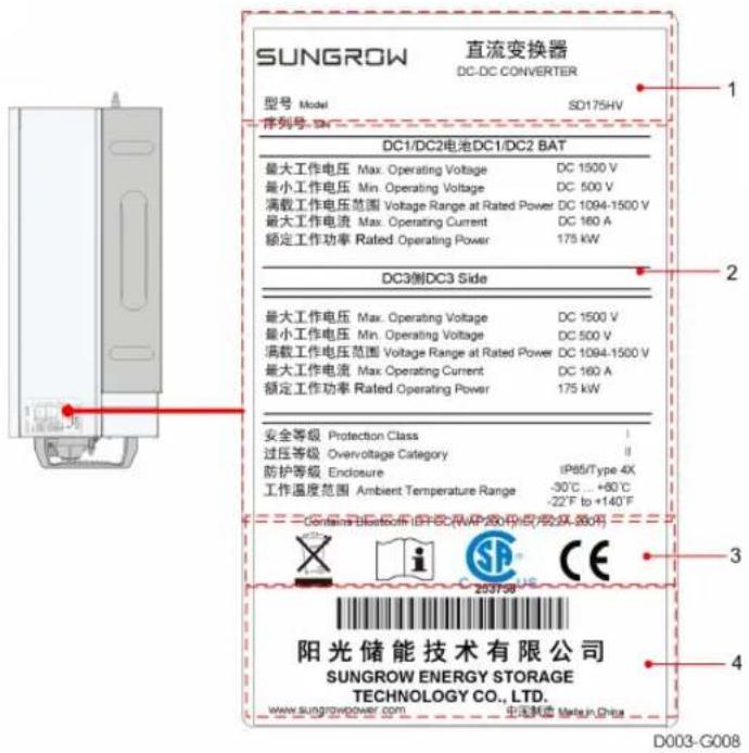
figure 3-1 Nameplate
* The image shown here is for reference only. The actual product you receive may differ.
| Item | Description |
| 1 | SUNGROW logo and product type |
| 2 | Technical data of converter |
| 3 | Instructions and marks of conformity |
| 4 | Company name, website and country of manufacture |
table 3-1 Description of Icons on the Nameplate
| Icon | Description |
 | Do not dispose of the converter together with household waste |
 | Refer to the corresponding instructions |
 | CSA mark of conformity |
 | CE mark of conformity |
3.3 Converter Storage
Store the converter properly when the converter is not to be installed immediately.
- Store the converter in the original packing case with the desiccant inside.
- The storage temperature should be always between -40^ and +70^ , and the storage relative humidity should be always between 0 and 95% , non-condensing.
- In case of stacking storage, the number of stacking layers should never exceed the limit marked on the outer side of the packing case.
- The packing case should be upright.
- If the converter has been stored more than half a year, the qualified personnel should thoroughly check and test it before using.
4 Mechanical Mounting
WARNING
Respect all local standards and requirements during mechanical installation.
4.1 Safety during Mounting
! DANGER
Make sure there is no electrical connection before installation. In order to avoid electric shock or other injury, be sure there is no electricity or plumbing installations before drilling holes.
CAUTION
Risk of pesonal injury due to improper handling operations!
• Always follow the instructions when moving and positioning the converter.
System performance loss due to poor ventilation!
• Operation of the equipment required to ensure good ventilation.
- Keep the heat sinks uncovered to ensure heat dissipation performance.
4.2 Location Selection
4.2.1 Installation Environment Requirements
• The installation environment is free of inflammable or explosive materials.
• The converter should be installed in a place inaccessible to the children.
• The ambient temperature and relative humidity should meet the following requirements.
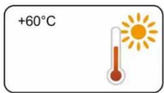
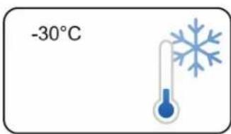
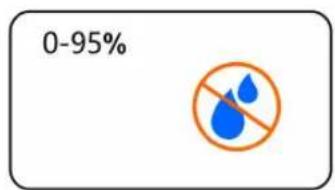
- Do not install the converter outdoors in salt stress areas. Salt stress areas mainly refer to coastal areas that are within 500 meters from the coast. The amount deposited by a salt fog is correlated to the characteristics of the sea water, winds, precipitation, air humidity, topography and forest coverage of adjacent water bodies or sea, and there are substantial differences between different coastal areas.
- The converter should be protected against exposure to direct sunlight, rain, or snow to ensure longer service life.
• The converter should be well ventilated. Ensure air circulation. - The converter should be installed at a location that is at least 30m away from third party wireless communication facilities and populated areas.
4.2.2 Carrier Requirements
The concrete wall should be capable of withstanding a force of four times the weight of the inverter and be suitable for the dimensions of the inverter.
4.2.3 Installation Angle Requirements
It is recommended to install the converter lying flat.
4.2.4 Installation Clearance Requirements
- Reserve enough clearance around the converter to ensure sufficient space for heat dissipation.
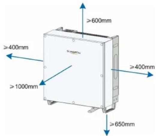
- In case of multiple converters, reserve specific clearance between the converters.

4.3 Installation Tools
Prepare the following tools before installation:
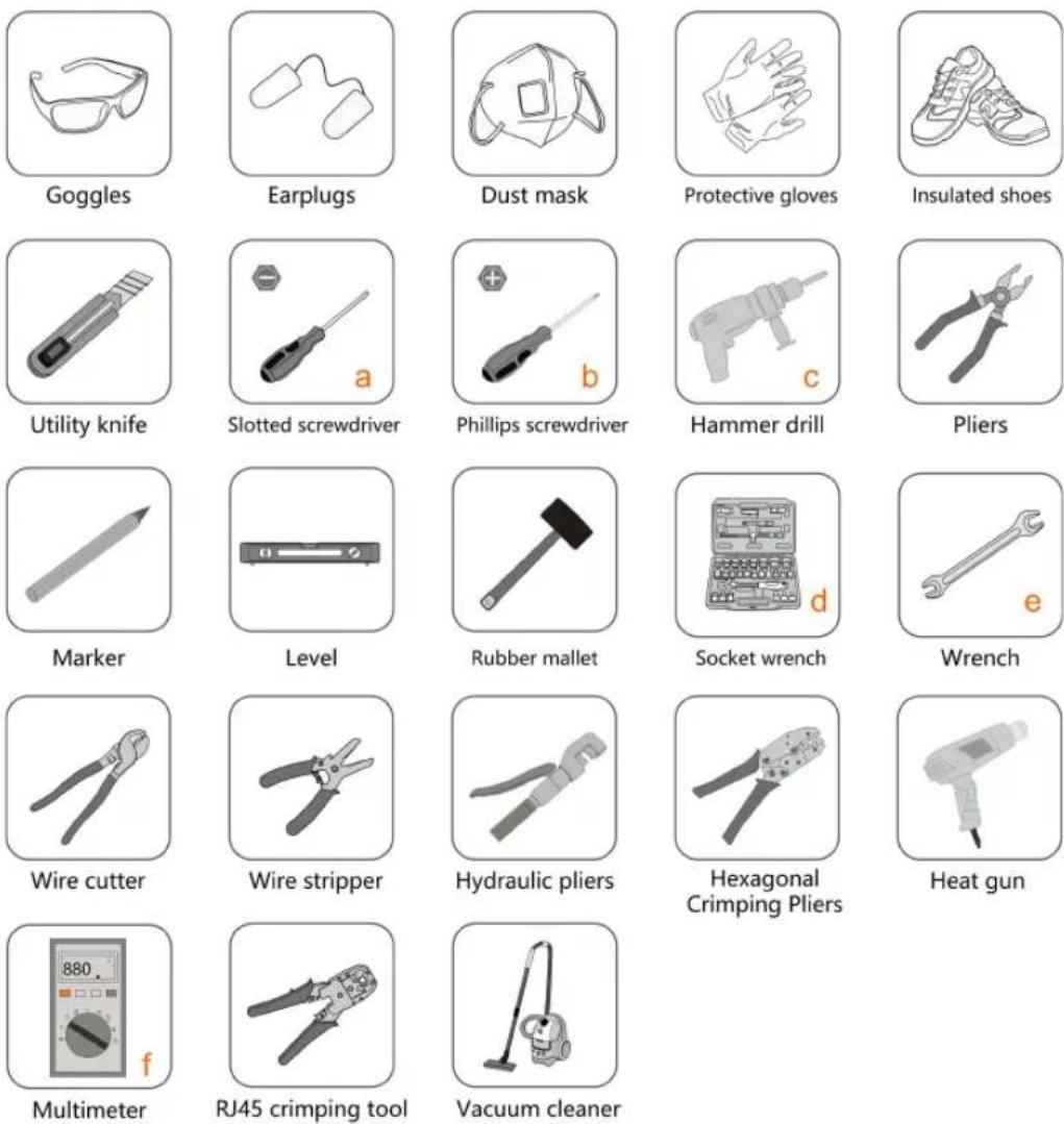
figure 4-1 Installation Tools
| Item | Description |
| a | M2 |
| b M4/M6 | |
| c | Drill bit: φ12、φ14 |
| d Includes sleeve with opening size 16mm | |
| e | Opening:13mm, 16mm |
| f Range≥1500Vdc | |
4.4 Moving the Converter
Move the converter to the specified position before installation. When moving the converter, follow the instructions below.
• Always concerned about the weight of the converter.
- Lift and move the inverter to the destination by using the side handles.
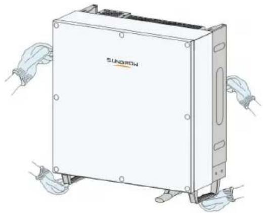
natural_image
Illustration of a SunIORh industrial device with hands adjusting its base (no text or symbols visible)- It is recommended to have two installers move the converter together or use proper tools to move the converter.
- Prevent the converter from tilting or dropping.
CAUTION
Inappropriate moving operation may cause personal injury!
- It is recommended that at least two installers carry the converter together and wear protective equipment such as smash-proof shoes and gloves.
• Always beware of the gravity center of the converter and avoid tipping.
NOTICE
The ground surface on which the converter is to be placed should be covered with a sponge pad, foam cushion or the like to prevent the converter bottom from scratches.
4.5 Preparation before Mounting
Tools
| Item | Specification |
| Phillips screwdriver/ electric screw driver | M4、M6 |
| Marker | - |
| Level | - |
| Hammer drill | Drill bit: φ12 |
| Socket wrench | Including 16mm socket |
| Wrench | Opening: 16mm |
Component parts
| Item Sum | Specification | Source | |
| Phillips screw | 2 M4×10 | Delivery scope | |
| 2 M6×65 | Delivery scope | ||
| Bolt assembly | 4 M10 | Delivery scope | |
5 Electrical Connection
5.1 Safety Instructions
! DANGER
• High voltage may be present inside the converter!
- Do not connect DC circuit breakers before finishing electrical connections.
- Ensure all cables are voltage free before performing cable connection.
WARNING
- Any improper operations during cable connection can cause device damage or personal injury.
- Only qualified personnel can perform cable connection.
- All cables must be undamaged, firmly attached, properly insulated and adequately dimensioned.
NOTICE
- The applicable safety instructions of the storage battery must be observed.
- All electrical connections must be in accordance with local and national standards.
5.2 Terminal Description
Wiring terminals are at the bottom of the converter, as shown in the figure below.
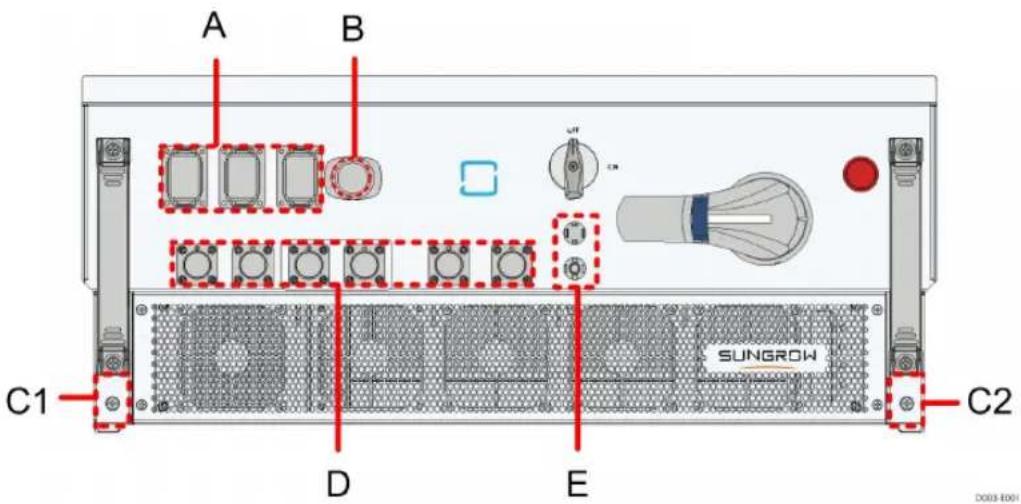
figure 5-1 Wiring terminals
*Image shown here is for reference only. The actual product you receive may differ.
| Item | Terminal Mark Note | ||
| A | Communication terminal | COMM1/COMM2/COMM3 | RS485 communication, and digital input/output DI/DO. |
| B | Ethernet terminal | Ethernet To connect to BMS or router or data collector. | |
| C1 | PE terminal |  | To ground the system protection. Configure multiple PE terminals to facilitate the inter-connection of the grounding points of multiple converters. |
| C2 | |||
| D | DC terminal 1/2/3 | DC1+/DC1-DC2+/DC2- | To connect to the storage battery. |
| DC3+/DC3- To connect to the inverter. | |||
| E | Power supply terminal | 1500V | To supply power to the BMS. |
5.3 Electrical Connection Overview
Electrical connection in the energy storage system includes additional grounding connection, DC connection, and communication connection.
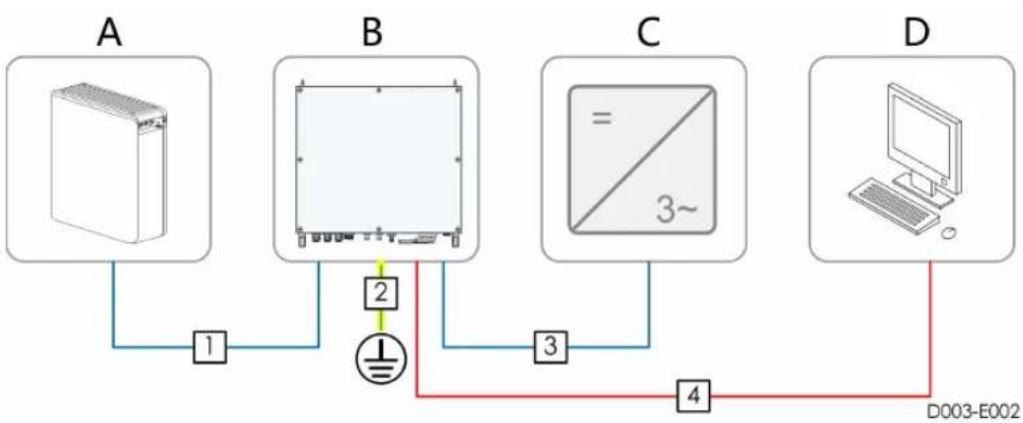
flowchart
graph TD
    A["Device"] -->|1| B["Display Unit"]
    B -->|2| C["3-pin Connector"]
    C -->|3| D["Computer"]
    D -->|4| B
    style A fill:#f9f,stroke:#333
    style B fill:#ccf,stroke:#333
    style C fill:#cfc,stroke:#333
    style D fill:#fcc,stroke:#333
Item Designation
| A Battery | |
| B Converter SD175HV | |
| C | Power conversion equipment such as inverters and battery storage converters |
| D Data collector or SCADA equipment | |
table 5-1 Cable requirements
| No. Cable | Type | Specification | ||
| Outer diameter (mm) | Conductor Cross-section (mm2) | |||
| 1 | DC cable ( DC1/DC2 ) | Outdoor copper cable with 1,500V standard | 12.9~17 50~70 | |
| 2 | Grounding cable | Outdoor copper cable | / 16~35 | |
| 3 DC cable ( DC3 ) | Outdoor copper cable with 1,500V standard | 12.9~17 50~70 | ||
| 4 | Communication cable | Shielded twisted pair | 5.3~7 0.5~1.0 | |
| CAT-5 Ethernet cable | 5.3~7 / | |||
NOTICE
DC3 connects to the DC battery storage terminal of the inverter. The length of the cable is less than 10 meters. Make sure that the cable is straight and flat during on-site installation. Do not twist the cable. Contact Sungrow if the application area is beyond the range.
5.4 Additional Grounding Connection
WARNING
Connect the additional grounding terminal to the protective grounding point before DC cable connection and communication cable connection.
5.4.1 Additional Grounding Requirements
All non-current carrying metal parts and device enclosures in the energy storage system should be grounded, for example, brackets and converter enclosure.
The additional grounding terminal of the single converter requires near-end grounding.
When there are multiple converters, additional grounding terminals of all these converters and grounding points of the brackets should be connected together first and then to an equipotential line, to ensure equipotential connection. Specific operation depends on onsite conditions.
If the area of the grounding cable is greater than 16mm^2, it can be grounded at a single point.
5.4.2 Connection Procedure
step 1 Prepare the cable and OT/DT terminal.
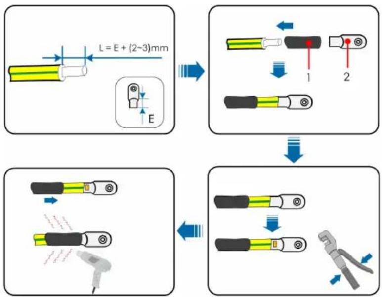
flowchart
graph TD
    A["Length measurement L = E + (2~3)mm"] --> B["Assembly steps 1 and 2"]
    B --> C["Disassembly with clamping tool"]
1 : Heat shrink tubing 2 : OT/DT terminal
step 2 Unscrew the screw on the side of the converter, fasten the cable with a screw driver.
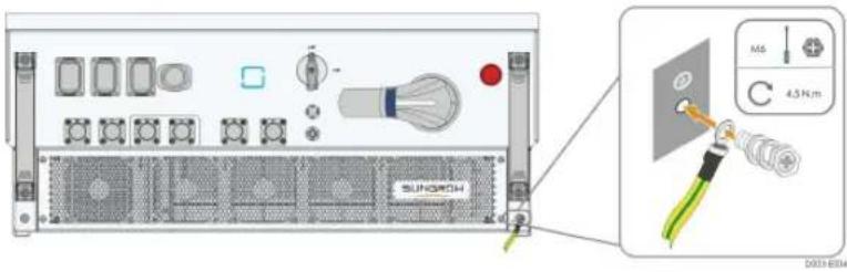
step 3 Apply silica gel or paint the grounding terminal to improve its anti-corrosion performance.

There are two grounding terminals. Use at least one of them to ground the converter.
-- End
5.5 DC Cable Connection
! DANGER
Electric shock!
Be careful when you connect the electrical cables. Voltage that can be fatal may exist between the positive and negative electrodes of the storage battery.
WARNING
Make sure that the battery is well insulated to the ground before you connect the storage battery to the converter.
NOTICE
The following requirements must be fulfilled when the battery is being connected. Failing to do so may cause irreversible damage to the converter that is not covered by the warranty.
- Make sure that the voltage on the positive or negative electrode of the storage batter does not exceed 1,500V.
- Make sure that the maximum input current of the storage battery does not exceed 140A.
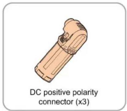
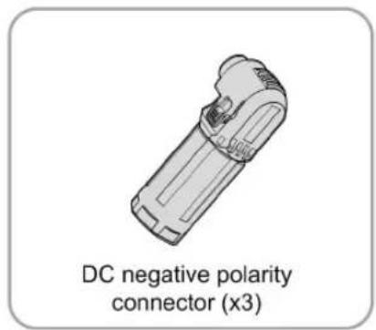
step 1 Take out the DC connector from the packaging. The positive electrode connector is orange and the negative electrode connector is black.
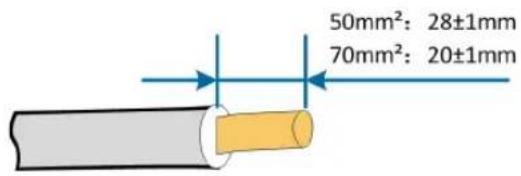
step 2 Strip insulation layers of all DC cables.
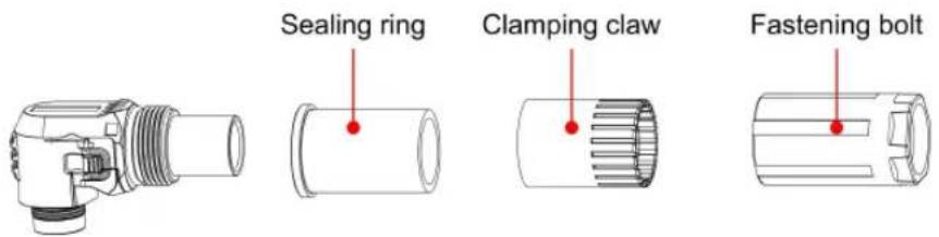
step 3 Dismantle the connector.
step 4 Pass the cable through the nut, clamping claw and sealing ring in that order. Insert the cable end into the base of the connector, and use the hexagonal crimping tool to press it tightly.
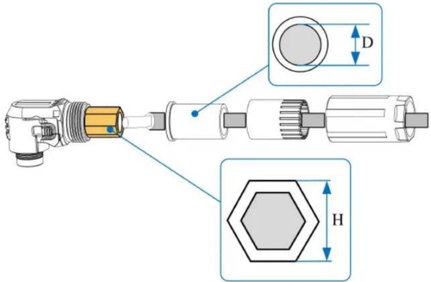
| Code | Name Recommended Value | |
| H | Crimping height | 50mm2: 9.2mm |
| 70mm2: 10.8mm | ||
| Co-de | Name Recommended Value | |
| D | Sealing ring diameter | Choose a sealing ring that is marked 12.9-14.5 to seal the installation if the outer diameter of the cable is 12.9-14.5 mm. |
| Choose a sealing ring that is marked 14.5-16 to seal the installation if the outer diameter of the cable is 14.5-16 mm. | ||
| Choose a sealing ring that is marked 16-17 to seal the installation if the outer diameter of the cable is 16-17 mm. | ||
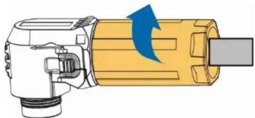
step 5 Put the sealing ring and clamping claw back in order, and screw the nut.
natural_image
Illustration of a mechanical device with a blue arrow indicating rotation or force direction (no text or symbols)step 6 Handle all the converters in order, then press the unlock button on the side of the connector and insert it into the terminal at the base of the converter.
-- End
5.6 PV Connector Connection
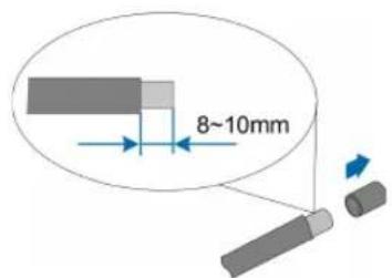
step 1 Strip the insulation layer of the power cable.
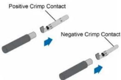
step 2 Assemble the cable ends with the crimping pliers.
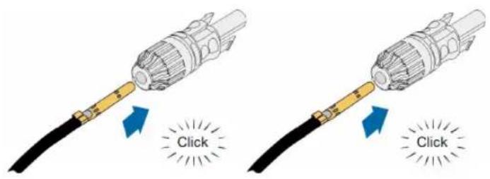
step 3 Lead the cable through the cable gland, and insert it into the insulator until it snaps into place. Gently pull the cable backward to ensure a firm connection. Tighten the cable gland and the insulator with a torque of 2.5 N.m to 3 N.m.
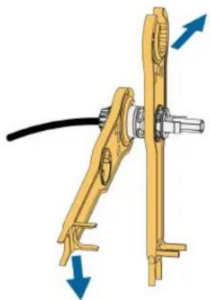
step 4 Screw the nut.
natural_image
Mechanical assembly diagram showing a yellow bracket with blue directional arrows indicating motion (no text or symbols)Cross-sectional area(mm²) Torque(N·m)
44.0
63.5
step 5 Check for polarity correctness.
NOTICE
The converter will not function properly if any PV polarity is reversed.
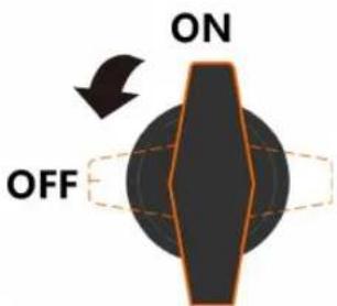
step 6 Turn the auxiliary power switch to the "OFF" position.
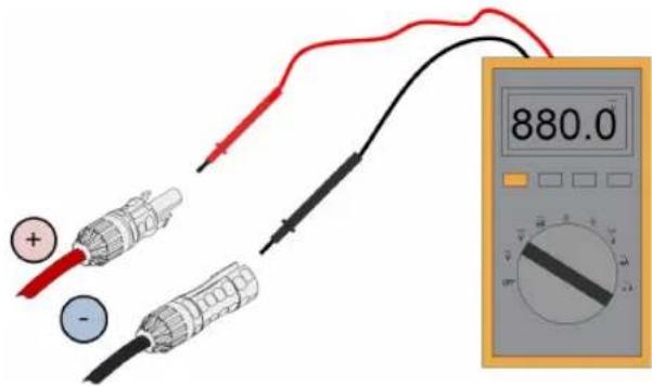
step 7 Check whether the polarity of the cable is correct, and ensure that in any case the open-circuit voltage does not exceed 1500V, the upper limit of the converter input voltage.
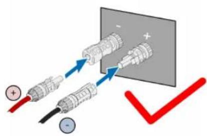
step 8 Connect the PV connectors to corresponding terminals until there is an audible click.
NOTICE
Check the positive and negative polarity of the PV strings, and connect the PV connectors to corresponding terminals only after ensuring polarity correctness.
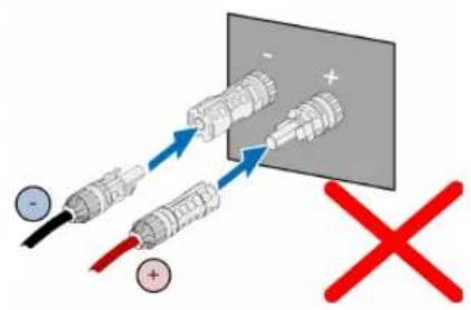
Arc or contactor over-temperature may occur if the PV connectors are not firmly in place, and SUNGROW shall not be held liable for any damage caused.
-- End
5.7 Ethernet Connection

Skip step 1 if there is network cable with a RJ45 connector on site.
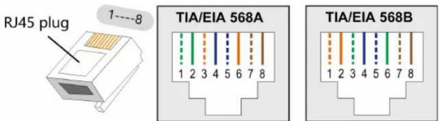
step 1 Strip the insulation layer of the Ethernet cable with a wire stripper, and insert the signal wires to the RJ45 connector. Crimp the RJ45 connector with a crimping tool.
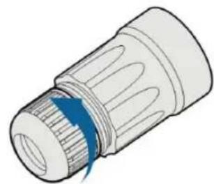
step 2 Unscrew the waterproof nut at the base.
natural_image
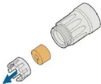
Illustration of a mechanical component with a blue arrow indicating rotation or force (no text or symbols)step 3 Remove the waterproof sealing plug and clamping claws.
natural_image
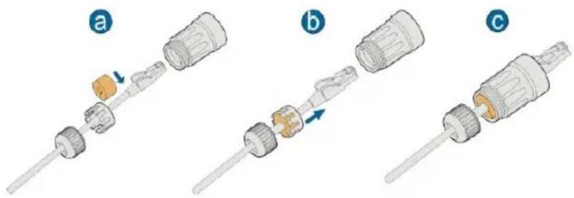
Diagram showing a mechanical component with a blue arrow indicating direction, no text or symbols presentstep 4 Thread the network cable through the waterproof nut, clamping claw and sealing plug, and then tighten the nut.
step 5 Remove the protective cap of the communication terminal and insert the ethernet cable line into it, and screw tight.
-- End
5.8 Communication Connection
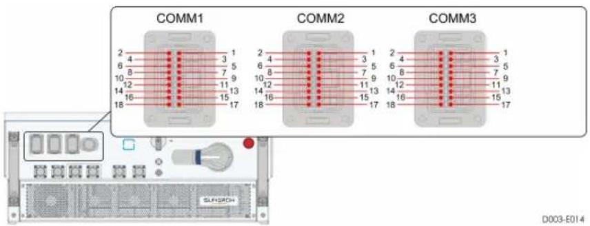
| Code | Signal Definition |
| COMM1-1 PE2 | |
| COMM1-2 | - |
| COMM1-3 | HN_COMHN |
| COMM1-4 | HP_COMHP |
| COMM1-5 | LN_COMLN |
| COMM1-6 | LP_COMLP |
| COMM1-7 | PE2 |
| COMM1-8 | - |
| COMM1-9 | GND_P |
| COMM1-10 | +24V_P |
| COMM1-11 | GND_P |
| COMM1-12 | +24V_P |
| COMM1-13 | PE2 |
| COMM1-14 | HP_COMHP_0 |
| COMM1-15 | HN_COMHN_0 |
| COMM1-16 | PE2 |
| COMM1-17 | LN_COMLN_0 |
| COMM1-18 | LP_COMLP_0 |
| COMM2-1 | BMS_A |
| COMM2-2 | A2 |
| COMM2-3 | BMS_B |
| COMM2-4 | B2 |
| COMM2-5 | DI_1 |
| COMM2-6 | A1 |
| COMM2-7 | PGND_24V |
| COMM2-8 | B1 |
| COMM2-9 | - |
| COMM2-10 | BMS_CANH |
| COMM2-11 | - |
| COMM2-12 | BMS_CANL |
| COMM2-13 | - |
| COMM2-14 | DSP_CANH |
| COMM2-15 | NC1 |
| COMM2-16 | DSP_CANL |
| COMM2-17 | - |
| COMM2-18 | - |
| COMM3-1 | BMS_A |
| COMM3-2 | A2 |
| COMM3-3 | BMS_B |
| COMM3-4 | B2 |
| COMM3-5 | DI_1 |
| COMM3-6 | A1 |
| COMM3-7 | PGND_24V |
| COMM3-8 | B1 |
| COMM3-9 | - |
| COMM3-10 | BMS_CANH |
| COMM3-11 | COM1 |
| COMM3-12 | BMS_CANL |
| COMM3-13 | - |
| COMM3-14 | DSP_CANH |
| COMM3-15 | NO1 |
| COMM3-16 | DSP_CANL |
| COMM3-17 | - |
| COMM3-18 | - |
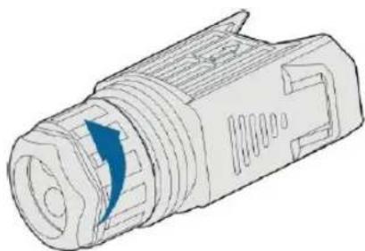
step 1 Unscrew the waterproof nut at the base.
natural_image
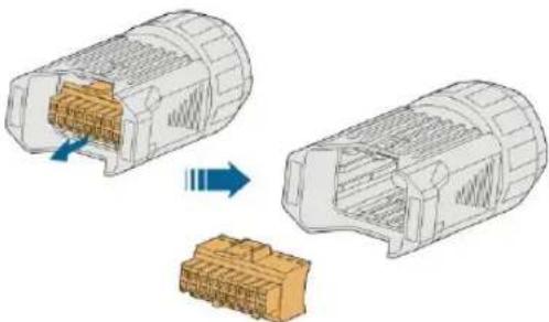
Technical line drawing of a mechanical connector with a blue arrow indicating direction (no text or symbols)step 2 Take out the internal wiring block.
natural_image
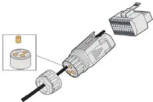
Diagram showing two 3D views of a connector with internal components, one being opened and the other assembled (no text or symbols present)step 3 Remove the waterproof protective cap and thread the network cable.
natural_image
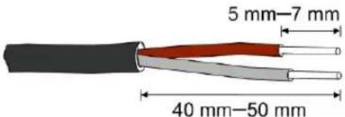
Diagram of a mechanical connector assembly showing internal components and a close-up view of a cylindrical component (no text or symbols present)step 4 Strip the protection layer and insulation layer by appropriate length.
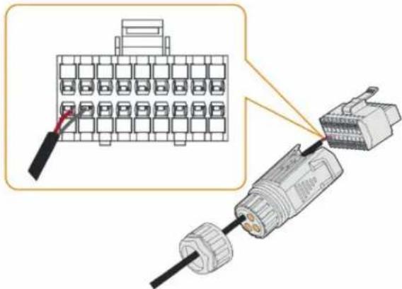
step 5 Thread the connector with the network cable and secure them on the wiring block.
natural_image
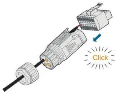
Diagram showing a connector assembly with a grid layout and cable connection (no text or symbols)step 6 Put the wiring block back into the connector.
natural_image
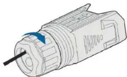
Diagram of a connector with a highlighted cable and a 'Click' button, showing no text or symbols beyond the icon.step 7 Screw the nut.
natural_image
Technical line drawing of a mechanical device with a blue arrow indicating rotation or movement (no text or symbols)step 8 Remove the protective cap of the communication terminal and insert the communication connector.
-- End
6 Commissioning
6.1 Inspection before Commissioning
Check the following items before starting the converter:
- The converter is correctly installed and secure.
• The converter DC switch and external circuit breaker are disconnected. - All cables and auxiliary parts are properly connected and fastened.
- The cables are routed in a safe place or protected against mechanical damage.
- All unused terminals at the bottom of the converter are properly sealed.
- No external objects or parts are left on the top of the converter.
- Warning signs & labels are suitably affixed and durable.
6.2 Commissioning Procedure
step 1 Rotate all the DC switches of the converter to "ON" position.
step 2 Connect the DC switch (if applicable) between the converter and the front and rear equipment.
step 3 If it is normal and the input conditions meet requirements, the converter will normally operate.
step 4 Observe the LED indicator to ensure that the converter operates normally. (Refer to "LED Indicator Panel").
-- End
7 iSolarCloud APP
7.1 Brief Introduction
The iSolarCloud APP can establish communication connection to the converter via the Bluetooth, thereby achieving near-end maintenance on the converter. Users can use the APP to view basic information, alarms, and events, set parameters, or download logs, etc.
*In case the communication module Eye or WiFi is available, the iSolarCloud APP can also establish communication connection to the converter via the mobile data or WiFi, thereby achieving remote maintenance on the converter.

- This manual describes only how to achieve near-end maintenance via the Bluetooth connection. For remote maintenance through the Eye or WiFi, refer to the related manuals in the delivery scope.
- Screenshots in this manual are based on the Android system V2.1.6.20200422, and the actual interfaces may differ.
7.2 Download and Install
Method 1
- MyApp (Android, mainland China users)
- Google Play (Android, users other than mainland China ones)
- APP store (iOS)
Method 2
Scan the following QR code to download and install the APP according to the prompt information.

The APP icon appears on the home screen after installation.

natural_image
Simple icon of a white cloud with rays on an orange background (no text or symbols)7.3 Login
7.3.1 Requirements
The following items should meet requirements:
• The DC sides of the converter is powered-on.
- The mobile phone is within 5m away from the converter and there are no obstructions in between.
• The Bluetooth function of the mobile phone is enabled.
7.3.2 Login Steps
step 1 Open the APP to enter the login interface, and click "Direct Login" to enter the next screen.
step 2 Open the APP, after which the Bluetooth search screen pops up automatically, and select the to-be-connected converter according the SN on the nameplate of the converter. The Bluetooth indicator is on once the connection is established. Alternatively, tap “☐” to scan the QR code on the side of the converter to establish Bluetooth connection.
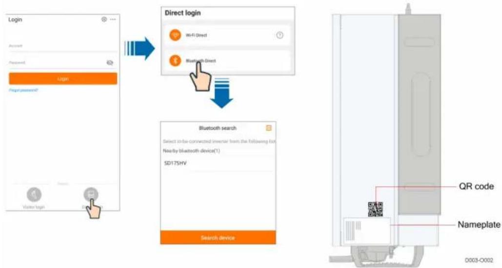
flowchart
graph TD
    A["Login"] --> B["Direct login"]
    B --> C["Bluetooth search"]
    C --> D["QR code"]
    C --> E["Nameplate"]
figure 7-1 Bluetooth connection
step 3 Enter the login screen after the Bluetooth connection is established.
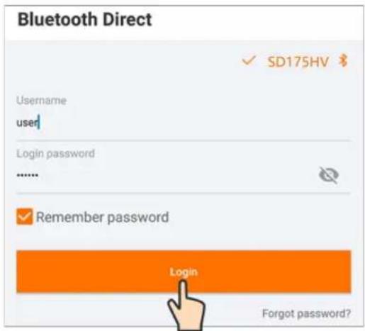
figure 7-2 Login
i
- Username is "user", initial password is "pw1111". Change the initial password for account security.
- To set converter parameters related to grid protection and grid support, contact SUNGROW to obtain the advanced account and corresponding password.
-- End
7.4 Home page
After login, the home page is as "figure 7-3 Home page".
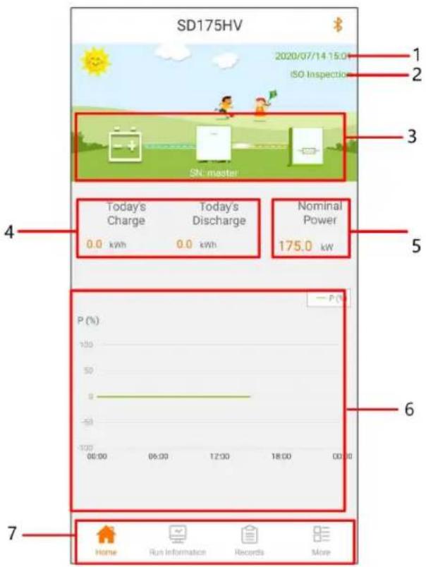
figure 7-3 Home page
table 7-1 Home page description
| No. | Designation | Description |
| 1 | Date and time | System date and time of the converter |
| 2 | Converter state | Present operation state of the converter For details, refer to"table 7-2 Description of converter state". |
| 3 | Power flow chart | Displays information such as photovoltaic power capacity and on-grid power. Arrows between the icons show the flow of energy between the devices. The direction of the arrows indicates the direction of energy flow. |
| 4 | Power generation | Displays the power generated and discharge volume of the converter for today. |
| 5 Power | Displays the rated power of the converter. | |
| 6 Power curve | Displays the daily power trend curve.(Each point on the curve represents the ratio of the current power to the rated power of the converter). | |
| 7 | Navigation bar | Including "Home", "Run-information", "History-record", and "More" |
table 7-2 Description of converter state
| State | Description |
| Initial standby | The converter continuously tests the photovoltaic array and grid to check that they meet the operating requirements for parallel-in. When the conditions for grid-connection are met, the converter switches from the "initial standby" mode to the "starting" mode. |
| ISO testing | Converter tests the insulation resistance before it starts conversion. |
| Starting | A temporary transitional process during which the converter switches from the "initial standby" mode to "operation" mode. When this mode ends, the converter is ready to parallel in and supply power. |
| Running Converter is running smoothly. | |
| Running with alarm | Converter is still running but alarm signals are sent. |
| Derated operation | Converter is affected by some external factors such as temperature and power grid voltage and running at derated power. |
| Hot standby | Converter is running with zero power. |
| On/Off button | Converter is turned off by the app and enters the off-state. |
| Fault stop Converter detects a fault and stops running. | |
| Emergency stop | Shutdown triggered by the external emergency stop signal. |
If the converter is running abnormally, the alarm or fault icon ✗ will be displayed in the lower right corner of the converter icon in power flow chart. The user can tap this icon to enter the alarm or fault screen to view detailed information and corrective measures.
7.5 Running Information
Tap"Running Information" on the navigation bar to enter the running information screen, as shown in "figure 7-4 Running Information".
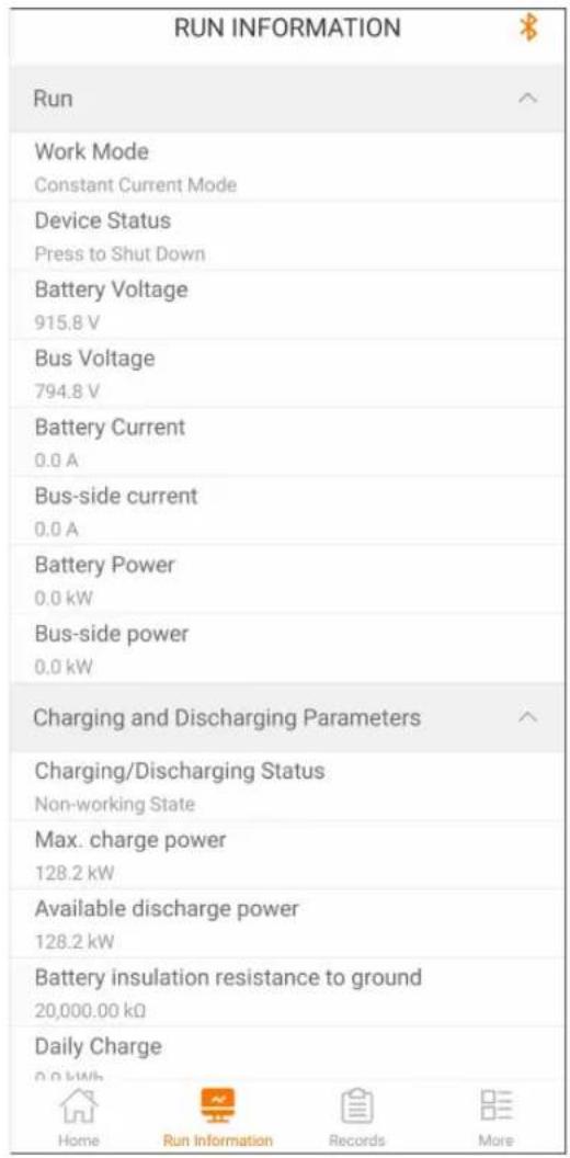
figure 7-4 Running Information
Run information includes information on running, charging and discharging parameters, environment, and battery.
7.6 History Record
Tap "History Record" on the navigation bar to enter the history record screen, as shown in "figure 7-5 History record".
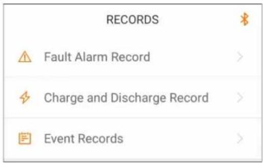
figure 7-5 History record
The user can view faults and alarm records, charging and discharging records, and events from "Records".
7.6.1 Fault Alarm Records
Tap" Fault Alarm Records" to view fault and alarm records, as shown in "figure 7-6 Fault and alarm records".
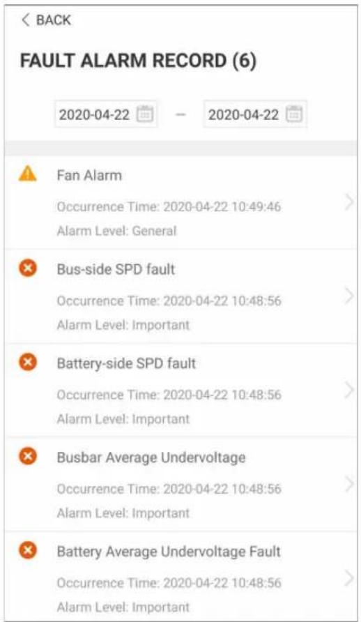
figure 7-6 Fault and alarm records

- Click“” to select a time segment and view corresponding records.
• The converter can record up to 400 latest entries.
Select one of the records in the list and click the record, to view the detailed fault info as shown in "figure 7-7 Detailed fault alarm information";
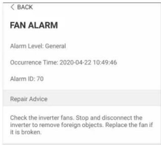
figure 7-7 Detailed fault alarm information
7.6.2 Power Yields Records
User can view various energy records: power curve, daily energy histogram, daily energy histogram, monthly energy histogram, and annual energy histogram.
table 7-3 Explanation of power yields records
| Parameter | Description |
| Power curve | Show the power output every day. Each point in the curve is the percentage of present power and nominal power. |
| Daily energy histogram | Shows the power output every day in the present month. View the monthly power generated for the last 12 months. |
| Monthly energy histogram | Shows the power output every month in a year. View the annual power generated for the last 25 years. |
| Annual energy histogram | Shows the power output every year. View the annual power generated for the last 25 years. |
step 1 Click the "Charge and Discharge Record" to view the power curve page as shown in "figure 7-8 Power curve";
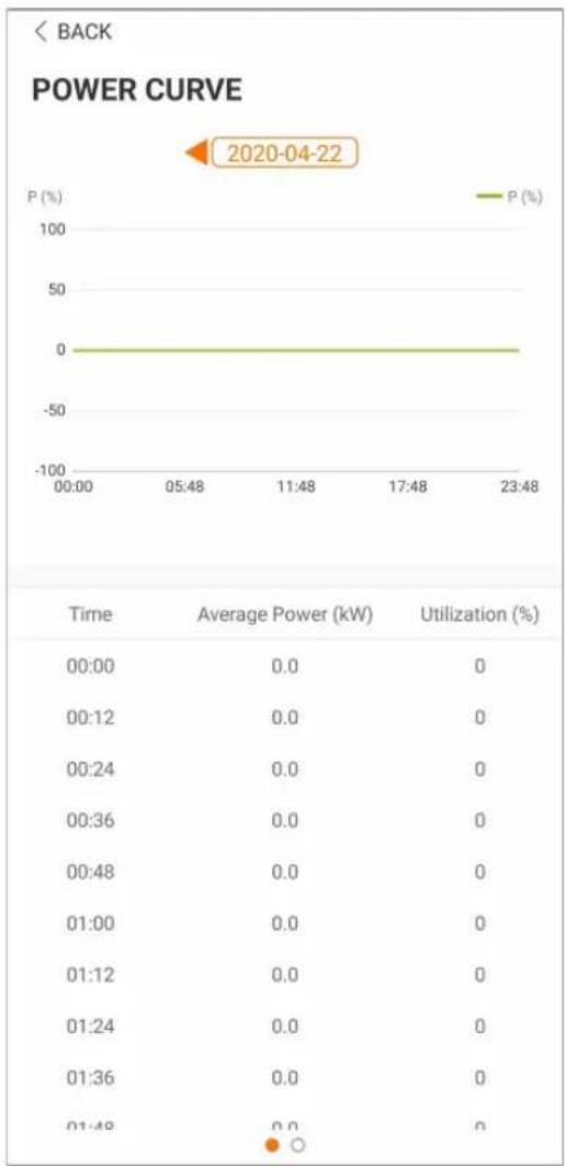
line
| Time | Average Power (kW) | Utilization (%) | |--------|--------------------|-----------------| | 00:00 | 0.0 | 0 | | 00:12 | 0.0 | 0 | | 00:24 | 0.0 | 0 | | 00:36 | 0.0 | 0 | | 00:48 | 0.0 | 0 | | 01:00 | 0.0 | 0 | | 01:12 | 0.0 | 0 | | 01:24 | 0.0 | 0 | | 01:36 | 0.0 | 0 | | 01:48 | 0.0 | 0 |figure 7-8 Power curve
step 2 Tap the time bar on the top of the screen to select a time segment and view the corresponding power curve.
step 3 Swipe left to check the power yields histogram.
-- End
7.6.3 Event Records
Click"Event Records" to view event record list.

- Click“ ” to select a time segment and view corresponding event records.
• The converter can at most record the latest 400 events.
7.7 More
Tap"More "on the navigation bar to enter the "More" screen, as shown in "figure 7-9 More".
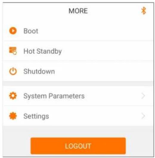
figure 7-9 More
7.7.1 Boot
step 1 Click"Boot" to go to the boot-up page, as shown in "figure 7-10 Boot".
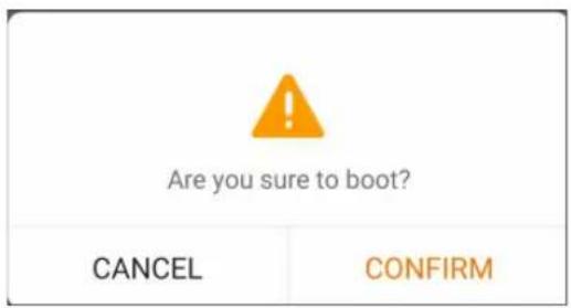
figure 7-10 Boot
step 2 Click "CONFIRM" to boot.
-- End
7.7.2 Hot Standby
step 1 Click"Hot Standby "to go to the hot standby page as shown in"figure 7-11 Hot Standby".
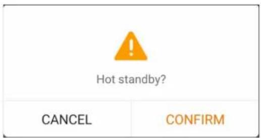
figure 7-11 Hot Standby
step 2 Click "CONFIRM" to initiate hot standby.
-- End
7.7.3 Shutdown
step 1 Click" Shutdown" to go to the hot standby page as shown in "figure 7-12 Shutdown".
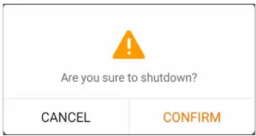
figure 7-12 Shutdown
step 2 Click "CONFIRM" to shut down.
-- End
7.7.4 System Parameters
Click "System Parameters" to go to the parameter configuration page as shown in "figure 7-13 System Parameters". Change the equipment model and software version on this page.
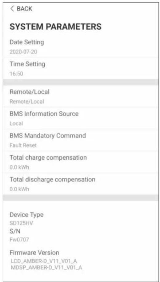
figure 7-13 System Parameters
7.7.5 Settings
Click "Settings" to go to the parameter configuration page as shown in "figure 7-14 Settings". Change the operation parameters, protection parameters, and communication parameters on this page.
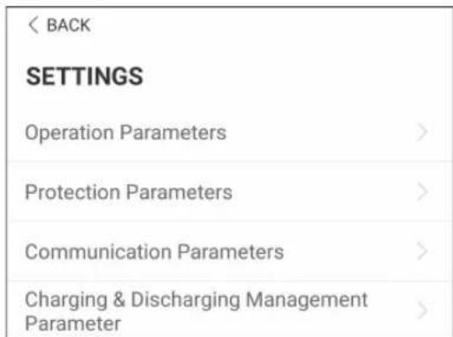
figure 7-14 Settings
table 7-4 Parameter Settings Description
| Parameter | Range | Default value |
| System Parameters | ||
| System Time : Y | 2000~2099 2000 | |
| System Time : M | 1~12 1 | |
| System Time : D | 1~31 1 | |
| System Time : H | 0~23 0 | |
| System Time : Min | 0~59 0 | |
| System Time : S | 0~59 0 | |
| Boot/Shutdown/Hot Standby Off/On/Hot Standby Off | ||
| Remote/Local Remote/Local/Remote & Local Remote & Local | ||
| BMS Information Source | Local/EMS/Battery Local | |
| BMS Mandatory Command | Close/Open/Fault Reset/No Operation | Fault Reset |
| Total charge compensation ( kWh ) | -20000000~20000000 0 | |
| Total discharge compensation (kWh) | -20000000~20000000 0 | |
| Historical Record Storage Period | 15 minutes/10 minutes/5 minutes | 15 minutes |
| Export Recording Data | 0xAA: Enable / | |
| Operation Parameters->General Parameters | ||
| Set working mode | Constant Current/Constant Voltage/Constant Power/MPPT/Constant Bus Voltage | Constant Current |
| CC current value(A) | -160~160 0 | |
| CV voltage value(V) | 0~1500 800 | |
| CV limiting current(A) | 0~160 0 | |
| Constant power value(%) | -100~100 0 | |
| Parallel Communication Address 1~16 1 | ||
| Master-slave setting Master/Slave Master | ||
| Enable Parallel Operation Enable/Disable Disable | ||
| Enable DC coupling Enable/Disable Disable | ||
| Active Soft Start Enable/Disable Enable | ||
| Active Rising Slope(%/s) | 1~2000 500 | |
| Active Decline Slope(%/s) | 1~2000 500 | |
| Auto Fault Recovery Enable/Disable | Enable | |
| Reconnecting Time(s) | 1~600 20 | |
| Bus-side constant voltage value (V) | 0~1550 1000 | |
| Enable voltage droop control | Enable/Disable Disable | |
| Voltage droop factor(%) | 1~20 5 | |
| Operation Parameters->Charging and Discharging Parameters | ||
| Max. battery Charge voltage(V) | 0~1500 1300 | |
| Min. battery Discharge voltage (V) | 0~1500 580 | |
| Max. battery charge current(A) | 0~160 160 | |
| Max. battery discharge current (A) | 0~160 160 | |
| Operation Parameters->SOC Parameter | ||
| Battery Charge SOC Upper Limit (%) | 0~100 95 | |
| Battery Discharge SOC Lower Limit(%) | 0~99.9 5 | |
| SOC balancing Enable/Disable Disable | ||
| SOC balancing power(%) | 0~100 20 | |
| SOC Balance Control Mode Local Control Mode/Remote Control Mode | Local Control Mode | |
| Protection Parameter->Battery Parameters | ||
| Battery overvoltage recovery value(V) | 2~1499.9 1450 | |
| Battery undervoltage recovery value(V) | 1~1499.8 550 | |
| Battery overvoltage level-1 protection value(V) | 0.3~1500 1500 | |
| Battery overvoltage level-2 protection value(V) | 0.3~1500 1500 | |
| Battery overvoltage level-3 protection value(V) | 0.3~1500 1500 | |
| Battery undervoltage level-1 protection value(V) | 0~1499.7 500 | |
| Battery undervoltage level-2 protection value(V) | 0~1499.7 500 | |
| Battery undervoltage level-3 protection value(V) | 0~1499.7 500 | |
| Battery overvoltage level-1 protection time(s) | 0.02~300 1 | |
| Battery overvoltage level-2 protection time(s) | 0.02~300 0.1 | |
| Battery overvoltage level-3 protection time(s) | 0.02~300 0.1 | |
| Battery undervoltage level-1 protection time(s) | 0.02~300 1 | |
| Battery undervoltage level-2 protection time(s) | 0.02~300 0.1 | |
| Battery undervoltage level-3 protection time(s) | 0.02~300 0.1 | |
| Protection Parameter->PV Parameter | ||
| Bus-side overvoltage recovery value(V) | 0.2~1499.9 1450 | |
| Bus-side undervoltage recovery value(V) | 0.1~1499.8 550 | |
| Bus-side overvoltage level-1 protection value(V)* | 0.3~1550 1500 | |
| Bus-side overvoltage level-2 protection value(V) | 0.3~1550 1500 | |
| Bus-side overvoltage level-3 protection value(V) | 0.3~1550 1500 | |
| Bus-side undervoltage level-1 protection value(V)* | 0~1499.7 500 | |
| Bus-side undervoltage level-2 protection value(V) | 0~1499.7 500 | |
| Bus-side undervoltage level-3 protection value(V) | 0~1499.7 500 | |
| Bus-side overvoltage level-1 protection time(s) | 0.02~300 1 | |
| Bus-side overvoltage level-2 protection time(s) | 0.02~300 0.1 | |
| Bus-side overvoltage level-3 protection time(s) | 0.02~300 0.1 | |
| Bus-side undervoltage level-1 protection time(s) | 0.02~300 1 | |
| Bus-side undervoltage level-2 protection time(s) | 0.02~300 0.1 | |
| Bus-side undervoltage level-3 protection time(s) | 0.02~300 0.1 | |
| Charging & Discharging Management Parameter | ||
| Timing Charge & Discharge Management | Enable/Disable Disable | |
| Start time 1: hour 0~23 0 | ||
| Start time 1: minute 0~59 0 | ||
| End time 1: hour 0~23 0 | ||
| End time 1: minute 0~59 0 | ||
| Work Mode 1 Not Operated/Charge/Discharge | Not Operated | |
| Preset constant power value 1 | 0~100 0 | |
| Start time 2: hour 0~23 0 | ||
| Start time 2: minute 0~59 0 | ||
| End time 2: hour 0~23 0 | ||
| End time 2: minute 0~59 0 | ||
| Work Mode 2 Not Operated/Charge/Discharge | Not Operated | |
| Preset constant power value 2 | 0~100 0 | |
| Start time 3: hour 0~23 0 | ||
| Start time 3: minute 0~59 0 | ||
| End time 3: hour 0~23 0 | ||
| End time 3: minute 0~59 0 | ||
| Work Mode 3 Not Operated/Charge/Discharge | Not Operated | |
| Preset constant power value 3 | 0~100 0 | |
| Start time 4: hour 0~23 0 | ||
| Start time 4: minute 0~59 0 | ||
| End time 4: hour 0~23 0 | ||
| End time 4: minute 0~59 0 | ||
| Work Mode 4 Not Operated/Charge/Discharge | Not Operated | |
| Preset constant power value 4 | 0~100 0 | |
| Start time 5: hour 0~23 0 | ||
| Start time 5: minute 0~59 0 | ||
| End time 5: hour 0~23 0 | ||
| End time 5: minute 0~59 0 | ||
| Work Mode 5 Not Operated/Charge/Discharge | Not Operated | |
| Preset constant power value 5 | 0~100 0 | |
| Start time 6: hour 0~23 0 | ||
| Start time 6: minute 0~59 0 | ||
| End time 6: hour 0~23 0 | ||
| End time 6: minute 0~59 0 | ||
| Work Mode 6 Not Operated/Charge/Discharge | Not Operated | |
| Preset constant power value 6 | 0~100 0 | |
| Start time 7: hour 0~23 0 | ||
| Start time 7: minute 0~59 0 | ||
| End time 7: hour 0~23 0 | ||
| End time 7: minute 0~59 0 | ||
| Work Mode 7 Not Operated/Charge/Discharge | Not Operated | |
| Preset constant power value 7 | 0~100 0 | |
| Start time 8: hour 0~23 0 | ||
| Start time 8: minute 0~59 0 | ||
| End time 8: hour 0~23 0 | ||
| End time 8: minute 0~59 0 | ||
| Work Mode 8 Not Operated/Charge/Discharge | Not Operated | |
| Preset constant power value 8 | 0~100 0 | |
| Start time 9: hour 0~23 0 | ||
| Start time 9: minute 0~59 0 | ||
| End time 9: hour 0~23 0 | ||
| End time 9: minute 0~59 0 | ||
| Work Mode 9 Not Operated/Charge/Discharge | Not Operated | |
| Preset constant power value 9 | 0~100 0 | |
| Start time 10: hour 0~23 0 | ||
| Start time 10: minute 0~59 0 | ||
| End time 10: hour 0~23 0 | ||
| End time 10: minute 0~59 0 | ||
| Work Mode 10 Not Operated/Charge/Discharge | Not Operated | |
| Preset constant power value 10 | 0~100 0 | |
| Communication Parameters | ||
| BMS Communication Address 1~247 1 | ||
| RS485 port | RS485-1/RS485-2/RS485-3** RS485-1 | |
| IP Address 1 0~255 192 | ||
| IP Address 2 0~255 168 | ||
| IP Address 3 0~255 1 | ||
| IP Address 4 0~255 100 | ||
| Gateway 1 | 0~255 192 | |
| Gateway 2 | 0~255 168 | |
| Gateway 3 | 0~255 1 | |
| Gateway 4 | 0~255 10 | |
| Subnet Mask 1 0~255 255 | ||
| Subnet Mask 2 0~255 255 | ||
| Subnet Mask 3 0~255 0 | ||
| Subnet Mask 4 0~255 0 | ||
| DHCP On/Off On | ||
| Preferred DNS server 1 | 0~255 1 | |
| Preferred DNS server 2 | 0~255 2 | |
| Preferred DNS server 3 | 0~255 4 | |
| Preferred DNS server 4 | 0~255 8 | |
| Alternate DNS server 1 | 0~255 8 | |
| Alternate DNS server 2 | 0~255 8 | |
| Alternate DNS server 3 0~255 8 | ||
| Alternate DNS server 4 0~255 8 | ||
*In Constant Voltage mode, the bus side bus-Overvoltage protection time cannot be set, and the overvoltage protection time in other modes can be used normally.
**RS485-3: Reserved.
8 System Decommissioning
8.1 Disconnecting the Converter
For maintenance or other service work, the converter must be switched off.
Please follow the instructions below to disconnect the converter and DC power supply. Failure to do so may lead to equipment damage or result in death or injury.
step 1 Disconnect the external DC breaker and spin the DC switch of the converter to "OFF".
step 2 Wait for at least 5 minutes for the internal capacitors to be completely discharged.
step 3 Use a current clamp to test the DC cable and confirm that there is no current.
step 4 Dismantle the DC connector.
step 5 Dismantle the Ethernet and communication connector.
step 6 Install waterproof plugs for all the terminals.
-- End
8.2 Dismantling the Converter
Refer to "Mechanical Mounting" and "Electrical Connection" to dismantle the converter in reverse steps.
CAUTION
Risk of burns and electric shock!
Do not touch any inner live parts until at least 10 minutes after disconnecting the converter from the downstream equipment.
NOTICE
If the converter will be reinstalled in the future, store it properly by referring to "Converter Storage".
8.3 Disposal of the Converter
Users take the responsibility for the disposal of the converter.
NOTICE
The battery, module and other components in the converter may pollute the environment. Dispose them in accordance with the applicable rules and regulations.
9 Troubleshooting and Maintenance
9.1 Troubleshooting
Once a fault occurs in the converter, the fault information is displayed on the App interface. See the table below for detailed fault information.
| Fault code | Fault type | Corrective measures |
| 12 | Excessively High Ambient Temperature | Generally, the converter will recover and resume operation when the internal or module temperature is restored back to normal condition. If the fault persists:1. Check whether the ambient temperature of the converter is too high;2. Check whether the converter is in a well-ventilated place;3. Check whether the converter is exposed to direct sunlight.Shield it if so;4. Check whether the fan is running properly. Replace the fan if not;5. If the fault is not caused by the foregoing reasons and still exists, please contact Customer Service of Sungrow Energy Storage Technology Co., Ltd. |
| 22 | BMS Commu-nication Fault | Check whether the communication cable is connected cor-rectly. If the fault persists, please contact Customer Service of Sungrow Energy Storage Technology Co., Ltd. |
| 23 | Reversed Polarity | Check to make sure that the DC side wiring is correct. |
| 24 | Battery Alarm | Please contact the after-sales service center of the battery manufacturer. |
| 25 | Battery Fault | Please contact the after-sales service center of the battery manufacturer. |
| 63 | System Alarm | Please contact Customer Service of Sungrow Energy Storage Technology Co., Ltd. |
| 64 | System Fault | Please contact Customer Service of Sungrow Energy Storage Technology Co., Ltd. |
9.2 Maintenance
! WARNING
Risk of converter damage or personal injury due to incorrect service! Before any service work, observe the following procedure.
- Wait for at least 5 minutes until all electricity has been discharged from the internal battery storage components before any maintenance or repair work is carried out inside the equipment.
- Use testing equipment to make sure that there is no voltage or current.
CAUTION
When performing electrical connection and maintenance work, temporary warning signs or barriers must be posted to prevent unrelated persons from entering the electrical connection or maintenance area.
NOTICE
Do not reboot the converter until all faults that may affect the safety of the converter operations are cleared.
The converter does not contain any part that require maintenance. Do not change the internal components of the converter unless you are authorized to do so. If you need any maintenance service, please contact Sungrow Power After-Sales Service Center. Otherwise Sungrow Power shall not provide any warranty or be held liable for any losses due to such negligence.
Do not touch the printed circuit board or other electrostatic sensitive components as you may damage the device.
- Do not touch the circuit board unnecessarily.
- Observe the regulations to protect against electrostatic and wear an anti-static wrist strap.
Routine Maintenance
| Item Method Method | ||
| System clean | Check the temperature and dust of the converter. Clean the converter enclosure if necessary.Check if the air inlet and outlet are normal.Clean the air inlet and outlet, if necessary. | Six months to a year (depend on the dust contents in air.) |
| Cable entry | Check whether the cable entry is insufficiently sealed or the gap is excessively large, and re-seal the entry when necessary. | Once a year |
| Electrical Connection | Check whether all cable are firmly in place.Check whether a cable is damaged, especially the part contacting the metal enclosure. | Six months to a year |
10 Appendix
10.1 Technical Data
| Parameters | |
| Power | |
| Rated power | 175kW |
| Battery | |
| Maximum DC voltage | 1500V |
| Working voltage range | 500~1500V |
| Maximum DC current 160A | |
| Bus | |
| Maximum DC voltage | 1500V |
| Working voltage range | 500~1500V |
| Maximum DC current 160A | |
| Protection | |
| DC reverse connection protection | Yes |
| Surge protection | Class II |
| Insulation testing | Yes |
| Over-temperature protection | Yes |
| General Data | |
| Dimensions (W*H*D) | 720 * 720 * 300mm |
| Weight 75kg | |
| Ingress protection rating | IP 65 NEMA 4X |
| Operating ambient temperature range | -30 to 60 °C -22 to 140 °F |
| Allowable relative humidity range (non-condensing) | 0 - 95% |
| Cooling method Smart forced-air cooling | |
| Max. operating altitude 4000m (>3000m derating) | |
| Display | LED, Bluetooth + APP |
Parameters
Communication RS485, Ethernet, CAN
Compliance
CE, IEC 62109-1, UL 1741
10.2 Quality Assurance
When product faults occur during the warranty period, SUNGROW will provide free service or replace the product with a new one.
Evidence
During the warranty period, the customer shall provide the product purchase invoice and date. In addition, the trademark on the product shall be undamaged and legible. Otherwise, SUNGROW has the right to refuse to honor the quality guarantee.
Conditions
• After replacement, unqualified products shall be processed by SUNGROW.
- The customer shall give SUNGROW a reasonable period to repair the faulty device.
Exclusion of Liability
In the following circumstances, SUNGROW has the right to refuse to honor the quality guarantee:
- The free warranty period for the whole machine/components has expired.
• The device is damaged during transport. - The device is incorrectly installed, refitted, or used.
- The device operates in harsh conditions beyond those described in this manual.
- The fault or damage is caused by installation, repairs, modification, or disassembly performed by a service provider or personnel not from SUNGROW.
- The fault or damage is caused by the use of non-standard or non-SUNGROW components or software.
- The installation and use range are beyond stipulations of relevant international standards.
- The damage is caused by unexpected natural factors.
For faulty products in any of above cases, if the customer requests maintenance, paid maintenance service may be provided based on the judgment of SUNGROW.
10.3 Contact Information
In case of questions about this product, please contact us.
We need the following information to provide you the best assistance:
- Model of the device
- Serial number of the device
- Fault code/name
- Brief description of the problem
For detailed contact information, please visit: https://en.sungrowpower.com/contactUS
- All Rights Reserved
- Trademarks
- Software Licenses
- About This Manual
- Validity
- Target Group
- How to Use This Manual
- Symbols
- ! DANGER
- WARNING
- CAUTION
- NOTICE
- Contents
- All Rights Reserved ....I
- About This Manual....II
- Safety ....1
- Product Description ....4
- Unpacking and Storage 11
- Mechanical Mounting ....14
- Electrical Connection .... 19
- Commissioning ....33
- iSolarCloud APP ....34
- System Decommissioning ....54
- Troubleshooting and Maintenance ....56
- Appendix 59
- Safety
- Storage Battery
- Converter
- Electric shock risk!
- Skills of Qualified Personnel
- Product Description
- Function Description
- Intended Usage 1
- Intended Usage 2
- Product Introduction
- Type Description
- Appearance
- Dimensions and Weight
- LED Indicator Panel
- DC Switch
- ! WARNING
- Emergency Stop Button
- Circuit Diagram
- Function Description
- Conversion
- Data storage and display
- Parameter configuration
- Communication interface
- Protection
- Unpacking and Storage
- Unpacking and Inspection
- Identifying the Converter
- Converter Storage
- Mechanical Mounting
- Safety during Mounting
- Location Selection
- Installation Environment Requirements
- Carrier Requirements
- Installation Angle Requirements
- Installation Clearance Requirements
- Installation Tools
- Moving the Converter
- Preparation before Mounting
- Electrical Connection
- Safety Instructions
- Terminal Description
- Electrical Connection Overview
- Additional Grounding Connection
- Additional Grounding Requirements
- Connection Procedure
- DC Cable Connection
- PV Connector Connection
- Ethernet Connection
- Communication Connection
- Commissioning
- Inspection before Commissioning
- Commissioning Procedure
- iSolarCloud APP
- Brief Introduction
- Download and Install
- Method 1
- Method 2
- Login
- Requirements
- Login Steps
- i
- Home page
- Running Information
- History Record
- Fault Alarm Records
- Power Yields Records
- Event Records
- More
- Boot
- Hot Standby
- Shutdown
- System Parameters
- Settings
- System Decommissioning
- Disconnecting the Converter
- Dismantling the Converter
- Disposal of the Converter
- Troubleshooting and Maintenance
- Troubleshooting
- Maintenance
- Appendix
- Technical Data
- Parameters
- Quality Assurance
- Evidence
- Conditions
- Exclusion of Liability
- Contact Information
Brand : Sungrow
Model : BSC200
Category : Battery