SSS1600S - Solar panel Sungrow - Free user manual and instructions
Find the device manual for free SSS1600S Sungrow in PDF.

User questions about SSS1600S Sungrow
0 question about this device. Answer the ones you know or ask your own.
Ask a new question about this device
Download the instructions for your Solar panel in PDF format for free! Find your manual SSS1600S - Sungrow and take your electronic device back in hand. On this page are published all the documents necessary for the use of your device. SSS1600S by Sungrow.
USER MANUAL SSS1600S Sungrow
Quick Installation Guide
Single-Phase Microinverter
S450S / S800S / S1000S / S1600S
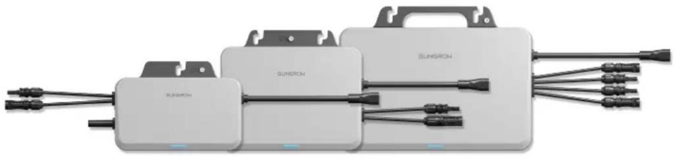
natural_image
Exterior view of a SunRon electric vehicle battery pack with multiple connected cables (no text or symbols visible)EN
- Contents may be periodically updated or revised due to product development. The information in this guide is subject to change without notice. In no case shall this guide substitute for the user manual or related notes on the device.
- Make sure to read over, fully understand and strictly follow the detailed instructions of the user manual and other related regulations before installing the equipment. The user manual can be downloaded by visiting the website at http://support.sungrowpower.com/; or it can be obtained by scanning the QR code on the front of the microinverter or the back cover of this guide.
- All operations can be performed only by qualified personnel, that must be trained for installation and commissioning of electrical system, as well as dealing with hazards, have knowledge of the manual and of the local regulations and directives.
- Before installation, check that the package contents are intact and complete compared to the packing list. Contact SUNGROW or the distributor in case of any damaged or missing components.
- The cable used must be intact and well insulated. Operation personnel must wear proper personal protective equipment (PPE) all the time.
- Any violation could result in personal death or injury or device damage, and will void the warranty.
- Incorporates product approved by Anatel under number 23376-23-11568.
Safety
The inverter has been designed and tested strictly according to international safety regulations. Read all safety instructions carefully prior to any work and observe them at all times when working on or with the inverter. Incorrect operation or work may cause:
- injury or death to the operator or a third party.
• damage to the inverter or other properties.
Please follow the safety instructions related to the PV strings and the utility grid.
Security Declaration
- To learn more about the product network security vulnerability response process and vulnerability disclosure, please scan the QR code below or visit the following website: https://en.sungrowpower.com/security-vulnerability-management
text_image
QR code image containing encoded data, no visible human-readable text
DANGER
Lethal voltage!
- PV strings will produce electrical power when exposed to sunlight and can cause a lethal voltage and an electric shock.
- Only qualified personnel can perform the wiring of the PV panels.
- All electrical connections must be in accordance with local and national standards.
- Only with the permission of the local utility grid company, the inverter can be connected to the utility grid.
- Do not open the enclosure at any time. Unauthorized opening will void warranty and warranty claims and in most cases terminate the operating license.
- When the enclosure lid is removed, live components can be touched which can result in death or serious injury due to electric shock.
Lethal danger from electric shock due to possibly damaged inverter
- Only operate the inverter when it is technically faultless and in a safe state.
- Operating a damaged inverter can lead to hazardous situations that can result in death or serious injuries due to electric shock.

WARNING
Risk of inverter damage or personal injury
- Do not pull out the PV connectors and AC connector when the inverter is running. Disconnect the AC circuit breaker. Wait 10 minutes for the internal capacitors to discharge. Verify that there is no voltage or current before pulling any connector.
- Even after the microinverter has been stopped, it may still be hot and cause burns. Wait 30min until the microinverter cools down, and then perform operations on it wearing protective gloves.

WARNING
All the warning labels and nameplate on the inverter body:
- must be clearly visible.
- must not be removed, covered or pasted.

CAUTION
Risk of burns due to hot components!
- Do not touch any hot parts (such as the heat sink) during operation.

NOTICE
Only qualified personnel can perform the country setting. Unauthorized alteration may cause:
• A breach of the type-certificate marking.
Risk of inverter damage due to electrostatic discharge (ESD)!
By touching the electronic components, you may damage the inverter. For inverter handling, be sure to:
• avoid any unnecessary touching.
- wear a grounding wristband before touching any connectors.
MicroInverter
The warning label on the inverter body are as follows.
Danger to life due to high voltages! Only qualified personnel can open and maintain the inverter.
Disconnect the inverter from all the external power sources before maintenance!

Read the user manual before maintenance!
CE mark of conformity. EU/EEA Importer.

TÜV mark of conformity.
Burn danger due to hot surface that may exceed 60 °C.
Do not touch live parts for 10 minutes after disconnection from the power sources.
Do not dispose of the inverter together with household waste.

RoHS labeling The product complies with the requirements of the applicable EU directives.

UTE C15-712-1 Warning label for installation.
Manufacturer :
Sungrow Power Supply Co., Ltd.
No 1699. Xiyou Road, Hefei 230088. P.R. China
For EU only
EU Declaration of Conformity

within the scope of the EU directives
The object of the declaration described above is in conformity with the relevant Union harmonisation legislation:
The radio Equipment Directive 2014/53/EU (RED)
Low Voltage Directive 2014/35/EU (LVD)
Electromagnetic compatibility 2014/30/EU (EMC)
Restriction of the use of certain hazardous substances 2011/65/EU and 2015/863/EU (RoHS)
The manufacturer Sungrow Power Supply Co., Ltd., China hereby confirms that the product S450S,S800S,S1000S,S1600S complies with the essential requirements and other relevant provisions of Directives 2014/53/EU (RED), 2014/35/EU(LVD) and 2014/30/EU (EMC),2011/65/EU and 2015/863/EU (RoHS).The full EU Declaration of Conformity can be found at https://support.sungrowpower.com/PdfDetail?id=1790188194723446785
The communication module that comes with the inverter and the technical parameters of wireless communication are listed in the table below. The model of the communication module actually delivered shall prevail. The EU Declaration of Conformity for the communication module can be found at support.sungrowpower.com.
Microinverter(WIFI):
Radio technology
WLAN 802.11b/g/n
Radio spectrum
2412 MHz \~ 2472MHz
Maximum transmission power
≤ 20 dBm
Technical parameters listed above apply to EU countries only.
FR
text_image
QR code image containing encoded data, no visible human-readable text
DANGER
Tension mortelle !
Sungrow Power Supply Co., Ltd.
No 1699. Xiyou Road,Hefei 230088.P.R.China
text_image
QR code image containing encoded data, no visible human-readable text
GEFAHR
Sungrow Power Supply Co., Ltd.
Nr. 1699. Xiyou Road, Hefei 230088.P.R.China
Nur für die EU
https://support.sungrowpower.com/PdfDetail?id=1790190511526952961
https://en.sungrowpower.com/security-vulnerability-management

text_image
QR code image containing encoded data, no visible human-readable text
GEVAAR
Sungrow Power Supply Co., Ltd.
No 1699. Xiyou Road, Hefei 230088.P.R.China
Alleen voor de EU
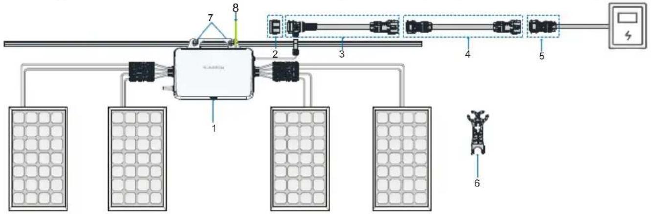
* The images shown here are for reference. The actual product and quantity are based on delivery.
flowchart
graph TD
    A["Power Supply Unit"] --> B["Component 1"]
    A --> C["Component 2"]
    A --> D["Component 3"]
    A --> E["Component 4"]
    A --> F["Component 5"]
    A --> G["Component 6"]
    B --> H["Solar Panel 1"]
    C --> I["Solar Panel 2"]
    D --> J["Solar Panel 3"]
    E --> K["Solar Panel 4"]
    F --> L["Solar Panel 5"]
    G --> M["Solar Panel 6"]
    H --> N["External Control Unit"]
    I --> N
    J --> N
    K --> N
    L --> N
    M --> N
| NO. | Definition | Model | Description |
| Microinverter1 | S450S/S800S/S1000S/S1600S | Included in the scope of delivery as standard equipment. | |
| 2 | Sealing cap for T type connector | MC-EC01 | Users place separate orders. Used to seal off the unused port on the T-type connector. |
| 3 | AC cable with T type connector_25 | MEC-2.8T01 | Users place separate orders.Used to connect two microinverters. |
| 4 | AC extension cable_25 | MEC-2.8AE01 | Optional. Used when the distance between two microinverters exceeds 2.8m. |
| 5 | AC connector_male | MC-M01 | Users place separate orders.Used to connect the microinverter to the power distribution box. |
| 6 | AC connector unlock tool | MIT-DT01 | Users place separate orders. Used to disconnect two T-type AC trunk cables, or disconnect the T-type AC trunk cable from the microinverter. |
| 7 M8 | fixing screw M8 | Prepared by users. Used to fix the microinverter. | |
| 8 | Grounding cable | Recommended cross-section of the cable:2.5 mm2 | Prepared by users.Used for external grounding of Microinverter. |
| Grounding screw | M4 | Included in the scope of delivery.Used for external grounding of Microinverter. |
* Note: Only the power distribution box is allowed to be connected to the AC grid-connected side.
Installation Tool / Werkzeuge zur Installation / Outil d'installation / Montagegereedschap
natural_image
Simple illustration of a sharpened pencil with no text or symbols on the pencil itself
text_image
Crimping tool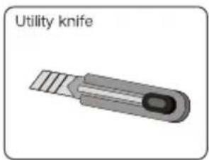
text_image
Utility knife
natural_image
Illustration of a wire cutter with pliers (no text or symbols on the tool itself)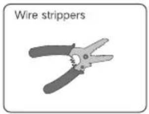
text_image
Wire strippers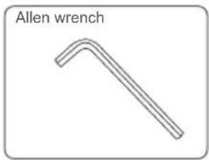
text_image
Allen wrench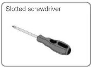
natural_image
Illustration of a slotted screwdriver with no text or symbols on the tool itselfMounting location / Emplacement de montage / Montageort / Montageplaats
The average temperature approximately 20 cm around the microinverter should be taken as its operating temperature. The temperature and humidity should meet the requirements below:

text_image
Warning symbol with exclamation mark inside a triangle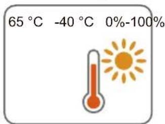
text_image
65 °C -40 °C 0%-100%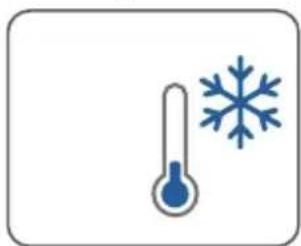
natural_image
Illustration of a thermometer and snowflake (no text or symbols)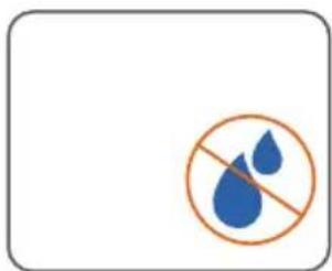
natural_image
Prohibition sign with two blue water droplets inside a circle, no text or symbols presentProduct Appearance&Dimensions / Apparence et dimensions du produit / Erscheinungsbild und Abmessungen des Produkts / Uiterlijk en afmetingen van product
S450S:
text_image
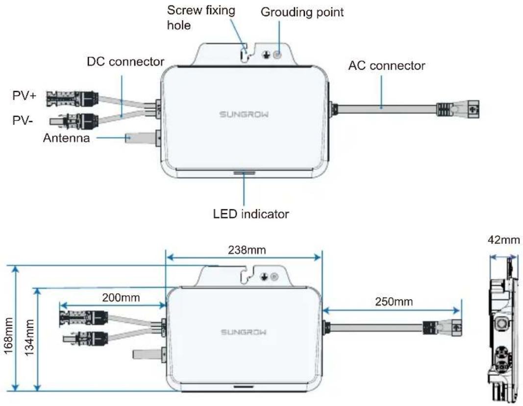
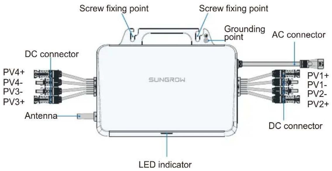
Screw fixing hole Grounding point DC connector AC connector PV+ PV- Antenna SUNGROW LED indicator 238mm 168mm 134mm 200mm 250mm 42mm SUNGROWS800S/S1000S:
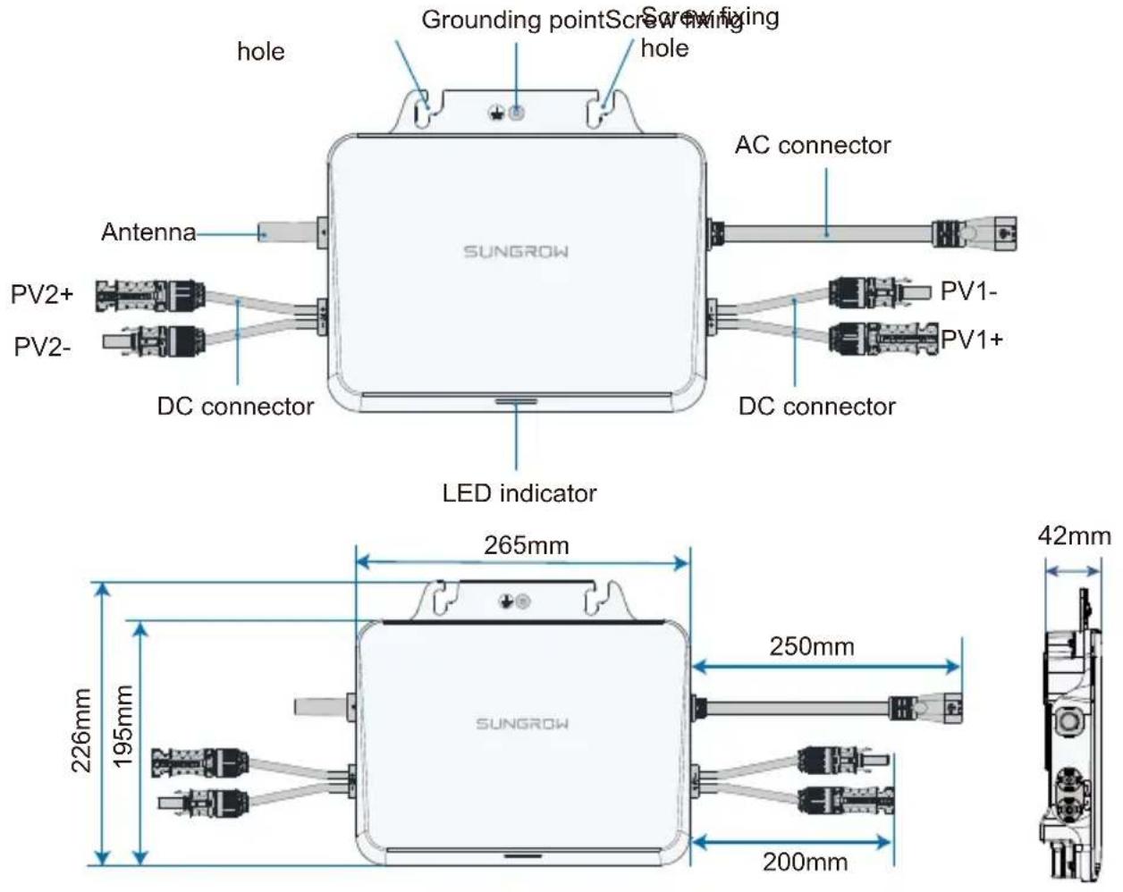
S1600S:
text_image
Screw fixing point Screw fixing point Grounding point AC connector DC connector PV4+ PV4- PV3- PV3+ Antenna SUNGROW LED indicator PV1+ PV1- PV2- PV2+ DC connector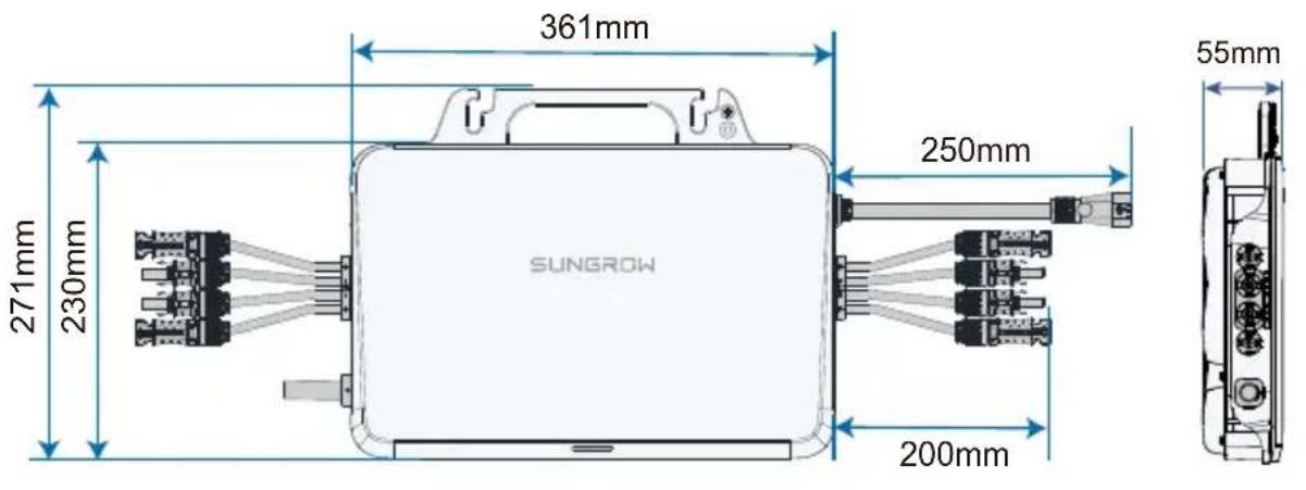
text_image
361mm 271mm 230mm 250mm SUNGROW 200mm 55mm- Do not bump, squeeze, or bend its connectors or Wi-Fi antenna when handling the microinverter. Deformation or damage may impair the device's performance or normal operation.
- Do not lift the cable by hand when handling the device. The S450S, S800S and S1000S microinverters do not have handles. You may move the device by gripping the groove on its back.
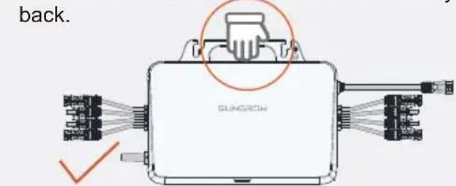
text_image
back. SUNGROW(Recommended)
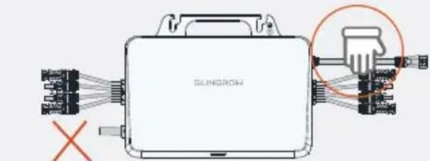
text_image
SUNGROW X(Prohibited)
1
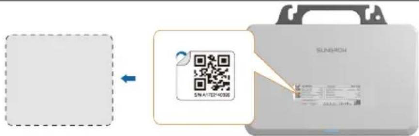
text_image
SINGHOU SN A17214036Remove one of the two identical QR code labels on the device enclosure, and stick it inside the dotted box on the left (if multiple microinverters are used, put their QR codes on the blank page before this Guide's back cover). This QR code is used for iSolarCloud related operations.
- The QR code on the nameplate is not intended for iSolarCloud related operations.
2
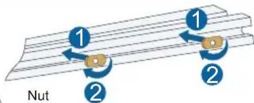
text_image
1 1 2 2 Nut
(not included in the scope of delivery)
3
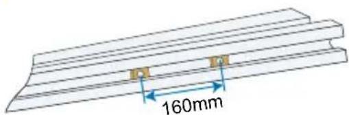
text_image
160mm4
natural_image
Technical diagram of a Sunrow solar panel assembly with cooling fans and wiring (no text or symbols)
M8

9.0N·m
Washers should be added to the M8 screws by the user separately. Washers with an inner diameter of 8.5 mm and a thickness of 2.5 mm are recommended; while the outer diameter of the washer must be greater than 24 mm.
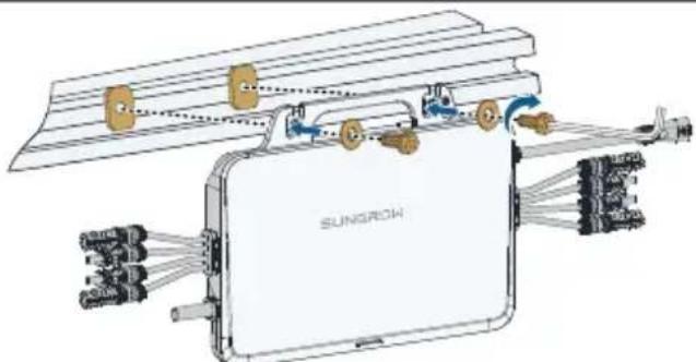
- Avoid placing the device in direct sunlight. It is recommended to install it under the PV module.
- It is recommended that the inverter fixing screws be installed around the roof frame fixing hook.
- Do not mount the microinverter on the edge of the bracket.
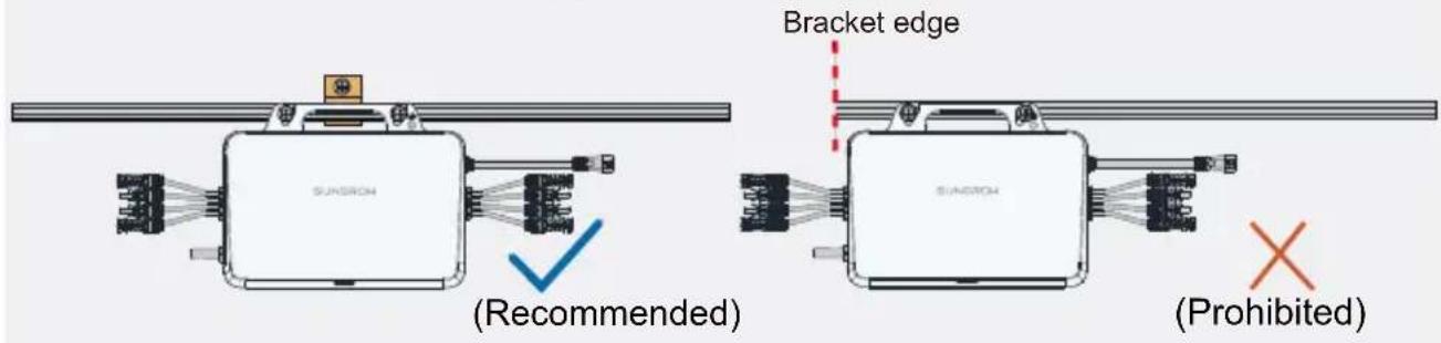
text_image
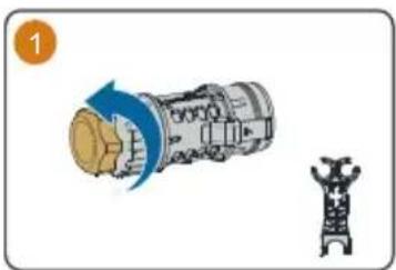
SUNRON Bracket edge (Sunron) (Recommended) SUNRON (Prohibited)Attach AC Male Connector / Fixez le connecteur CA mâle / Bringen Sie den AC-Stecker an / Sluit het mannetje van de AC-connector aan
natural_image
Illustration of a mechanical device with a blue arrow indicating rotation and a separate view of a tower-like structure (no text or symbols)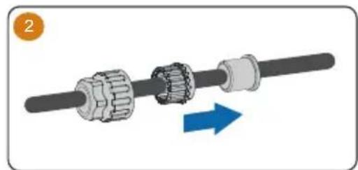
natural_image
Mechanical assembly diagram showing a shaft and gear mechanism with a blue directional arrow (no text or symbols)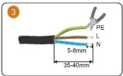
text_image
3 PE L N 5-8mm 35-40mm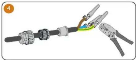
natural_image
Mechanical assembly diagram showing a cable with clamping tools and a highlighted joint (no text or symbols)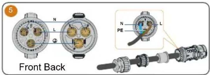
text_image
5 Front Back N L Φ N PE L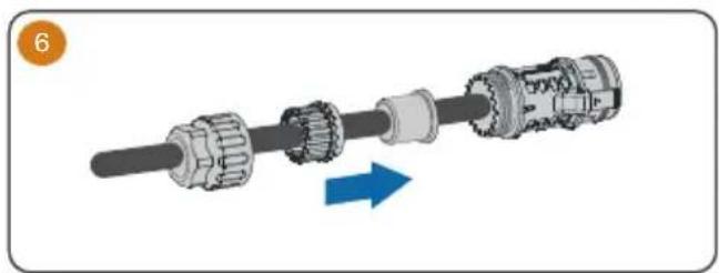
natural_image
Mechanical assembly diagram showing a shaft and gear mechanism with a blue arrow indicating direction (no text or symbols)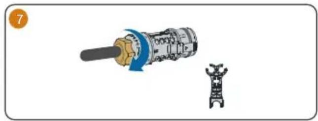
natural_image
Diagram showing a mechanical device with a shaft and a separate 3D model of a robotic arm (no text or symbols)Observe the marks on the terminals when making cables and ensure the polarity is correct. Otherwise, after connecting to the power distribution box, the microinverter may not operate properly, the house's circuit may trip, and it may even result in personal injuries.
Wiring Steps / Procédure de câblage / Verkabelungsschritte / Bedradingsprocedure

Connect the external grounding cable.
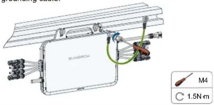
text_image
SUNRICH M4 C 1.5N·mIt is recommended to make a protective ground connection. Lack of protective grounding or unreliable grounding may lead to personal injuries.

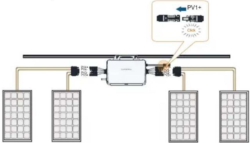
Connect the DC connectors, make sure there is a PV module connected to PV1.
flowchart
graph TD
    A["Power Supply Panel"] --> B["Control Unit"]
    B --> C["Power Supply Panel 1"]
    B --> D["Power Supply Panel 2"]
    B --> E["Power Supply Panel 3"]
    B --> F["Power Supply Panel 4"]
    style A fill:#f9f,stroke:#333
    style B fill:#ccf,stroke:#333
    style C fill:#cfc,stroke:#333
    style D fill:#fcc,stroke:#333
    style E fill:#cff,stroke:#333
    style F fill:#ffc,stroke:#333

WARNING
- The PV1 channel acts as the host and must be connected with PV module. If it is left unconnected, the system may report a fault and cannot operate properly.

CAUTION
- When connecting the DC connectors, make sure the order of the connectors corresponds properly to the actual positions of PV modules at the site, to facilitate the later setup of the physical layout of the plant.
- If not all of the DC connectors on the microinverter are connected to PV modules, use IP67 waterproof plugs to close off the unused connectors. The waterproof plugs should be prepared by the user.
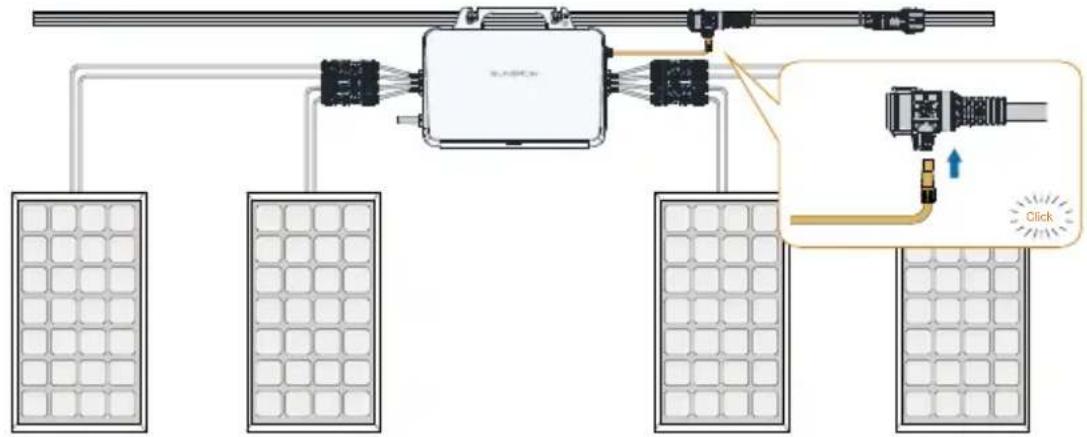
• The total length of the microinverter PV-side DC cable must be<3 m. - If the PV module is located too far away from the microinverter, a DC extension cable is needed. The user needs to make the extension cable first.
- Ensure the PV cables are connected with correct polarity during DC wiring. Otherwise, the microinverter may not operate properly.
• PV modules cannot be connected in series.
3
Connect the AC connector.
text_image
Diagram showing a smart grid connected to an electronic device with labeled components and a zoomed-in view of the device's connection.4
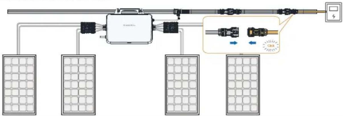
(Optional) Connecting extension cables.
flowchart
graph TD
    A["Central Device"] --> B["Panel 1"]
    A --> C["Panel 2"]
    A --> D["Panel 3"]
    A --> E["Panel 4"]
    B --> F["Panel 5"]
    C --> G["Panel 6"]
    D --> H["Panel 7"]
    E --> I["Panel 8"]
    style A fill:#f9f,stroke:#333
    style B fill:#ccf,stroke:#333
    style C fill:#ccf,stroke:#333
    style D fill:#ccf,stroke:#333
    style E fill:#ccf,stroke:#333
    style F fill:#dfd,stroke:#333
    style G fill:#dfd,stroke:#333
    style H fill:#dfd,stroke:#333
    style I fill:#dfd,stroke:#333
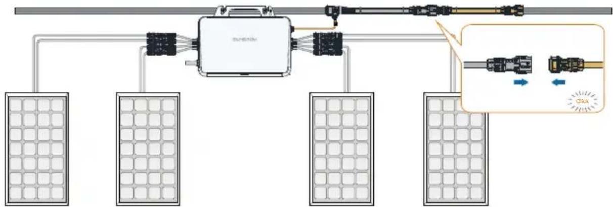
5
Connect the AC male connector.
flowchart
graph TD
    A["Solar Panel"] --> B["Central Device"]
    C["Solar Panel"] --> B
    D["Solar Panel"] --> B
    B --> E["Switch"]
    B --> F["Load"]
    B --> G["Control Unit"]
    H["Zoom"] --> I["Close-up Cable Link"]
    J["Arrow"] --> K["Arrow"]
    L["Arrow"] --> M["Arrow"]
    N["Arrow"] --> O["Arrow"]
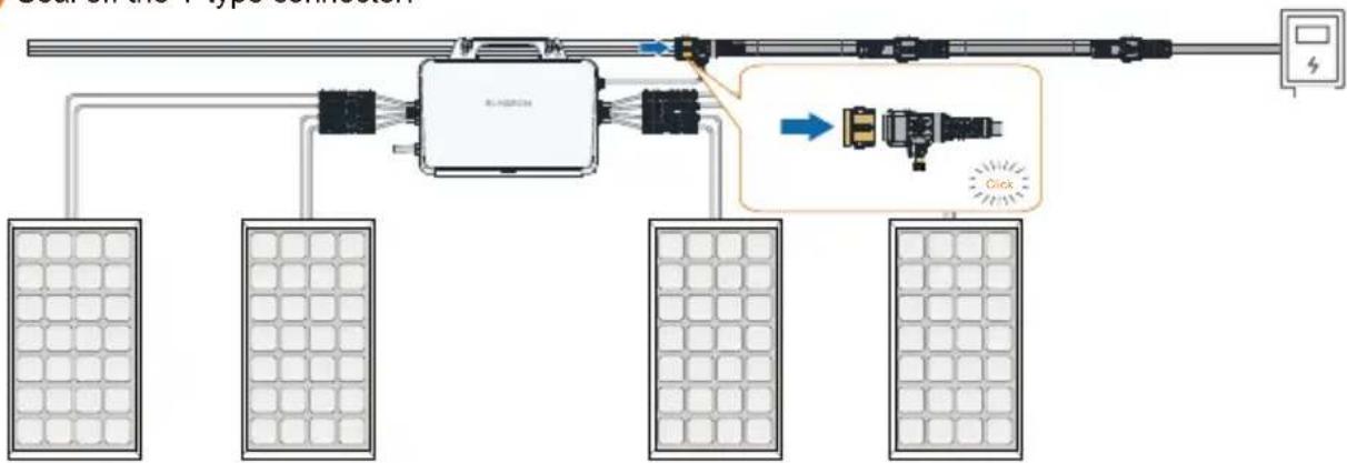
4
Seal off the T-type connector.
flowchart
graph TD
    A["Power Supply Panel"] --> B["Solar Panels"]
    B --> C["Control Panel"]
    C --> D["Motor"]
    D --> E["Display Panel"]
    C --> F["Click Button"]
    style C fill:#f9f,stroke:#333
    style D fill:#ccf,stroke:#333
    style E fill:#cfc,stroke:#333
- Mounted on a Wall
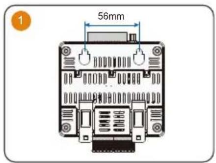
text_image
1 56mm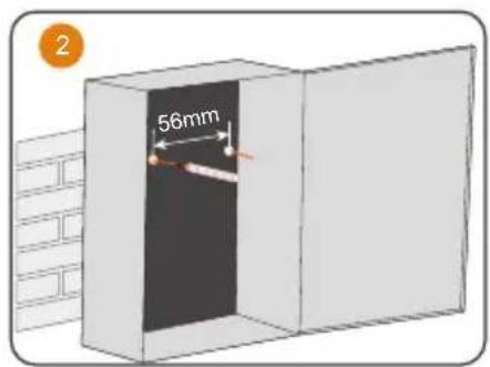
text_image
2 56mm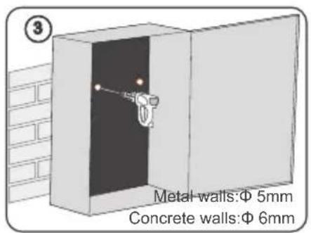
text_image
Metal walls:Φ 5mm Concrete walls:Φ 6mm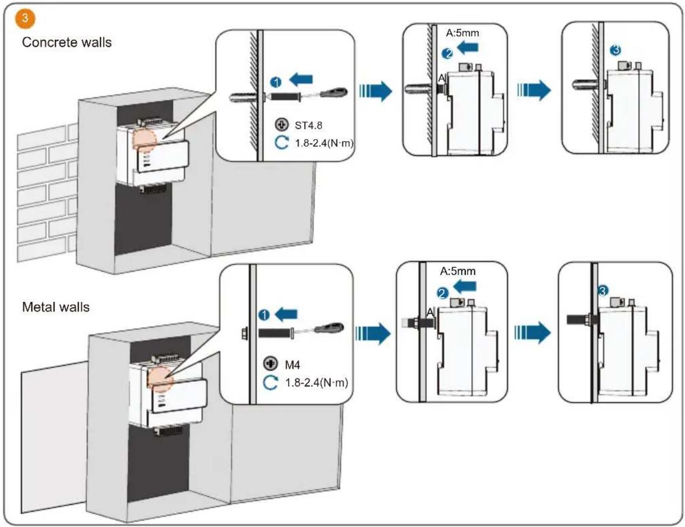
flowchart
graph TD
    A["Concrete walls"] --> B["1: ST4.8 1.8-2.4(N·m)"]
    B --> C["A:5mm"]
    C --> D["2"]
    D --> E["3"]
    E --> F["Metal walls"]
    F --> G["M4 1.8-2.4(N·m)"]
    G --> H["A:5mm"]
    H --> I["2"]
    I --> J["3"]
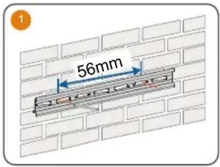
- Mounted on a Guide Rail
text_image
1 56mm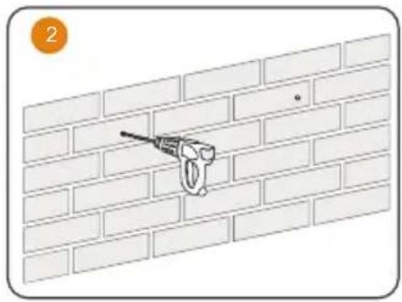
natural_image
Diagram of a brick wall with a tool inserted into it, no text or symbols present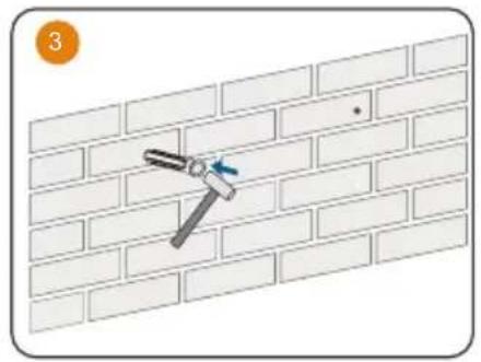
natural_image
Diagram of a hammer fastening a brick wall, showing alignment and angle (no text or symbols)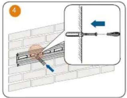
text_image
4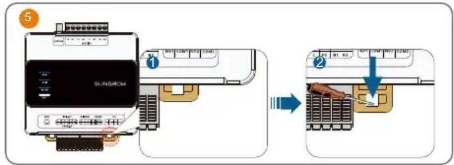
text_image
5 1 SUNSCROM 2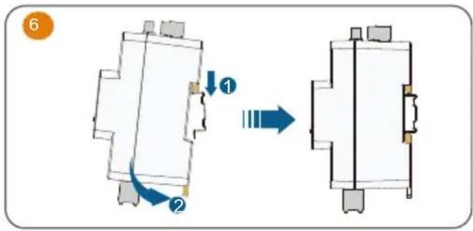
text_image
Diagram showing a mechanical or electrical component transformation with labeled parts and directional arrows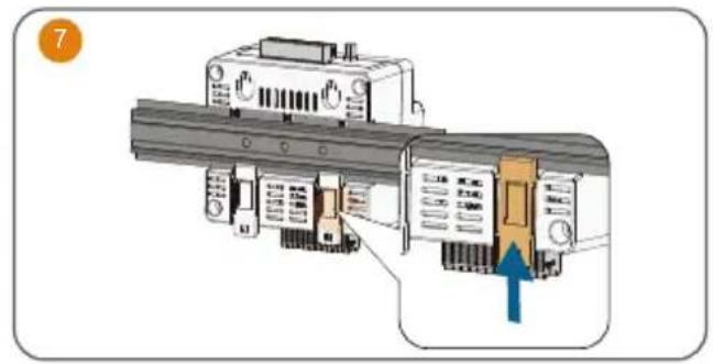
natural_image
Diagram of a mechanical assembly with a highlighted component and directional arrow (no text or symbols)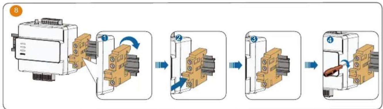
flowchart
graph LR
    A["Motor with attached components"] --> B["Step 1: Rotation of switch"]
    B --> C["Step 2: Rotation of switch"]
    C --> D["Step 3: Rotation of switch"]
    D --> E["Step 4: Rotation of switch"]
- Antenna Installation
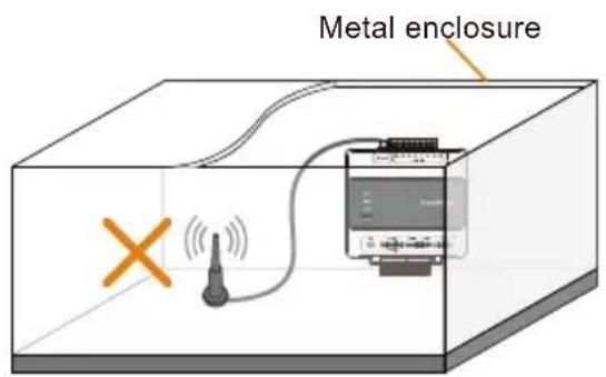
text_image
Metal enclosure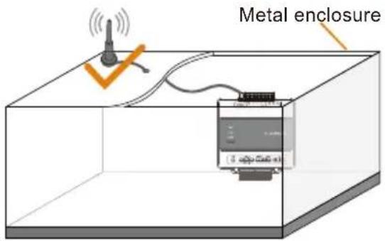
text_image
Metal enclosure- AC and GRID. CT connection
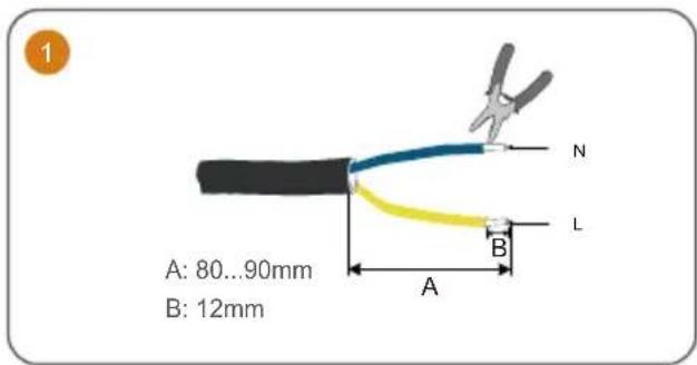
text_image
A: 80...90mm B: 12mm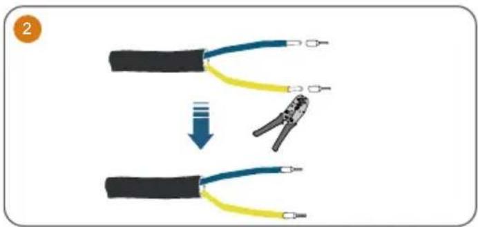
text_image
Diagram showing wire connection steps: first to split cable with yellow and blue wires, second to wire being crimped.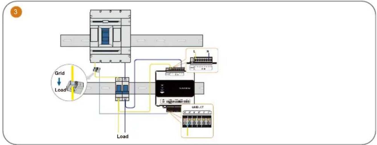
text_image
3 Grid Load Load L N GRID.CTThe iHomeManager comes with three CTs. Connect only one CT to the microinverter.
Commissioning / Mise en service / Inbetriebnahme / Inbedrijfstelling
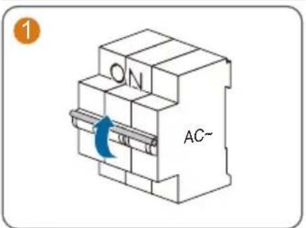
text_image
ON AC~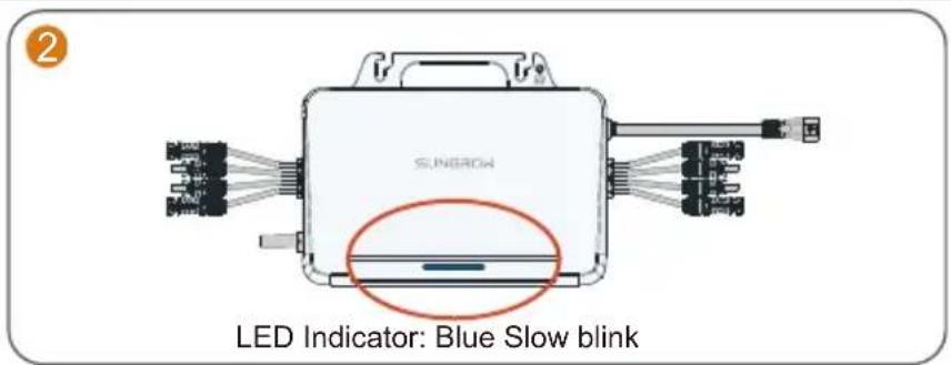
text_image
2 SUNROW LED Indicator: Blue Slow blink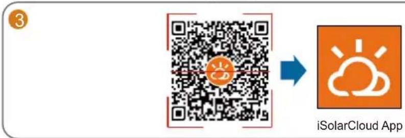
text_image
3 iSolarCloud App- To fully utilize the features of the iSolarCloud App, please grant it access to your camera, location, and network when you first open the App.
- Connect only one mobile phone to the microinverter's hotspot at a time. Otherwise, it may lead to a conflict issue.
- It is suggested to turn off auto network switching on the mobile phone so that it can stay connected to the microinverter's hotspot. Otherwise, the phone may switch to a stronger Wi-Fi signal automatically and its connection to the microinverter will be interrupted. Detailed instructions are provided below, using a Samsung mobile phone as an example:
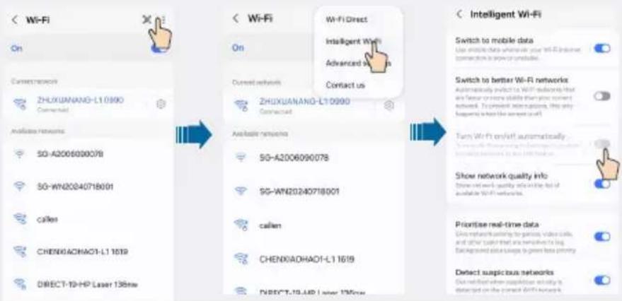
text_image
< Wi-Fi On Current network ZHUXUANANG-L10990 Connected Available networks 5G-A2006000078 5G-WN20240718001 callen CHENGACHAO1-L1 1619 DIRECT-10-HP Laser 136nm < Wi-Fi On Current networks ZHUXUANANG-L10990 Connected Available networks 5G-A2006090078 5G-WN20240718001 callen CHENGACHAO1-L1 1619 DIRECT-10-HP Laser 136nm < Wi-Fi Direct Intelligent Wi-Fi Advanced us Contact us < Intelligent Wi-Fi Switch to mobile data Use mobile data where your Wi-Fi internet connection is open or unavailable. Switch to better Wi-Fi networks Automatically switch to Wi-Fi networks that are fewer or more skills than those current networks. To prevent interruptions, this only happening to have the same user (self) Turn Wi-Fi on/off automatically Show network quality info Show network quality info on the list of available Wi-Fi networks. Priorise real-time data Drive network setting for patients, video calls, and other users that are sensitive to log background data usage to generate privacy Detect suspicious networks Do not mention when supplementation activity is detected on the next Wi-Fi network.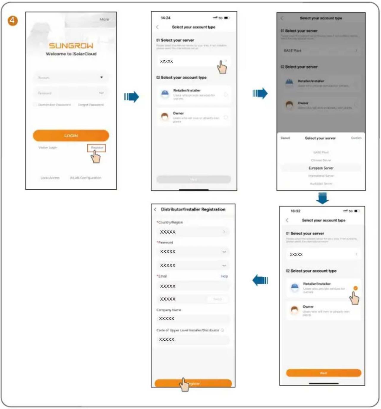
flowchart
graph TD
    A["More"] --> B["14:24"]
    B --> C["Select your account type"]
    C --> D["01 Select your server"]
    D --> E["XXXXXX"]
    E --> F["02 Select your account type"]
    F --> G["Retailer/Installer"]
    G --> H["Owner"]
    H --> I["User who will enter or already open plants"]
    I --> J["Select your account type"]
    J --> K["BASE Plant"]
    K --> L["02 Select your server"]
    L --> M["Retailer/installer"]
    M --> N["Owner"]
    N --> O["Owner"]
    O --> P["Select your server"]
    P --> Q["BASE Plant"]
    Q --> R["Chinese Server"]
    R --> S["European Server"]
    S --> T["International Server"]
    T --> U["Aud3333 Server"]

    V["Login"] --> W["Register"]
    X["Local Access"] --> Y["WLAN Configuration"]

    Z["Distributor/Installer Registration"] --> AA["*Country/Region"]
    AA --> AB["XXXXXX"]
    AB --> AC["*Password"]
    AC --> AD["XXXXXX"]
    AD --> AE["XXXXXX"]
    AE --> AF["*Email"]
    AF --> AG["Help"]
    AG --> AH["XXXXXX"]
    AH --> AI["XXXXXX"]
    AI --> AJ["Company Name"]
    AJ --> AK["XXXXXX"]
    AK --> AL["Code of Upper Level Installer/Distributor"]
    AL --> AM["XXXXXX"]

    AN["Register"] --> AO["Select your account type"]
    AO --> AP["01 Select your server"]
    AP --> AQ["XXXXXX"]
    AQ --> AR["*Password"]
    AR --> AS["XXXXXX"]
    AS --> AT["XXXXXX"]
    AT --> AU["*Email"]
    AU --> AV["Help"]
    AV --> AW["XXXXXX"]
    AW --> AX["XXXXXX"]
    AX --> AY["Company Name"]
    AY --> AZ["XXXXXX"]
    AZ --> BA["Code of Upper Level Installer/Distributor"]
    BA --> BB["XXXXXX"]

    AC --> BC["Select your account type"]
    BC --> BD["01 Select your server"]
    BD --> BE["XXXXXX"]
    BE --> BF["*Password"]
    BF --> BG["XXXXXX"]
    BG --> BH["XXXXXX"]
    BH --> BI["*Email"]
    BI --> BJ["Help"]
    BJ --> BK["XXXXXX"]
    BK --> BL["XXXXXX"]
    BL --> BM["Company Name"]
    BM --> BN["XXXXXX"]
    BN --> BO["Code of Upper Level Installer/Distributor"]
    BO --> BP["XXXXXX"]

    AC --> B
5
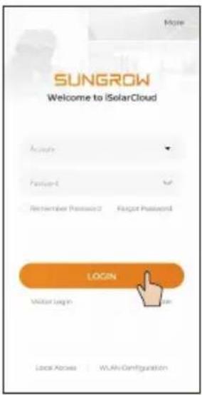
text_image
SUNGROW Welcome to iSolarCloud Login Mitar Login Local Active | WLAV Configuration

text_image
Privacy Policy iSolarCloud Sungrow Deutschland GmbH (also referred to as "Sungrow", "yes", "not" or "not") attaches great importance to your privacy. Therefore, we have worked out a privacy policy that covers how we process your personal data as the data controller when you use our SolarCloud service via the website www.solarcloud.com (the "website") or via the SolarCloud App (the "App"), the website and the App together referred to as "SolarCloud". This privacy policy also tells you how you can exercise your data subject's rights (including the right to object to some of the data handling we carry out). More information about your rights and how you can exercise them is set out in the "Your Rights and Choices" section below. In addition to this privacy policy, we have embedded data and privacy information in DISAGREE AGREE
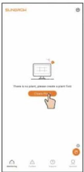
text_image
SUNACH There is no plant, please create a plant fact Create Pin
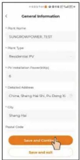
text_image
General Information * Plant Name SUNGROWPOWER_TEST * Plant Type Residential PV * PV Installation Power(kWp) 6 * Detailed Address China, Shang Hai Shi, Pu Dong Xi * City Shang Hai Postal Code Save and Continue Save and exit
text_image
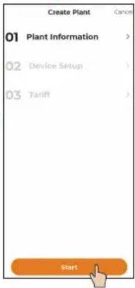
Create Plant Cancel 01 Plant Information > 02 Device Setup > 03 Tariff > StartParameter Description
| *Plant Name | Enter the plant name. |
| *Plant Type | Select the plant type. |
| *PV Installation Power (kWp) | Enter the installed power. |
| *Detailed Address | The location of the plant. |
| *City | The city where the plant is located. |
| Postal Code | The postal code of the place where the plant is located. |
| *Country/Region | The country (region) where the plant is located. |
| *Time Zone | The time zone of the place where the plant is located. |
| Module Model | The model of the PV module actually used in the plant. |
| *Owner's Email Address | Enter the owner's email address. |
| *Grid-connection Type | Set the grid-connection type for the plant. |
| Grid-connected Date | Shows the current date by default. |
| Plant Image | Upload an image of the plant. |
6
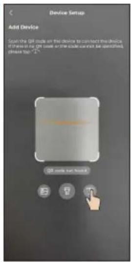
text_image
Device Setup Add Device Scan the QR mode on this device to connect the devices. If these are in the CN mode or the code cannot be identified, please top "1"~ QR mode not found|||
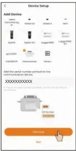
text_image
Device Setup Add Device 100mm (Incrementing) CY 100mm x2 Vitrel 5 VSP1 Eyesys Eyesys x2 Lagger1000 Lipper1000 Ets EMERCEP Heterometer Others Add the serial number printed on the communication devices. XXXXXXXXXXXX S/N S/N Number ADAMXXX Cotinine East→
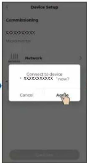
text_image
Device Setup Commissioning XXXXXXXXX: MacIntverter Network Connect to device *XXXXXXXXX *now? Cancel Agile→
text_image
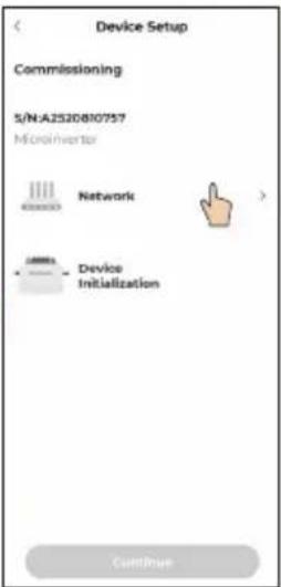
Device Setup Commissioning S/N:A2520810757 Microinverter Network Device Initialization Continue7
text_image
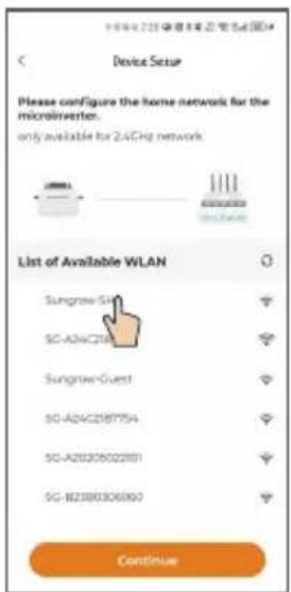
Device Setup Please configure the home network for the microinverter. only available for 2.4GHz network List of Available WLAN Sungrow-SH SC-ADAC218 Sungrow-Guest SC-ADAC2187754 SC-A20205022801 SC-BZ390306060 Continue11
text_image
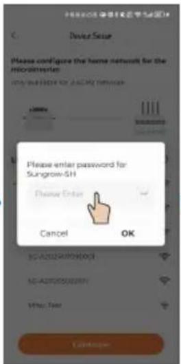
Device Seal Please configure the home network for the microcomputer check your connection for SAGS2016 Please enter password for Sungrow-SH Please Enter Cancel OK SC-A20250000003 SC-A20250000004 http://doi Cancapaper→
text_image
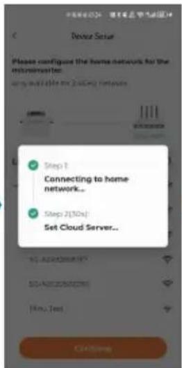
Step 1 Connecting to home network... Step 2(30s) Set Cloud Server...||→
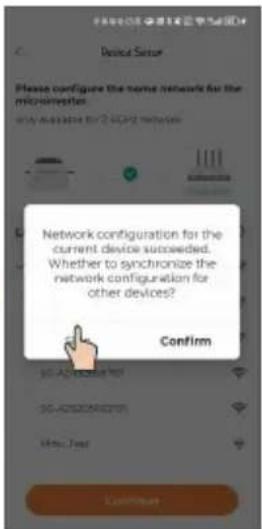
text_image
Device Setup Please configure the home network for the microphones. www.nuobao.com/2.10432 networks Network configuration for the current device succeeded. Whether to synchronize the network configuration for other devices? Confirm http://www.nuobao.com/ http://www.nuobao.com/ http://www.nuobao.com/ Confirm- If there is one microinverter only, you can choose "SKIP". The network configuration is then completed.
- If there are multiple microinverters, you can choose "CONTINUE" to complete the network configuration for other microinverters. For details, see Step 8.Microinverters for which network settings are synchronized in this step will be added to the plant's device list simultaneously.
8
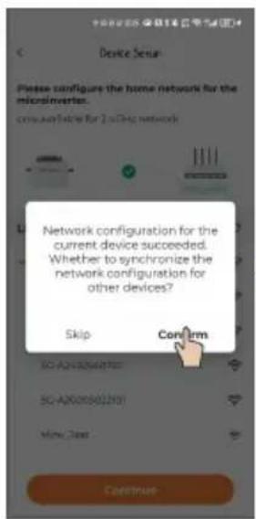
text_image
Device Setup Please configure the home network for the microinverters. com available for 2.0% network Network configuration for the current device succeeded. Whether to synchronize the network configuration for other devices? Skip Confirm SO-A2000000701 SO-A2000000201 Mini Class Continue→
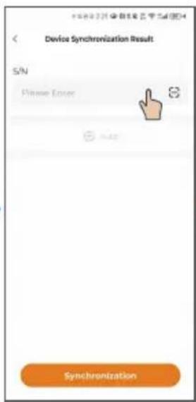
text_image
Device Synchronization Result S/N Please Error S S Synchronization→
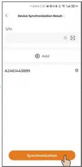
text_image
Device Synchronization Result : S/N Add A2461443899 Synchronization→
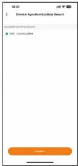
text_image
10:31 Device Synchronization Result Successful Sync/Transitions SIN: A244443995 Outflow9
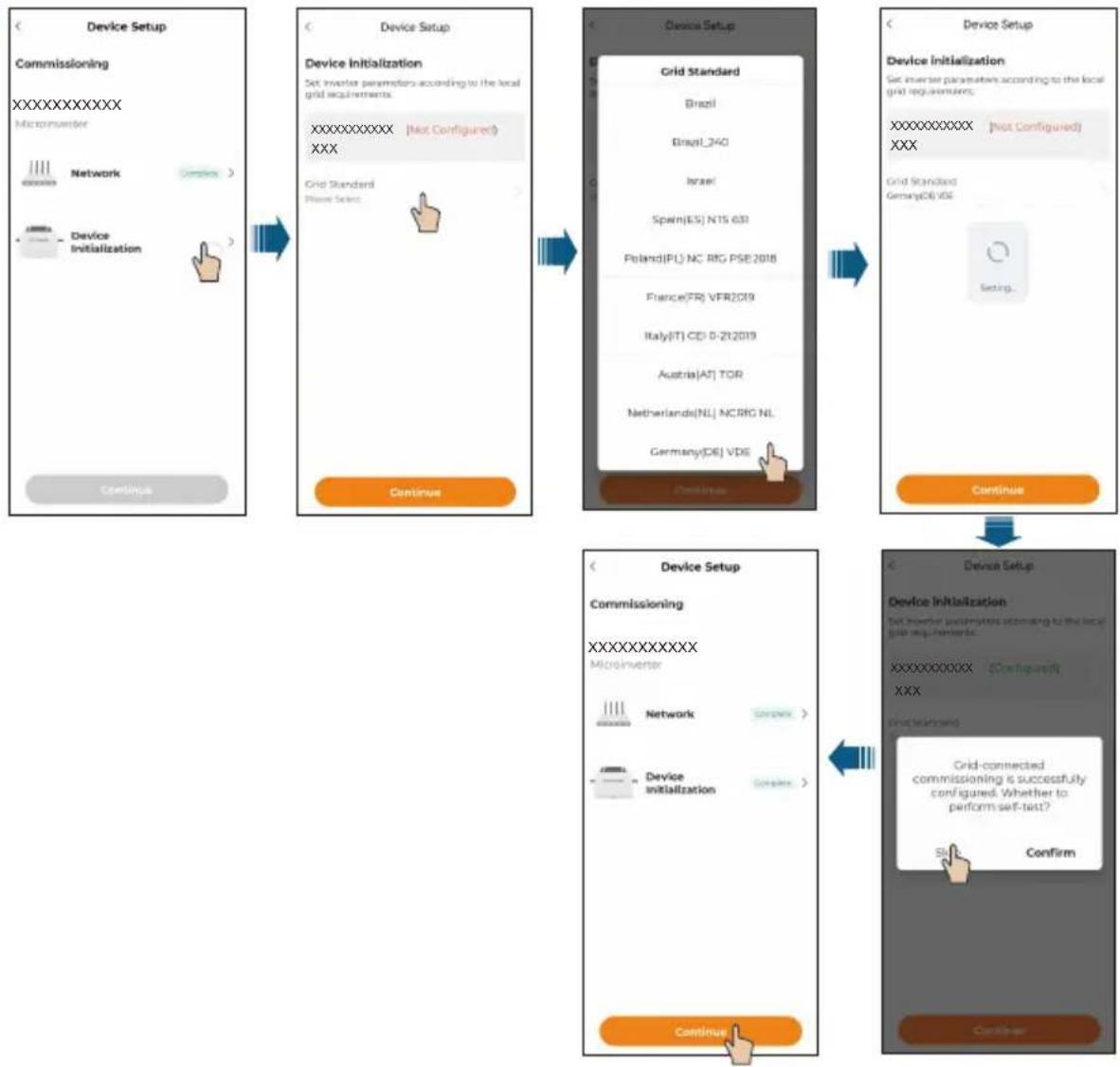
flowchart
graph TD
    A["Device Setup"] --> B["Commissioning"]
    B --> C["MicroInverter"]
    C --> D["Network"]
    D --> E["Device Initialization"]
    E --> F["Continue"]

    G["Device Setup"] --> H["Grid Standard"]
    H --> I["Brazil"]
    H --> J["Brazil_340"]
    H --> K["Israel"]
    H --> L["Spain(ES) N15 639"]
    H --> M["Poland(PL) NC RIG PSE2018"]
    H --> N["France(FR) VFR2019"]
    H --> O["Italy(IT) CD 0-212019"]
    H --> P["Austria(AT) TOR"]
    H --> Q["Netherlands(NL) NCRIG NL"]
    H --> R["Germany(DE) VDE"]
    H --> S["Continue"]

    T["Device Setup"] --> U["Device Initialization"]
    U --> V["Set Inverter parameters according to the local grid requirements."]
    V --> W["XXXXXXXXX (Configuration)"]
    W --> X["Start test setup"]
    X --> Y["Grid-connected commissioning is successfully configured. Whether to perform self-test?"]
    Y --> Z["Start"]
    Z --> AA["Confirm"]
    AA --> AB["Continue"]
10 Optional
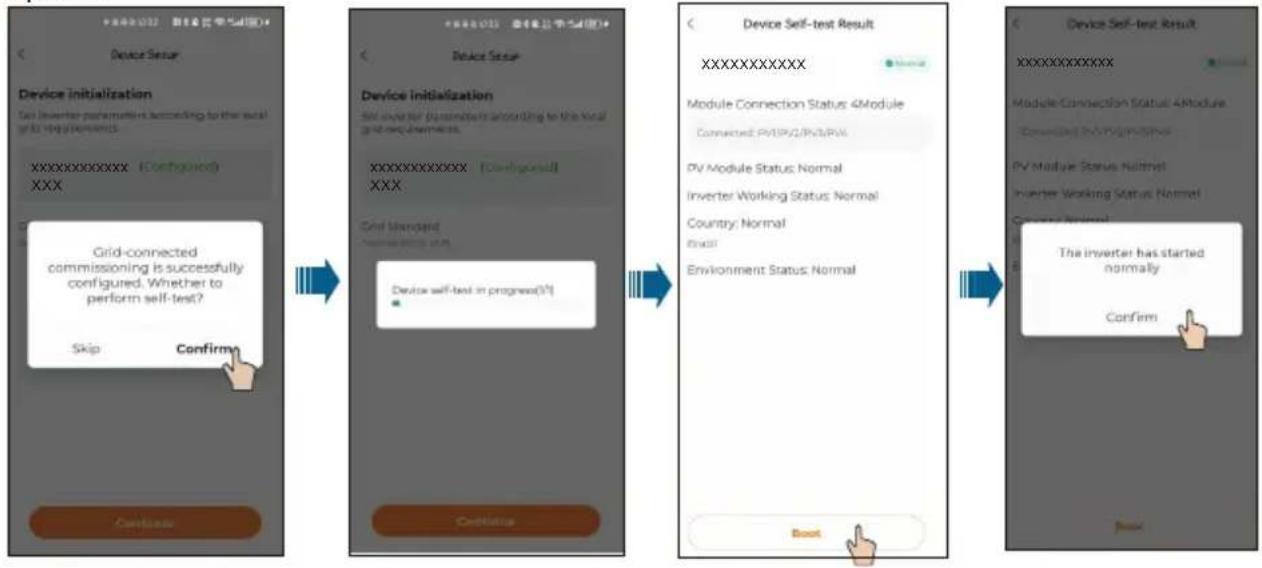
flowchart
graph LR
    A["Device Setup"] --> B["Device Initialization"]
    B --> C["Device Self-Test Result"]
    C --> D["Configuration"]
    D --> E["Confirm"]
- When you change the router, please set up the network connection again. The steps are: log in to the iSolarCloud App, tap the WLAN Configuration, and select the home network to connect to it.
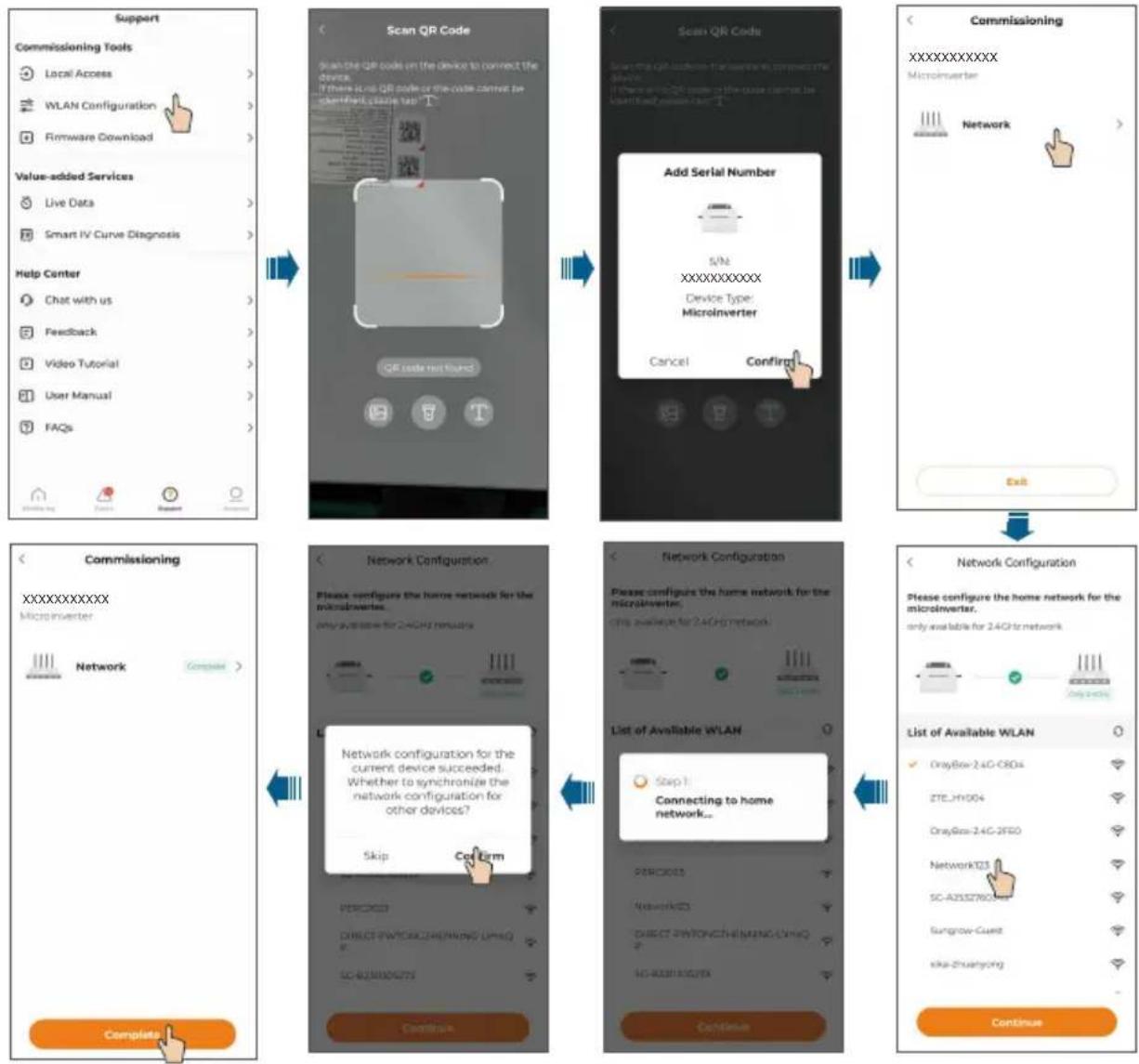
flowchart
graph TD
    A["Support"] --> B["Commissioning Tools"]
    B --> C["Local Access"]
    B --> D["WLAN Configuration"]
    B --> E["Firmware Download"]
    A --> F["Value-added Services"]
    F --> G["Live Data"]
    F --> H["Smart IV Curve Diagnosis"]
    A --> I["Help Center"]
    I --> J["Chat with us"]
    I --> K["Feedback"]
    I --> L["Video Tutorial"]
    I --> M["User Manual"]
    I --> N["FAQs"]

    A --> O["Commissioning"]
    O --> P["Complementary"]

    P --> Q["Network Configuration"]
    Q --> R["Please configure the home network for the microinverter. only available for 2.4GHz remote"]

    Q --> S["Network Configuration"]
    S --> T["Please configure the home network for the microinverter. this available for 2.4GHz network"]

    S --> U["List of Available WLAN"]
    U --> V["Step 1 Connecting to home network..."]

    V --> W["Continue"]

    A --> X["Scan QR Code"]
    X --> Y["Scan QR code on the device to connect the device. If there is QR code or the code cannot be standardization too high"]

    X --> Z["QR code not found"]

    X --> AA["Add Serial Number"]
    AA --> AB["S/N XXXXXXXXXXX Device Type: Microinverter"]
    AA --> AC["Cancel Confiring"]

    X --> AD["Commissioning"]
    AD --> AE["XXXXXXXXXXXX Microinverter"]
    AD --> AF["Network"]

    O --> AG["Network Configuration"]
    AG --> AH["Please configure the home network for the microinverter. only available for 2.4GHz remote"]

    AG --> AI["List of Available WLAN"]
    AI --> AJ["GrayBox-2.4G-CRDs"]
    AI --> AK["ZTE_H1004"]
    AI --> AL["GrayBox-2.4G-3FEO"]
    AI --> AM["Network123"]
    AI --> AN["SC-A2552N60A"]
    AI --> AO["Sungrow-Cuest"]
    AI --> AP["ska-Zhuangong"]

    O --> AQ["Complete"]
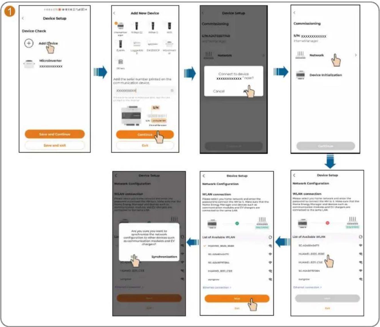
If an iHomeManager is installed, choose "Add Device" at the end of Step 9 to add and configure the iHomeManager. Detailed instructions are provided below.
flowchart
WLAN device setup flowchart covering device setup, add new device, device setup with commissioning and network configuration, and connection to existing LAN.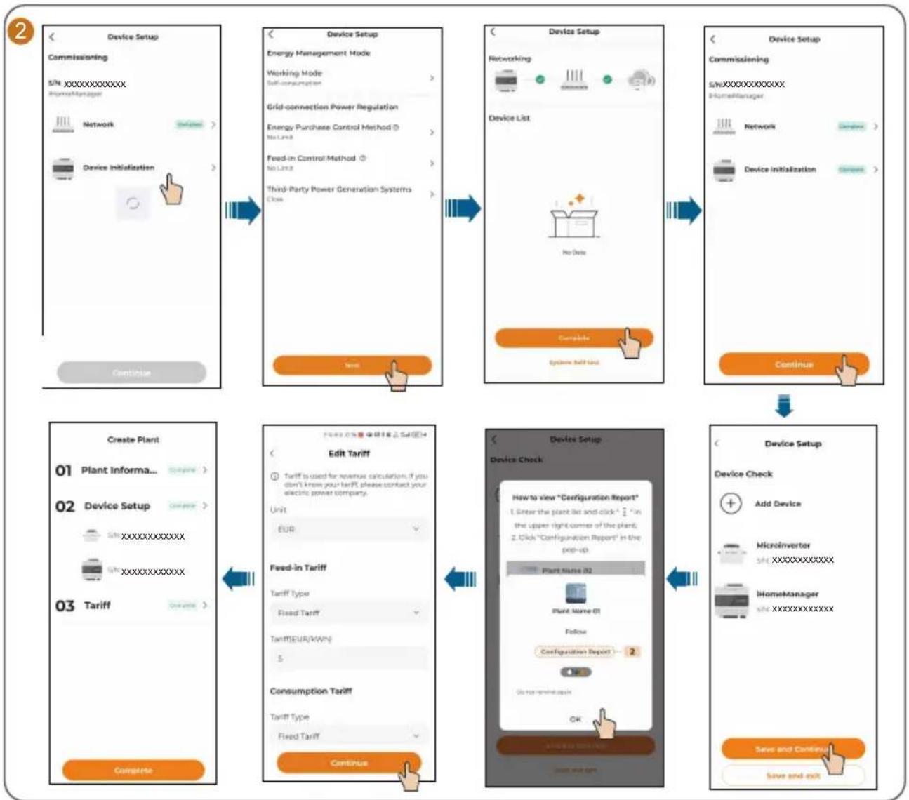
flowchart
graph TD
    A["Device Setup Commissioning\nS/N_XXXXXXXXXX HomeManager\nNetwork\nDevice Initialization"] --> B["Device Setup Energy Management Mode\nWorking Mode\nSelf-consumption"]
    B --> C["Device Setup Networking\nDevice List\nNo Data\nComplete\nSystems Self Unit"]
    C --> D["Device Setup Commissioning\nS/NXXXXXXXXXX HomeManager\nNetwork\nDevice Initialization"]
    D --> E["Create Plant\n01 Plant Informa..."]
    E --> F["Edit Tariff\nTariff is used for revenue calculation if you don't know your tariff, please contact your electric power company\nUnit: EUR"]
    F --> G["Feed-in Tariff\nTariff Type: Fixed Tariff\nTariff/EUR/MWV: $"]
    G --> H["Consumption Tariff\nTariff Type: Fixed Tariff"]
    H --> I["Continue"]
    I --> J["Device Setup Device Check\nHow to view "Configuration Report"\n1. Show the plant list and click * 2 in the upper right corner of the plant;\n2. Click "Configuration Report" in the pop-up\nPlant Name 02\nPlant Name 01\nFollow\Configuration Report -- 2\nOK\nSave and Continue\nSave and exit"]
    J --> K["Device Setup Device Check\nAdd Device\nMicroinverter\nS/N_XXXXXXXXXX\nIHomeManager\nS/N_XXXXXXXXXX"]
The plant that has been created will be shown on the "Monitoring" screen. You can tap a plant to check the detailed information about the plant and its devices, as shown in the figure below.
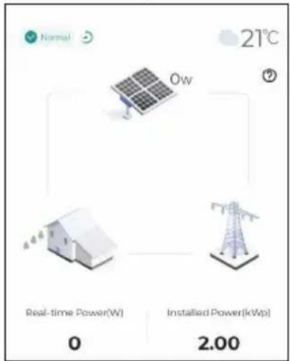
text_image
Normal 21°C Ow Real-time Power(W) 0 Installed Power[kWp] 2.00At night, since there is no light, the microinverter in the plant stops working due to the absence of power source. In this case, it does not communicate with the background and its status shows "offline". However, this does not indicate a fault in the device. Once the light conditions return to normal, with stable power source, the microinverter will start up and work again. It will then communicate with the background normally and its status will be "online". If the device stays offline for a long time or in case of other abnormal symptoms, inspect the device and its network connection.
Check Microinverter Status
Choose the "Device" tab on the top of the screen to check the devices in the plant and their status.
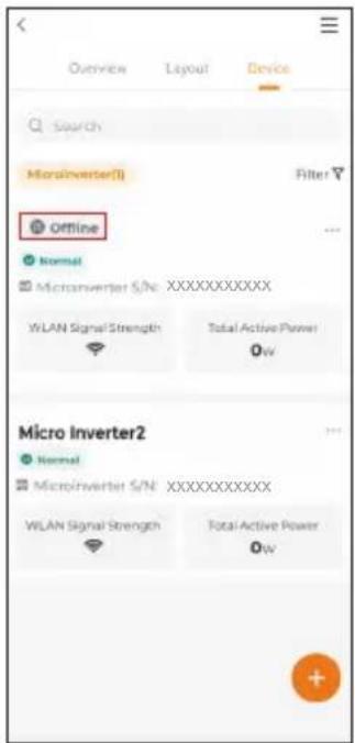
text_image
Overview Layout Device Search MicroInverter(I) Filter Offline Normal Microinverter S/N:XXXXXXXXXX WLAN Signal Strength Total Active Power 0w Micro Inverter2 Normal Microinverter S/N:XXXXXXXXXX WLAN Signal Strength Total Active Power 0wIf a microinverter in the list remains offline for an extended period (excluding the situation that the microinverter goes offline at night, which is normal), follow the troubleshooting steps below.
- Check that the home router network is functioning properly.
- Check that the microinverter is using the correct password to connect to the network.
- Determine if the signal is weak because the microinverter is too far from the router. If necessary, add a Wi-Fi extender between the microinverter and the router.
LED Indicator / Voyant DEL / LED-Anzeige / Led-indicator
| Status indicator Color Status | Description | ||
| Blue | Steady on | Running in on-grid state | |
| Blink slow | Standby or starting up | ||
| Red | Steady on | Fault (inverter failure, update failed, etc.) | |
| Blink slow | Updating | ||
| Grey Off | Powered off | ||
If multiple microinverters are used, paste their QR code labels below.

natural_image
Grid of 16 empty gray rectangular boxes with dashed outlines, no text or symbols present
text_image
QR code with a central orange circular logo containing a document or folder iconFor more product information, visit
http://support.sungrowpower.com/ or scan the QR code