K204 - Thermometer VOLTCRAFT - Free user manual and instructions
Find the device manual for free K204 VOLTCRAFT in PDF.
| Product type | 4-channel digital type K thermometer |
| Model | K204 |
| Brand | VOLTCRAFT |
| Measurement range (K probe) | -200°C to +1370°C / -328°F to +2498°F |
| Range with supplied probes | -50°C to +200°C / -58°F to +392°F |
| Resolution | 0.1°C (up to 199.9°C), 1°C beyond |
| Accuracy (instrument) | ±(0.2% + 1.0 K) for 0°C to 199.9°C ; ±(0.5% + 1.0 K) for -200°C to 0°C and 200°C to 399°C |
| Display | 4-digit LCD x 4, with symbols and units |
| Input channels | 4 inputs (T1, T2, T3, T4) for type K probes |
| Special functions | MAX/MIN, HOLD, REL (relative measurement), T1-T2 (difference), °C/°F switching, backlight |
| Interface | RS-232 via 3.5 mm stereo jack (bidirectional) |
| Auto power off | Yes, after 30 minutes (can be disabled by holding HOLD while switching on) |
| Power supply | 9V block battery (NEDA 1604 or 6F22) or 9V DC mains adapter, 100 mA min, connector Ø3.5/1.35 mm, negative pole inside |
| Dimensions (L × W × H) | 184 × 64 × 30 mm (without cables) |
| Weight | 210 g (with battery) |
| Operating temperature | 0°C to +50°C |
| Storage temperature | -10°C to +60°C |
| Safety | Complies with DIN VDE 0411, EN 61010-1 ; do not use under voltage or in explosive atmosphere |
| Cleaning | Dry antistatic cloth; do not use solvents |
| Calibration | Recommended once a year |
| Included accessories | 2 type K probes TP-K01 (-50°C to +200°C), instruction manual |
Frequently Asked Questions - K204 VOLTCRAFT
User questions about K204 VOLTCRAFT
0 question about this device. Answer the ones you know or ask your own.
Ask a new question about this device
Download the instructions for your Thermometer in PDF format for free! Find your manual K204 - VOLTCRAFT and take your electronic device back in hand. On this page are published all the documents necessary for the use of your device. K204 by VOLTCRAFT.
USER MANUAL K204 VOLTCRAFT
© Copyright 2008 by Voltcraft®
GB Impressum /legal notice in our operating instructions
These operating instructions are a publication by Voltcraft®, Lindenweg 15, D-92242 Hirschau/Germany, Phone +49 180/586 582 7 (www.voltcraft.de).
All rights including translation reserved. Reproduction by any method, e.g. photocopy, microfilming, or the capture in electronic data processing systems require the prior written approval by the editor. Reprinting, also in part, is prohibited.
These operating instructions represent the technical status at the time of printing. Changes in technology and equipment reserved.
© Copyright 2008 by Voltcraft®
© Copyright 2008 by Voltcraft®
© Copyright 2008 by Voltcraft®
01_1108_02/HK
GB This operating manual belongs to this product. It contains important information on the commissioning and handling of the product. Please bear this in mind, even if you pass it on to other people.
Please keep this operating manual for future reference!
A list of the contents can be found on page 23 in the table of contents, indicating the number of the relevant pages.
"P -0FF --- 3.....2.....1"
With the Digital Thermometer 304 you have purchased a state-of-the-art temperature measuring device.
The design corresponds to DIN VDE 0411, Part 1 for measuring devices = EN 61010-1. Moreover it is EMC-tested (for the interior domain) thus fulfilling the requirements of the established European and national guidelines. The conformity has been proven and the relevant documents are in the possession of the manufacturer.
To preserve this condition and to ensure safe operation, the user has to observe this operating manual!
In case of technical questions please contact us:
Germany: Tel. 0180/5 31 21 11,
Fax 0180/5 31 21 10
E-mail: Please use our contact form in the Internet:
www.conrad.de in the category "Contact"
Mon to Thurs 8.00am to 4.30pm Fri 8.00am to
2.00pm
Prescribed Use
Measurements of temperatures within the range of -200°C to +1370°C and -328°F to +2498°F resp. by means of one or two up to four (independent) external temperature sensor(s) (K-type).
Measurements of temperatures within the range of -50^ to a maximum of +200^ and -58^ to +392^ resp. by means of the two enclosed K-type temperature sensors.
Signal transmission bi-directionally to an IBM-compatible PC with Windows '98 or higher via the serial interface.
A measurement under unfavourable ambient conditions is not admissible. Unfavourable ambient conditions are:
- wetness or too high air humidity,
- dust and inflammable gases, fumes or solvents,
- thunderstorms or thunderstorm-like conditions as strong electrostatic fields etc.
A use different to the one described above damages the measuring instrument. Moreover, this involves dangers, such as e.g. short-circuit, burning, electric shock etc. No part of the product may be modified or rebuilt! The safety instructions must be strictly observed!
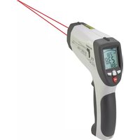
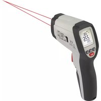
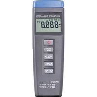
Controls
Illustration (fold-out page)
- Measuring input "+" and "-" , channel T1, for one K-type temperature sensor
- Measuring input "+" and "-" , channel T2, for one K-type temperature sensor
- Measuring input "+" and "-" , channel T3, for one K-type temperature sensor
- Measuring input "+" and "-" , channel T4, for one K-type temperature sensor
- Multi-function display with 4 x 4-digit display and display of functions and measuring units
- On/Off push-button, in secondary function to switch on and off the background lighting
- Push-button "HOLD" for keeping a measuring value (with rapidly changing measuring signals)
- Push-button "REL" (for relative value measurement = reference value measurement)
- Supply jack for connecting a suitable 9V DC adapter "-" inside
- Switch for changing the measuring unit from "°C" to "°F" and vice versa
- Serial RS-232 interface (3.5mm stereo jack bush), bi-directional
- "MAX MIN" – push-button for recording the maximum and minimum measuring values
- Push-button "T1 – T2" for displaying the temperature difference of channel 1 minus channel 2
- Threaded tripod bush
- Cover for the subjacent battery compartment
Table of Contents
Introduction 20
Prescribed Use 21
Controls (fold-out page). 22
Table of Contents 23
Safety Instructions....23
Presentation....25
Handling, Putting-into-Operation 26
Carrying out Measurements 31
Disposal. 32
Correcting Malfunctions 32
Maintenance and Calibration 33
Technical Data and Measuring Tolerances 34
Safety Instructions
The guarantees become invalid in the event of damage resulting from non-observation of the operating manual! We do not accept responsibility for such damage.
Moreover, we accept no responsibility for property damage or personal injuries caused by improper use or non-observance of safety instructions. Furthermore, in all such cases guarantees become invalid.
- To ensure safe operation the user has to observe the safety instructions and warning notes ("Warning!" und "Note!") contained in this operating manual. The following symbols are to be observed:

= Read the operating manual
- Measuring devices and accessories are no toys and must be kept out of reach of children in all circumstances!
- In industrial facilities, the safety regulations laid down by the professional trade association for electrical equipment and facilities must be adhered to.
- In schools, training facilities, do-it-yourself and hobby workshops, measuring devices and accessories are to be used only under supervision of trained personnel.
- When handling the thermometer take care that the measuring media are imperatively voltage less! Use special care when handling voltages over 25V AC and over 35V DC respectively. Even with these voltages you may suffer a life-threatening electric shock when touching electrical conductors.
- Before each measurement check your measuring device and the temperature sensors for damage(s).
- The voltage between measuring device and earth must by no means exceed 24V ACrms. and 60V DC resp.
- Do not work with the measuring device in rooms or under unfavourable ambient conditions where inflammable gases, fumes or dust are present or may be present. For your own safety prevent the measuring device and the measuring leads resp. from getting damp or wet by all means. Avoid operation in direct vicinity to
a) strong magnetic fields (loudspeakers, magnets)
b) electromagnetic fields (transformers, motors, coils, relays, contactors, electromagnets etc.)
c) electrostatic fields (charges/discharges)
d) transmitting antennas or high-frequency generators
- Do not use the digital thermometer shortly before, during or shortly after a thunderstorm (lightning stroke!/high-energy excess voltages!). Make sure that your hands, shoes, clothes, the ground, the measuring device and the measuring leads resp., the circuits and the circuit elements etc. are dry by all means.
-
If there is reason to believe that safe operation has become impossible, the device must be put out of operation and secured against unintended operation. It can be assumed that safe operation is no longer possible, if
-
the device shows visible damages
- the device no longer works and
- it was stored under unfavourable conditions for a long period of time or
- after extraordinary stress caused by transport.
- Never turn on the device immediately after it has been brought from a cold into a warm room. Condensation water that forms might destroy your device. Leave the device switched off and wait until it has reached room temperature.
Presentation
This Digital Thermometer 304 with PC-connection is equipped with several special features suitably supplementing the range of measurements:
With the "MAX MIN" function e.g. it is possible to establish and keep the respective highest or smallest occurring measuring value. With the function "HOLD" you can keep - rapidly - changing measuring
values (for the measuring protocol). With the bush button "T1 – T2" the difference from channel 1 – (minus) channel 2 is displayed. With the bush button "°C/°F" you may choose between two measuring units: the "English" in degree Fahrenheit and the one of the "remaining European" countries in degree Celsius. If you finally operate the push-button REL (with triangle symbol) the actual temperature display is set to "0.0" and only the difference (delta) is displayed. And with the switch-on push-button the background lighting can be switched on and off.
The measuring range extends from -200^ to +1370^ or from -328^ to +2498^ . The temperature range of the enclosed sensors however is limited to -50^ to +200^ ( -58^ to +392^ ).
The Digital 4-Channel Thermometer 304 is universally applicable in do-it-yourself and hobby workshops as well as in the professional area and in schools.
Handling, Putting-into-Operation
A Inserting of battery – exchanging of battery
In order to work properly your measuring device has to be equipped with a 9 V compound battery. When the battery exchange symbol appears in the left centre on the display you have to carry out a battery exchange. You do this in the following way:
- Disconnect your measuring device from the measuring circuit (and from the PC if connected or if any),
- remove the temperature sensors from the measuring device,
- switch it off and
- push the battery compartment cover carefully open in the direction of the arrow.
- Separate the used battery from the connecting clip and
- replace the battery by a fresh one of the same type.
- After changing the battery, put the connected battery into the battery compartment and
- close it again carefully.
- When closing the battery compartment make sure that the line of the connecting clip (read/black) is not squeezed.
Warning!
Never operate the measuring device when open!
Do not leave used batteries in the measuring device since even leakage-protected batteries may corrode and chemicals may be released hereby that are detrimental to your health or destroy the battery compartment.
Used batteries are to be considered as special waste and therefore have to be disposed of environmentally compatible. To this aim special collecting boxes are provided at your specialized dealer's shop or in the reusable waste facilities.
B Connecting the sensors
Whenever carrying out a measurement only use the temperature sensor specified for the purpose (in this case the K-type). Before making any connection check the state of the connector and the sensor end ("pearl") resp. and make sure that the insulation is intact.
Warning!
Always make sure that only the temperature sensor is exposed to the temperatures to be measured. Urgently bear in mind the safety instructions and the technical data concerning the working temperature. Never exceed the maximum input quantities.
C Putting-into-operation
C1 Basic Setting
With the coloured push-button "I" the measuring device is switched on and off. The device can equally be switched off by means of the
Auto-Power-Off function. Auto-Power-Off means an automatic switching-off of the device to the so-called "Sleep-Mode" (stand-by). The device switches off after approximately 30 minutes if
no push-buttons are operated or the Auto-Power-Off function has not been deactivated before.
The Auto-Power-Off function can be deactivated by way of operating the push-button "HOLD" at the same time when switching on the thermometer. An acoustic signal (twice in succession) indicates that the automatic switch-off has been deactivated.
If you want to switch off the measuring device before 30 minutes have elapsed you have to operate (keep pushed down) the push-button for 3 seconds. The display will show you a so-called "Count Down":
"P -0FF --- 3.....2.....1"
In secondary function the push-button serves to switch on/off the background lighting when lighting conditions are unfavourable. Since the lighting however has a relatively high energy consumption you should not use it too often.
Note!
The background lighting is switched off automatically after approximately 26 seconds.
C2 Push-Button Assignment
a) MAX MIN
By operating the push-button "MAX MIN" you switch over to the maximum and minimum value display. The occurring maximum and minimum temperatures of all inputs are constantly established and memorized.
The push-button "MAX MIN" being operated in individual steps the maximum value "MAX", the minimum value "MIN" or the actual
measuring value "MAX MIN" (flashing) are readable in turn. To leave the function operate the push-button "MAX MIN" for about 2 seconds.
Note!
During maximum/minimum/average value recording the measuring unit cannot be changed. Equally the function "REL" cannot be activated.
b) Push-button "T1 - T2"
With this push-button you determine which display is visible: the display of temperature T1 to T4 or the display of temperatures T1 and T2 (one beneath the other) or to the right of it the difference from T1 – (minus) T2.
c) HOLD function
Whenever pushing this button (briefly) you switch the HOLD function on or off. HOLD means that the actual measuring value is kept until the data-hold function is deactivated again. Switching over from °C to °F or vice versa is not possible. Nor are the activation of the time display or the "MAX MIN" function or the measurement of the reference value "REL".
d) Measuring of Reference Value "REL"
With the push-button REL the reference-value measurement is started. To this aim the actual temperature display (T1 to T4) is set to "0.0" independent of the measuring unit (°C or °F). Afterwards only the difference values are displayed. If afterwards the measured temperature at channel T1 is less e.g. by 5 degrees Celsius (°C), "-5°C" is displayed. If, however, afterwards the measured temperature at channel T1 is more by 25 degrees Fahrenheit, "25°F" is displayed. To return to the actual temperature display you have only to operate the push-button "REL" once more.
Note!
Whenever you push the button an integrated beeper will give you acoustic feedback in form of a short "beep".
e) Push-Button °C/°F
With the push-button "°C/°F" you change the measuring unit from degrees Celsius "°C" to degrees Fahrenheit "°F" and vice versa. This setting is not kept when the digital thermometer is switched off.
C3 Jack Assignment
a) Measuring Inputs
The measuring jacks T1, T2, T3 and T4 are so-called unipolar (+ and –) blade contact jacks. You have to connect the K-type temperature sensors to these jacks if you want to carry out temperature measurements according to the sensor specifications. Please note that the blade contacts of the connecting plugs are different in breadth.
Warning!
Never try to force the connecting plugs into the jacks when confused (+ and -)!
The jacks would be irretrievably destroyed and would have to be replaced.
b) Serial RS-232 Interface
The "OUTPUT" jack is a serial RS-232 interface in 3.5mm stereo jack format. The assignment is established as follows (connector plan):
At the back of the connector there is the ground =
GND = reference mass (=reference potential)
In the middle of the connector there is contact
RX = 5V High Input (= data input)
In front at the tip there is contact
TX = 5V High Output (= data output)
In order to make communication possible between the thermometer and an IBM-compatible PC, at first the prerequisite conditions have to be established:
A connection between PC and thermometer and the installation of the software.
Note!
The interface circuit as well as the software are optionally available as packages.
c) Connecting an Adapter
And finally jack 9V DC. Here an adapter with the following output data can be connected: 9V DC voltage, if possible stabilised, with an output current of at least 100mA, an external connector diameter of 1.35mm and an internal connector diameter of 1.35mm. The polarity: minus "-" inside, plus "+" outside.
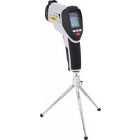
D Working Position
Always operate the Digital 4-Channel Thermometer 304 in a position that you can read the LCD display or that the digital display points to the top resp.
Via the tripod thread in the bottom part of the housing the measuring device can be fixed to a tripod.
Carrying Out Measurements
The temperature measuring range of the digital thermometer extends from -200^ to +1370^ for K-type sensors. The temperature range of the enclosed K-type sensors extends from -50^ to a maximum! of +200^ . Do not measure temperatures above +200^ ( = 392^ ) with the sensors enclosed.
Please bear in mind that "outside" the temperature range +18^ to +28^ (= range of guaranteed measuring accuracy) only the thermo element may be exposed to the temperature to be measured.
To carry out a measurement you proceed as follows:
- Connect according to your ideas either one or two or three or four temperature sensors (two enclosed) to the thermometer and switch it on.
Warning!
Do not apply any voltages. This may destroy the device.
- Hold the temperature sensor/sensors (line end/ends) at/into the voltageless measuring medium/media (dissipators and so on, but never corrosive or inflammable liquids!).
Note!
If the temperature sensors are not (correctly) connected or interrupted, "-" - - - " is displayed instead of a measuring value.
Disposal
If the Digital Thermometer 304 despite intact supply (9 V compound battery) is not ready for use or beyond repair it has to be disposed of in accordance with the relevant legal rules.
Correcting Malfunctions
With the Digital 4-Channel Thermometer 304 you have purchased a state-of-the-art product. Nevertheless problems or malfunctions may arise. Therefore you find in the following a description of how
you can correct some of these malfunctions yourself with relative ease; please observe the safety instructions in any case!
| Malfunction Possible Cause | |
| No display with the Has device switched on Has the | the battery been used up?the measuring device automaticallyswitched off after having been idle for 30 minutes? |
Maintenance and Calibration
To ensure the accuracy of the thermometer over a longer period of time it should be calibrated yearly.
The battery exchange is described under "Handling, Putting-into-Operation A". To clean the device or the display window please use a clean, non-linting, antistatic, dry cloth.
Warning!
Do not use carbon-containing cleaning agents, benzines, alcohols or the like as these attack the surface of the device. Furthermore, the fumes are detrimental to your health and explosive. Do not use sharp tools, screwdrivers, metal brushes, etc. for cleaning.
Technical Data and Measuring Tolerances
Technical Data
Display : 4-digit display up to 9999, with a 4-digit subdisplay, symbol display and measuring units
Maximum measuring rate . . . : 2.5 measurements per second, i.e. 5 measurements in 2 seconds
Working temperature
(ambient temperature). . . . . . : 0°C to +50°C (32°F to 122°F)
Storage temperature.....: -10°C to +60°C (14°F to 140°F, battery removed)
Relative air humidity .....: 0 to 80 %, non-condensing
Temperature for
guaranteed accuracy .....: +23°C ±5 K
Temperature coefficient . . . . : additionally 0.01% of reading
+0.03°C (resp. 0.01% of reading
+0.06°F) per K in the range of 0°C
to 18°C and from 28°C to 50°C
Battery exchange display . . . : "+ less than approx. 7.3V battery voltage
Battery type .....: NEDA 1604 9V or 6F22 9V (alkaline)
Weight.....: 210g (with battery)
Dimensions (I X b X h). . . . . . : 184 x 64 x 30mm (without wires)
Measuring tolerances
Indication of accuracy in ± (% of reading + display error in Kelvin "K") "K" for Kelvin stands as absolute value of a temperature difference or deviation.
Accuracy for the period of one year at a temperature of +23°C ±5K, at a relative air humidity of less than
80 %, non-condensing. The warm-up time is 1 minute.
| Measuring range Accuracy Resolution | |
| K-type measuring device-200°C to +199.9°C ±(0.2%+1.0K) 0.1°C+200°C to +399°C ±(0.5%+1.0K) 1°C+400°C to +1370°C ±(0.2%+1.0K) 1°C | |
| -328°F to -200°F ±(0.5%+2.0K) 1°F-199.9°F to +199.9°F ±(0.2%+2.0K) 0.1°F+200°F to+2498°F ±(0.3%+2.0K) 1°F | |
| K-type temperature sensor TP-K01-50°C to +200°C ±2.2K or ±0.75%-58°F to 392°F ±3.6K or ±0.75% | |
Warning!
Under unfavourable conditions exceeding the maximum admissible input quantities leads to damages to the measuring device or a threat to the life of the user!
F Introduction
Cher client,
"P -0FF --- 3.....2.....1"