Thermologger 309 - Thermometer VOLTCRAFT - Free user manual and instructions
Find the device manual for free Thermologger 309 VOLTCRAFT in PDF.
| Product type | 4-channel digital thermometer (Datalogger) |
| Brand | Voltcraft |
| Model | Thermologger 309 |
| Dimensions (L x W x H) | 184 x 64 x 30 mm (without cables) |
| Weight | 250 g (with battery) |
| Power supply | 9V battery type NEDA 1604 or 6F22, or 9V DC / 100 mA mains adapter (polarity - inside) |
| Measurement range | -200°C to +1370°C (type K sensors); -50°C to +200°C with supplied sensors |
| Resolution | 0.1°C up to 200°C, then 1°C |
| Accuracy | ±(0.2% + 1K) from -200°C to +200°C; ±(0.5% +1K) from +200°C to +400°C |
| Measurement channels | 4 (T1 to T4) for type K sensors |
| Main functions | Data recording (datalogger), MAX/MIN, HOLD, clock display, differential measurement T1-T2, RS-232 interface, °C/°F switching |
| Display | LCD 4 displays with 4 digits, symbols and units |
| Interface | RS-232 (3.5 mm stereo jack) for PC connection |
| Supplied software | CD with software for Windows 95/98/NT4.0 or later |
| Operating temperature | 0°C to +50°C |
| Storage temperature | -10°C to +60°C (without battery) |
| Relative humidity | 0 to 80% non-condensing |
| Safety | Do not use on live circuits; max voltage 24 VAC/60 VDC; avoid humid or explosive environments |
| Maintenance and cleaning | Clean with a dry, lint-free cloth; annual calibration recommended |
| Spare parts and repairability | Type K sensors, interface cable, mains adapter; repairs by qualified personnel |
| General information | 50-page instruction manual; CE compliance, DIN VDE 0411, EN 61010-1 |
Frequently Asked Questions - Thermologger 309 VOLTCRAFT
User questions about Thermologger 309 VOLTCRAFT
0 question about this device. Answer the ones you know or ask your own.
Ask a new question about this device
Download the instructions for your Thermometer in PDF format for free! Find your manual Thermologger 309 - VOLTCRAFT and take your electronic device back in hand. On this page are published all the documents necessary for the use of your device. Thermologger 309 by VOLTCRAFT.
USER MANUAL Thermologger 309 VOLTCRAFT
© Copyright 2008 by Voltcraft®
GB Impressum /legal notice in our operating instructions
These operating instructions are a publication by Voltcraft®, Lindenweg 15, D-92242 Hirschau/Germany, Phone +49 180/586 582 7 (www.voltcraft.de).
All rights including translation reserved. Reproduction by any method, e.g. photocopy, microfilming, or the capture in electronic data processing systems require the prior written approval by the editor. Reprinting, also in part, is prohibited.
These operating instructions represent the technical status at the time of printing. Changes in technology and equipment reserved.
© Copyright 2008 by Voltcraft®
© Copyright 2008 by Voltcraft®
01_1108_02/HK
GB The present operating instructions form part of this product. They contain important information on how to put the product into operation and how to operate it. Please take this into consideration when you pass it on to third parties.
Keep these operating instructions for future reference.
The table of contents on page 21 indicates the topics and the relevant page numbers
text_image
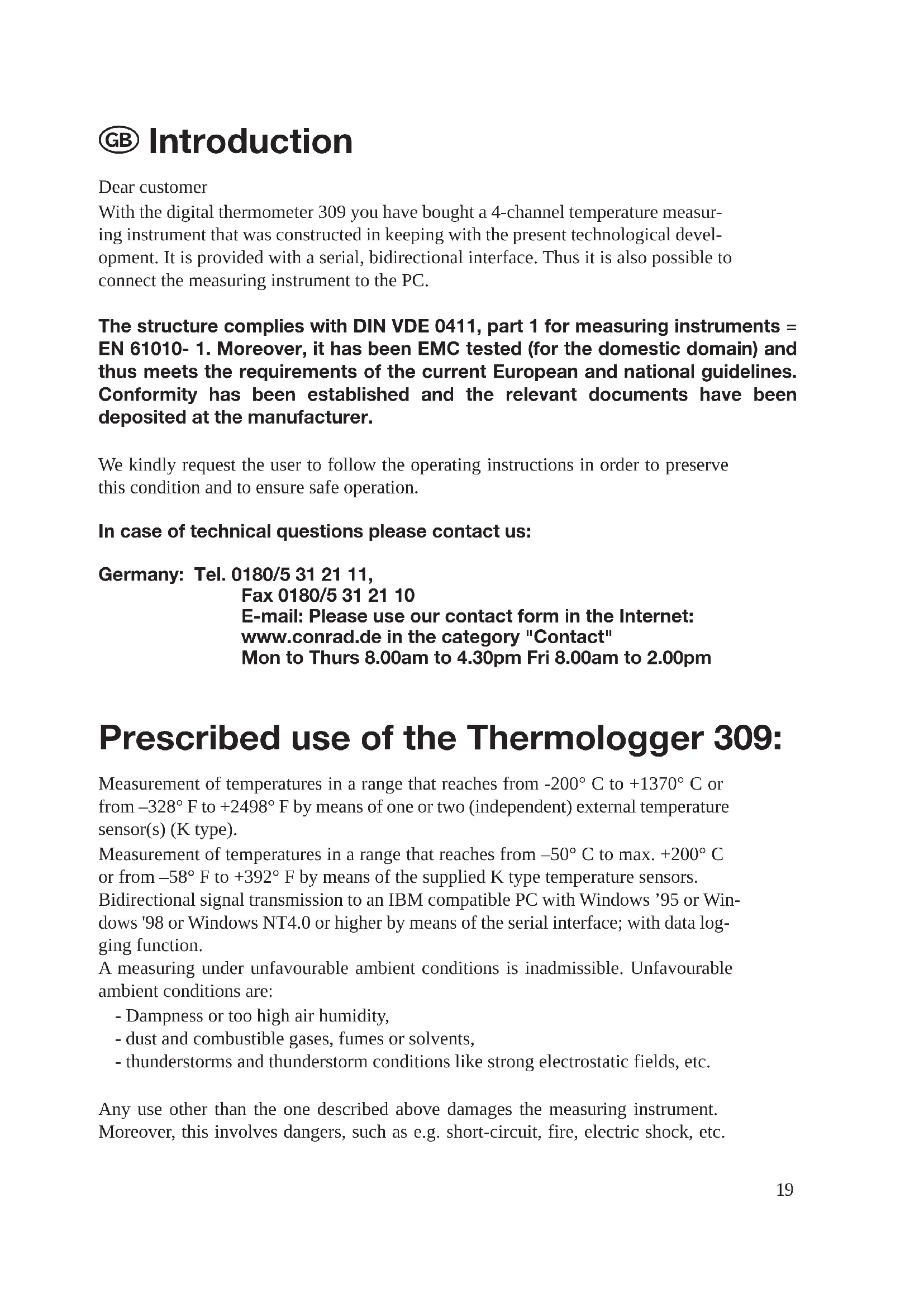
T1 T2 T3 T4 1000 1000 1000 1000 DIG T1-T2 SETUP HOLD MAC MW CLOCK MTV REC °C/°F ▲ ▼ RAVOE -208°C ~ 1370°C -328°F ~ 2491°F POWER-UP OPTIONS 6 7 8 9 10 11 T1 T2 T1 T2 T1 T2 T1 T2 T1 T2 T1 T2 T1 T2 T1 T2 T1 T2 T1 T2 T1 T2 T1 T2 T1 T2 T1 T2 T1 T2 T1 T2 T1 T2 T1 T2 T1 T2 T1 T2 T1 T1 T1 T1 T1 T1 T1 T1 T1 T1 T1 T1 T1 T1 T1 T1 T1 T1 T1 T1 T1 T1 T1 T1 T1 T1 T1 T1 T1 T1 T1 T1 T1 T1 T1 T1 T1 T1 T1 T1 T1 T2 T1 T2 T1 T2 T1 T2 T1 T2 T1 T2 T1 T2 T1 T2 T1 T2 T1 T2 T1 T2 T1 T2 T1 T2 T1 T2 T1 T2 T1 T2 T1 T2 T1 T2 T1 T2 T1 A50000000000000000000000000000000000000000000000000000000000000000000000000000000000000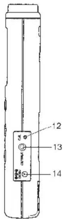
text_image
12 13 14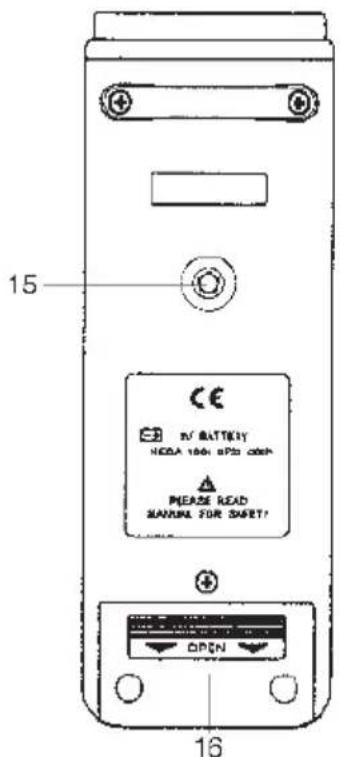
text_image
15 CE RV BATTERY HOLD 100% SP30 000# PLEASE READ MANUAL FOR SAFE! OPEN 16D Einführung
Sehr geehrter Kunde
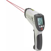
With the digital thermometer 309 you have bought a 4-channel temperature measuring instrument that was constructed in keeping with the present technological development. It is provided with a serial, bidirectional interface. Thus it is also possible to connect the measuring instrument to the PC.
The structure complies with DIN VDE 0411, part 1 for measuring instruments = EN 61010-1. Moreover, it has been EMC tested (for the domestic domain) and thus meets the requirements of the current European and national guidelines. Conformity has been established and the relevant documents have been deposited at the manufacturer.
We kindly request the user to follow the operating instructions in order to preserve this condition and to ensure safe operation.
In case of technical questions please contact us:
Germany: Tel. 0180/5 31 21 11,
Fax 0180/5 31 21 10
E-mail: Please use our contact form in the Internet:
www.conrad.de in the category "Contact"
Mon to Thurs 8.00am to 4.30pm Fri 8.00am to 2.00pm
Prescribed use of the Thermologist 309:
Measurement of temperatures in a range that reaches from -200^ C to +1370^ C or from -328^ F to +2498^ F by means of one or two (independent) external temperature sensor(s) (K type).
Measurement of temperatures in a range that reaches from -50^ C to max. +200^ C or from -58^ F to +392^ F by means of the supplied K type temperature sensors.
Bidirectional signal transmission to an IBM compatible PC with Windows '95 or Windows '98 or Windows NT4.0 or higher by means of the serial interface; with data logging function.
A measuring under unfavourable ambient conditions is inadmissible. Unfavourable ambient conditions are:
- Dampness or too high air humidity,
- dust and combustible gases, fumes or solvents,
- thunderstorms and thunderstorm conditions like strong electrostatic fields, etc.
Any use other than the one described above damages the measuring instrument. Moreover, this involves dangers, such as e.g. short-circuit, fire, electric shock, etc.
No part of the product may be modified or rebuilt. Always observe the safety instructions.
Controls
Illustration (fold-out page)
- Measuring input "+" and "-" , channel T1, for a K type temperature sensor
- Measuring input for channel T2, for a K type temperature sensor
- Measuring input for channel T3, for a K type temperature sensor
- Measuring input for channel T4, for a K type temperature sensor
- Multifunctional display with 4 x 3-digit sub displays (smaller displays) and display of the functions and measuring units
- On / Off button, serves in second function in connection with the "T1 - T2" button as key for the setup "Set"
- T1 - (minus) T2 button
- "HOLD" button serves to hold a measuring value (in case of quickly changing measuring signals), serves in second function as "Clock" button to indicate the set time
- "MAX MIN" button serves to record the minimum value, maximum value and average value, serves in second function as INTV button
- Record button "REC", serves in second function to change the settings in upward direction (increase)
- Change button serves to change the measuring unit from "°C" to "°F" and vice versa, serves in second function to change the settings in downward direction (decrease)
- Trimmer for the offset calibration
- Serial RS-232 interface (3,5 mm stereo jack bush)
- Supply jack for the connection of a suitable network adapter "-" inside
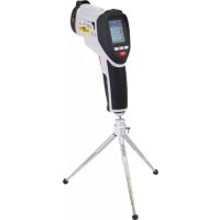
- Threaded tripod bush
- Cover for the battery chamber lying underneath it
Table of contentsx
Introduction 19
Prescribed use....19
Controls (fold-out page) 20
Table of contents 21
Safety instructions ....21
Presentation 23
Handling, putting-into-operation 23
Connection of the PC, installation of the software 27
Carrying out measurements....28
Disposal 31
Correcting malfunctions....31
Maintenance....32
Technical specifications, measuring tolerances 32
Safety instructions

We do not assume liability for damages to property or personal injury which are caused due to improper use or due to failure to observe these operating and safety instructions. In such cases the guarantee will expire.
- The digital thermometer 309 left the works in technically reliable condition. In order to preserve this condition and to ensure safe operation, we kindly request the user to observe the safety instructions and the warning notes ("Warning!" and "Note!") of these operating instructions. The following symbols need to be observed:

= Read the operating instructions
- Keep measuring instruments and accessories out of reach of children. They are nothing to play with.
- In commercial and industrial facilities the regulations for the prevention of accidents as laid down by the professional trade association for electrical equipment and devices need to be observed.
- In schools, training facilities, do-it-yourself and hobby workshops the measuring instruments are to be used under the responsible supervision of trained personnel.
- Make sure when handling the thermometer that the measuring media are absolutely dead! The utmost caution is advised when dealing with voltages that exceed 25 V AC or 35 V DC. Even at these voltages you may get an electric shock that is dangerous to life if you touch the electrical conductors.
- Make sure before each measuring that neither your measuring instrument nor your temperature sensors are damaged.
- Make absolutely sure that the voltage between measuring instrument and earth does not exceed 24 VACrms or 60 VDC.
- Do not use the measuring instrument under unfavourable ambient conditions or in rooms that contain or may contain combustible gases, fumes or dusts. Make sure for your own safety that neither the measuring instrument nor the measuring leads get damp or wet. Avoid operation in the immediate vicinity of
a) strong magnetic fields (loudspeakers, magnets)
b) electromagnetic fields (transformers, motors, coils, relays, contactors, electromagnets, etc.)
c) electrostatic fields (charges / discharges)
d) transmitting antennas or HF generators
- Do not use the digital thermometer just before, during or shortly after a thunderstorm (lightning stroke! / high-energy over-voltages!). Ensure that your hands, shoes, clothes, the floor, the measuring instrument and the measuring leads, circuits and circuit elements are absolutely dry.
- If there is reason to believe that safe operation has become impossible, put the device out of operation and secure it against unintended operation.
Safe operation must be presumed to be no longer possible if
- the device exhibits visible damages
- the device does not function any more
- the device was stored under unfavourable conditions for a long period of time or
- the device was exposed to extraordinary stress caused by transport.
- Never turn-on the measuring instrument immediately after it has been brought from a cold into a warm room. Under unfavourable conditions, the condensation water that forms may destroy your device. Leave the device turned-off until it has reached room temperature.
Presentation, system prerequisite(s)
This digital thermometer 309 with PC connection is equipped with several special features which complete some measuring in a significant way:
With the function "MAX MIN" you can, for example, detect and record the maximum or the minimum measuring value that appears. With the function "HOLD" it is possible to record quickly changing measuring values (for the measuring protocol). The recording of the measuring values is started with the button "REC". With the button "° C/° F" you can choose between two measuring units: the "English" unit in Fahrenheit and the unit used in the "remaining European countries" in Celsius. If you actuate the button "T1 - T2" during the turning-on, you will get to the setup menu. Further information will be given later. By means of the supplied interface circuit (serial), a bidirectional connection to the PC is made. After the installation of the relevant software on the PC, the digital thermometer and the PC can communicate. The following requirements must be met for installing and using the software:
At least 486 DX2/100 with 16 MB RAM or faster/bigger
At least Windows '95 or '98 or NT 4.0 or higher
A CD ROM drive, a resolution of at least 800 x 600
And finally approx. 7 MB free fixed-disk storage
The measuring range reaches from -200^ C to +1370^ C or from -328^ F to +2498^ F. The temperature range of the supplied sensors, however, is limited to a range that reaches from -50^ C to +200^ C. The digital thermometer 309 can be used universally for hobby, profession or school purposes, etc.
Handling, putting-into-operation
A Insertion of the battery – Replacement of the battery
Your measuring instrument must be equipped with a 9 Volt battery to function correctly. When the battery replacement symbol appears at the top on the left of the display, the battery must be replaced. Proceed as follows:
- Disconnect your measuring instrument from voltage circuit and PC,
- remove the temperature sensors from the measuring instrument,
- turn it off and
- remove the battery chamber cover pushing it carefully in arrow direction.
- Disconnect the used battery from the connecting clip and
- replace the battery with a new battery of the same type.
- Insert the connected battery into the battery chamber after completed replacement of the battery and
- close the battery chamber carefully.
- Ensure not to squash the cable of the connecting clip (red/black) when closing the battery chamber.

Never operate the measuring instrument when it is open.
Do not leave the used batteries in the measuring instrument. Even leakage-protected batteries may corrode. The chemicals which may be set free damage your health and the battery chamber.
Defective, used batteries are to be considered as special waste and must be disposed of in an environmentally compatible way. Used batteries can be given back free of charge at the collecting boxes provided by your municipality, at our branches or at the shops that sell batteries and accumulators. There you can find specially marked collecting boxes. It is not permitted to put used batteries into the normal domestic waste.
B Connection of the temperature sensors
For your measurements, make only use of temperature sensors that are specified for this purpose (in this case K type). Always examine the connectors and the sensor ends ("pearls") before use and make sure that the insulation is not damaged.

Always ensure to expose only the temperature sensors to the temperatures that are to be measured. Always observe the safety instructions and the technical specifications concerning the working temperature. Never exceed the max. input quantities.
C Putting-into-operation
C1 Basic setting
The measuring instrument is turned-on and turned-off with the colour button "I" (in the circle).
For turning-off the device it is necessary to keep the button pressed until the display disappears (... 3... 2... 1... off). The device can also be turned-off by means of the automatic power-off function. Automatic power-off means that the device is automatically set to the so-called "sleep mode" ("stand-by"). The device will be turned-off after approx. 30 minutes provided that
there are no buttons actuated or that
the measuring instrument does not do any recordings of measuring values (REC) or that
the automatic power-off function has not been turned-off before.
If you want to turn-off the automatic power-off function, actuate the Hold button at the same time when you turn-on the thermometer. The symbol " indicates that the automatic turning-off has been deactivated.
C2 Button assignments
a) MAX MIN for the temperature measuring input "T1"
By actuating the button "MAX MIN" you get to the recording of the minimum and maximum values. The highest and lowest temperatures are constantly detected and recorded. With each actuation of the button you can read alternately the maximum value "MAX", the minimum value "MIN" or the current measuring value "MAX MIN" (flashing). Actuate the button "MAX MIN" for approx. 2 seconds in order to quit the function.
Note!
It is not possible to change the measuring unit during the recording of the maximum / minimum values.
b) CLOCK for the time display
The actual date with year (centre), month, day (at the bottom on the left) and time (hours:minutes, at the bottom on the right) are indicated with the button "CLOCK" (after setting the time). Each press of the button is confirmed with a short "Beep" of the beeper.
In order to set the time, proceed as follows:
Actuate the button "T1 - T2" at the same time when you turn-on the thermometer in order to set the time. In that way you will get to the setup menu "Set".
Now actuate the button "CLOCK" (= Hold). The display for the date and the time appears, the year is flashing. With the buttons "^" for upwards (= "REC") and "v" (= "°C/°F") for downwards you can modify the setting upwards or downwards.
Set the year and actuate the button "CLOCK" once.
Now the segments for the month are flashing.
Set the actual month (e.g. 01 for January) and actuate the button "CLOCK" once again. Now the segments for the day are flashing.
Set the actual day (e.g. 08 for the eighth day of the month) and actuate the button "CLOCK" once. Now the segments for the hours are flashing.
Set the hours (24-hour display) of the actual time and actuate the button "CLOCK" once. Now the segments for the minutes are flashing.
Set the minutes and actuate the button "CLOCK" once in order to finish the setting of the time. The display indicates for a short time the available memory (e.g. 1 5984 for 15984 memory locations). Then the display changes to the "normal" temperature display.
Now the time is set relative exactly to the minute.
c) HOLD function
With each press of the button (brief) the HOLD function is activated or deactivated. HOLD means that the current measuring value of T1 is held until the data hold function will be deactivated. While the measuring value of T1 stands still, the temperature difference T1- T2 and the temperature display T2 continue running. It is neither possible to change from °C to °F or vice versa nor to activate the time display or the function "MAX MIN".
d) Data logger, recording of measuring values
The recording of the measuring values is started with the REC button. Every 5s (adjustable, recording interval), for example, the measuring values are recorded (T1, T2, T3 and T4) with time registration. The values are filed at a memory location. You can see the values in the data logger window of the computer.
Proceed as follows to set the recording interval:
Actuate the button "T1 - T2" at the same time when you turn-on the thermometer and you will get to the setup "Set". Now actuate the button "MAX MIN" once. After that, there will appear "Int" for Interval and a flashing minute display. Now set the desired recording interval in minutes and seconds. The maximum recording interval is 59 minutes and 59 seconds. The minimum value is limited to "00: 01" (= 1s). Actuate the "MAX MIN" button once again after completed setting and you will get back to the current temperature measuring display.
Note!
Each press of a button is confirmed with a short "Beep" of the installed beeper.
C3 Jack assignment
The jacks T1 to T4 are so-called unipolar blade contact jacks. You must connect the K type temperature sensors to these jacks if you want to carry out temperature measurements according to the sensor specifications. Take into account that the blade contact jacks have different widths.

Never try to squeeze the connectors the wrong way (+ and - mixed up) with force into the jacks. The jacks would be destroyed definitely and should be replaced.
The jack "OUTPUT" is the serial RS-232 interface in 3,5 mm stereo jack format. The assignment can be defined as follows (connector plan):
At the back of the connector there is the ground = GND = reference mass (= reference potential)
In the centre of the connector there is the contact RX = 5 V high input (= data input)
At the front at the point there is the contact TX = 5 V high output (= data output)
And finally there is the jack DC 9V. You can connect here a power supply unit with following output data: 9 V direct voltage, if possible, stabilised, with an output current of at least 100 mA, a connector outside diameter of 3.5 mm and a connector inside diameter of 1.35 mm. The polarity: minus "-" inside, plus "+" outside.
D Working position
Always operate the digital thermometer 309 so that you can read the liquid-crystal display (LCD) or that the digital display points upwards.
Connection of the PC, installation of the software
The communication between the thermometer and an IBM compatible PC can only take place if the following requirements are met:
- a connection between PC and thermometer and
- the installation of the software
Concerning 1.
Connect the supplied interface circuit to the 9-pole sub D jack "COM 1" at the turned-off PC and then to the 3,5 mm stereo jack bush at the thermometer. Now check the safe fit of the plug-in connection and turn-on both the thermometer and the PC.
Concerning 2.
There is a CD attached to the data logger digital thermometer 309. The software that can be found on this CD now needs to be loaded on the PC. Put the CD into the relevant CD-ROM drive of the PC and close the drive. Now the automatic setup starts. Follow the instructions on the screen and finish the installation with a restart "Finish"
or
Click the Start button and then the field "Programs". Click the field "Windows-Explorer" right at the bottom. Now click in the Windows-Explorer the field "D" or "E" or "F" or something like that depending on the designation of your CD-ROM drive. The contents of the CD are indicated. Double click the Icon "Setup".
Now the setup takes place. Follow the instructions on the screen:
First "Initializing" (basic elements) => window "ThermoLog" => "Welcome....." => "Components"- Selection => file designation in the start window => "Copying installation files" => "Reboot windows" with "finish".
After completed installation and restart, open the file "Programs" and click there "Test Link" => "Se 309" and finally once again "Se 309".
Now the working window appears more or less quickly (depending on the working storage and the speed of your computer). Further information will follow in the next chapter.
Carrying out measurements, data transmission
Data transmission
A) In general
We are still in the working window. On the left, there is the illustration of the thermometer and perhaps "No Connection" provided that the thermometer has been turned-off or disconnected.
Turn-on the thermometer or connect it. Now the message "No Connection" disappears. If the message "No Connection" does not disappear, there is a problem either with the thermometer (battery?) or with the connecting cable (safe fit?) or with the software installation (setup error?). Start again from the beginning and try it once more.
In the working window you can click everywhere where a "readable" button can be seen. In the headline of the menu window you can find the following fields:
The field "File" for Save, Print or Exit for quitting the program or
The field "Real Time" (graph), a graphic presentation of the measurement in real time (Run or Stop) or
The field "Datalogger", the transmission of the stored data from the thermometer to the PC or
The field "View" for activating and deactivating the Control Panel or the graph or The field "Window" for activating or deactivating different window views (cascading windows) or
The field "Com Port" for setting up the interface if the Com 1 is "occupied" or
The field "Help", the so-called help file with a German menu-driven operation but an English help text or
Finally the field "Exit" (a "X" at the top on the right) for quitting the program.
In the bottom line of the working window you can follow the status of the Thermologist: "On Connection" for "the connection has been established" or "Off Connection" for "the connection has been interrupted".
B) Real time graph
Click the field "Real Time" and "run". If you have a colour display or a colour monitor, you will see four constantly writing lines that depict the temperatures T1 (in yellow), T2 (in red), T3 (in green) and T4 (in pink) in dependence on the time T. In the following you will find a short description of the different commands.
The two fields on the left in the real time graph window serve to fade in or fade out the table below the temperature writing or to fade in or fade out the three fields Start-Time, Sampling Rate and Data-No. (= continuous counter of the acquired tempera-
ture data). The max. setting time of the Sampling Rate is 59 minutes and 59 seconds. The shortest setting is 2s, that means every 2 s there are new screen contents appearing (new measuring values).
The three buttons to the right of them for the "Normalcursor" (arrow symbol) the so-called X-marker to set X-markings and the "T" for a text comment in the stopped temperature writing.
To the right of it, there is the Clear button which serves to delete made settings.
To the right of it, there is the button for "Undo Zoom". If you have zoomed a detail with the mouse (keep the left mouse key pressed) you can now undo this zoom with the "Undo Zoom".
To the right of it (between "Undo Zoom" and "Graph Options"), there is a inconspicuous field "Split". If you click this field, the measuring depiction will be split from one-channel presentation to four-channel presentation and vice versa.
Graph Options
If you click this field, you will get to a further window which is called "Customization". With this field and the contained field commands you can create a main and a subtitle in different founts, change the background colour, make the grid lines disappear, etc.
Y- Axis
When you click this field, you can define the temperature depiction range, e.g. from -20^ to +60^ or -50^ to +200^ . The unit depends on the thermometer setting, the bigger the range, the less exact the depiction.
If you want to close the window "Real- Time Graph", click the "x" at the top on the right in the menu "Graph".
Below the "screen" with the continuous temperatures (channel 1 to 4) there is a table that registers the lowest and the highest appearing temperatures of each channel with time. Stop the measuring writing and the average value AVG can be seen, too. In that way you can, for example, find out at what time a temperature has changed at which sensor in which way.
C) Data Logger
If you click this window symbol, you will see two submenus: "Load" to start the data logger and "Setup" for the alignment of the measuring instrument to the PC (time synchronous etc.). Click "Load" and there will appear a mix of "Real-Time-Graph", a "MAX MIN" depiction (below) and a display of "Data Sets" (data records) to the left of it. Click one of these data records and the contents will be depicted on the screen, provided that they have been filed. At the bottom you see the maximum value (MAX)
and the minimum value (MIN) from T1 to T4. With the left mouse key (keep it pressed) and the mouse cursor you can zoom details of the graphics. With the "Undo Zoom" you can undo the zoom. The depiction of the table "Tabular" has already been described sufficiently.
D) View
Click the field "View" and there "Control Panel". Now the front of your thermometer 309 is depicted with changing display. On a limited scale (no setup settings) you can now operate your thermometer from the PC with the mouse. If you click the real time graph, however, the screen is filled with the real time display. Click the "x" at the top on the right in order to close the window "Real Time Graph".
E) Window
Click "Window" and there Tile for the total view or Cascade for a minimised view. Click "Panel" for the Thermologist (front) in the foreground or "Real-Time-Graph" for the real time measurement in the foreground or, if activated, "Data Logger" for the data log depiction in the foreground.
F) HELP
If you click this symbol (question mark above a book) you will get to the described help menu.
Carrying out a measurement
In general:
The temperature measuring range of the digital thermometer reaches from -200^ C to +1370^ C.
The temperature range of the supplied sensor reaches from -50^ C to max.! 200^ C. Do not measure temperatures that are higher than +200^ C (= 392^ F) with the supplied sensor.
Take into account that "outside" the temperature range +18^ C to +28^ C (= range of the guaranteed measuring accuracy) it is only permitted to expose the thermoelement to the temperature that is to be measured.
Measuring:
Proceed as follows to measure the temperature:
- Connect, depending on the demand, either one or two or four K type temperature sensors (you find two attached) to the thermometer an turn it on.

Do not connect any voltages. This might destroy the device.
- Hold the temperature sensor/s (wire end/s) at/into the dead measuring medium (heat sink etc., but no caustic or combustible liquids!).
Notes!
The temperature of T1 is displayed in the left upper display. In the right upper display the temperature of T2 is displayed. Below them on the left and on the right, the temperatures of the inputs T3 and T4 are displayed.
If one of the four temperature sensors is not connected or if it is interrupted, the signs "-" will be displayed instead of a measuring value. In this case the difference will not be detected/displayed.
- Now, when the two inputs T1 and T2 are occupied, it is possible to measure the difference temperature. Actuate the button "T1 - T2". Now the temperature T1 is displayed at the top on the left, T2 at the bottom on the left. "1 - 2" can be read at the top on the right and the difference of T1 minus "-" T2 is displayed at the bottom on the right.
Disposal
If the digital thermometer 309 does not function any longer or cannot be repaired any more despite correct supply (9 Volt battery), ensure to dispose of the device according to the relevant statutory requirements.
Correcting malfunctions
The digital thermometer 309 you have bought was constructed in keeping with the present technological development. Nevertheless, there may arise problems or malfunctions. For this reason, the following chapter will give you information on how to correct some of these malfunctions rather easily.

Observe the safety instructions!
| Error Possible cause | |
| No transmission to the PC Safe | contact of the connecting cable?Software loaded according to the instructions?PC interface all right? |
| No display at the Is the battery turned-on device Did the measuring instrument turn-off automatically after 30 minutes of non-use? | discharged? |
Maintenance and calibration
In order to ensure the accuracy of the thermometer for a longer period of time you should calibrate it once a year.
The replacement of the battery is described in the chapter "Handling, putting-into-operation A". Clean the device and the window of the display with a clean, lint-free, antistatic and dry cleaning cloth.

Do not use cleaning agents that contain carbon or benzines, alcohol or anything similar to clean the product since these substances damage the surface of the measuring instrument. Moreover, these fumes are hazardous to the health and explosive. Do not use tools with sharp edges, screwdrivers, metal brushes or anything similar to clean the device.
Technical specifications and measuring tolerances
Technical specifications
Display : 4 x four-figure displays up to max. 9999,
symbol displays and measuring units
Max. measuring rate : 1,25 measurements per second, that are
5 measurements in 4 s
Working temperature
(surroundings of the
measuring instrument) : from 0^ C to +50^ C (from 32^ F to 122^ F)
Storage temperature : from -10^ C to +60^ C (from 14^ F to
140°F, battery removed)
Relative air humidity : from 0 to 80 %, not condensing
Temperature for guaranteed accuracy : from +23°C ±5 K
Temperature coefficient : further 0,01% of the reading +0,03°C (or
0,01% of the reading +0,06° F) per K in a
range reaching from 0^ C to 18^ C and
from 28°C to 50°C
Battery replacement indication : " " from below approx. 7,3 V battery voltage
Battery type : NEDA 1604 9V or 6F22 9V (alkaline)
Weight : 250 g (with battery)
Dimensions (L X W X H) : 184 x 64 x 30 mm (without lines)
Measuring tolerances
Indication of the accuracy in ± (%) of the reading + indication error in Kelvin "K") "K" for Kelvin stands as absolute value of a temperature difference or deviation.
Accuracy for 1 year at a temperature of +23°C ±5K, at a relative air humidity lower than 80%, not condensing. The warm up time is 1 minute
Measuring range of the Accuracy Resolution measuring instrument:
From -200^ to +200^ ± (0,2% + 1K) 0,1^
From +200°C to +400°C ±(0,5%+1K) 1°C
From +400°C to +1370°C ±(0,2%+1K) 1°C
From -328^ to -200^ ± (0,5% +2^) 0,1^
From -200^ to +200^ ± (0,2% +2^) 0,1^
From +200° F to +2498° F ±(0,3%+2°F) 1°F
Temperature sensor TP- K01
From -50^ to +200^ ± 2,2K or ± 0.75%
From -58° F to 392° F ±3,6K or ±0,75%

Exceeding the max. admissible input quantity may damage under unfavourable conditions the measuring instrument and may be hazardous to the user's life.
F Introduction
Cher client,