CO100 - Gas detector VOLTCRAFT - Free user manual and instructions
Find the device manual for free CO100 VOLTCRAFT in PDF.
| Product type | CO₂ gas detector (carbon dioxide) |
| Brand | Voltcraft |
| Model | CO100 |
| Dimensions (approx.) | 130.6 x 85 x 59 mm (height x width x depth) |
| Weight | 180 g |
| Power supply | Mains adapter 100-240 V AC / 6 V DC 300 mA (included) or external 6 V DC supply via internal terminals (300 mA min) |
| CO₂ measurement method | NDIR (non-dispersive infrared absorption) |
| CO₂ measurement range | 0 to 3000 ppm |
| CO₂ accuracy | ±75 ppm or ±5 % (0-2000 ppm); ±7 % (>2000 ppm) over 5 years |
| Temperature range | 0 °C to +50 °C |
| Temperature accuracy | ±1 °C (±1.5 °C in a draft) |
| Humidity range | 20 % to 90 % RH |
| Humidity accuracy | ±5 % RH at +23 °C |
| Display | LCD screen with backlight (not specified) |
| LED indicators | 3 LEDs: green (< threshold 1), yellow (between thresholds), red (> threshold 2) |
| Audible alarm | Yes, adjustable (can be muted) |
| Alarm thresholds | 2 adjustable thresholds (threshold 1 default 800 ppm, threshold 2 default 1200 ppm) |
| Altitude compensation | Yes, adjustable in meters (0-? m) |
| Data logger | 48 data sets (CO₂, temperature, humidity) every 30 min over 24 h |
| MAX/MIN display | Yes, with reset possible |
| Relay output | NO (normally open) contact max. 30 V DC / 2 A, activated if threshold 2 exceeded |
| Ventilation rate | Calculated (l/s/p or m³/h/p) based on CO₂ |
| Maintenance | Clean with a soft, dry cloth; do not use aggressive detergents; do not disassemble |
| Safety | Do not expose to moisture; use only the supplied adapter; do not modify; keep out of reach of children; risk of electric shock |
| Repairability | Repairs entrusted to a specialist; no spare parts listed |
Frequently Asked Questions - CO100 VOLTCRAFT
User questions about CO100 VOLTCRAFT
0 question about this device. Answer the ones you know or ask your own.
Ask a new question about this device
Download the instructions for your Gas detector in PDF format for free! Find your manual CO100 - VOLTCRAFT and take your electronic device back in hand. On this page are published all the documents necessary for the use of your device. CO100 by VOLTCRAFT.
USER MANUAL CO100 VOLTCRAFT
text_image
CO₂ 650 TEMP 25.4°C RH 60% A B C D E F G H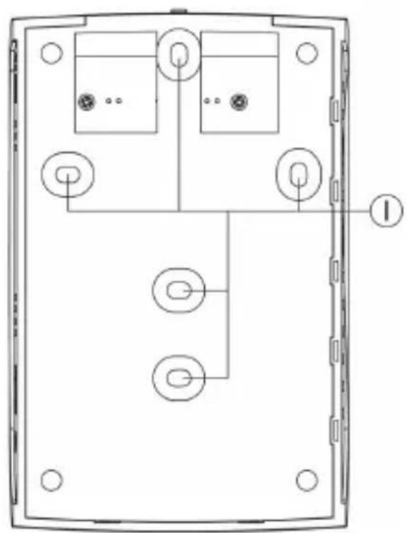
natural_image
Technical line drawing of a device rear panel with internal components and mounting holes (no text or symbols)A LC-Display
B Grüne LED
C Gelbe LED
D Rote LED
E Taste „MODE“
F Taste „▲“
G Taste „▼“
H Taste „ENTER“
text_image
M CO₂ 650 °C TEMP 25.4°C RH 60% J K Lnatural_image
Technical line drawing of an open computer case with internal components and a scroll arrow indicating rotation (no text or symbols present)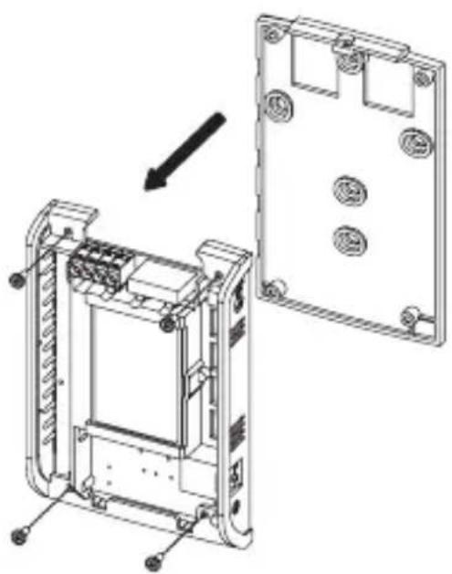
natural_image
Technical line drawing of a device housing assembly showing internal components and mounting holes (no text or symbols)- Introduction ...... 24
- Intended Use 25
- Scope of Delivery 26
- Explanation of Symbols 26
- Safety Information 27
- Controls Elements 29
- Wall Installation and Connection 30
- Start-Up 32
- Operation 33
a) Muting the Signal Sound 33
b) Setting Threshold Value 1 34
c) Setting Threshold Value 2.... 34
d) Setting Altitude (Altitude Compensation) 35
e) Setting the Carbon Dioxide Normal Value in the Outside Area 35
f) Calibration 36
g) Datalogger Function (Data Memory) 37
h) Displaying/Resetting MAX/MIN Values 38
i) Resetting the CO _2 Meter to Factory Settings 39
j) Displaying Temperature/Ventilation Rate 40
- Maintenance and Care 41
- Disposal 41
- Technical Data 42
a) CO_2 Meter 42
b) Mains Adapter 43
1. INTRODUCTION
Dear Customer,
Thank you for making the excellent decision of purchasing this Voltcraft® product.
Voltcraft® - This name stands for above-average quality products in the areas of measuring, charging and grid technology, characterised by technical competence, extraordinary performance and permanent innovation.
Whether you are an ambitious hobby electronics technician or a professional user - a product of the Voltcraft® brand family will provide you with the best solution for even the most sophisticated of tasks. Special features: We offer the sophisticated technology and reliable quality of our Voltcraft® products at a near-unbeatable price/performance ratio. We lay the groundwork for long, good and successful cooperation.
Enjoy your new Voltcraft® product!
All company names and product names are trademarks of their respective owners. All rights reserved.
2. INTENDED USE
The product is a stationary CO_2 meter for determination of the carbon dioxide concentration ( CO_2 ) in the ambience air with the precise and long-term stable NDIR measuring method (non-dispersive infrared absorption measurement).
The meter is used to monitor the carbon dioxide content in the room air so that the corresponding ventilation measures can be initiated early on. Increased CO_2 content leads to exhaustion, lack of focus and performance deficits.
A carbon-dioxide alarm value can be set individually by the user. If this value is exceeded, it will trigger an acoustic alarm. Three LEDs indicate the current CO_2 content at a single glance.
This display can show not only the CO_2 concentration but also the air temperature and humidity.
A datalogger records the measured CO_2 concentration values for the last 24 hours (and the corresponding temperatures and humidities) at 30-minute intervals. Maximum and minimum values can also be displayed.
The included mains adapter can be used to supply the CO_2 meter with power. Two internal screw terminals can be used to connect another external voltage/current supply (stabilised direct voltage of 6 V/DC is required, as well as a current of at least 300 mA).
Special features are a relay switching output inside the casing (NO contact, closer) that is activated when the upper threshold value is exceeded (for relay load capacity, see chapter „Technical Data“).
This product is not suitable for other types of use. Any other use may damage the product, including the associated dangers like short circuit, fire, electric shock, etc. Observe the safety information under all circumstances!
3. SCOPE OF DELIVERY
- CO_2 meter
- Mains adapter
- Operating instructions
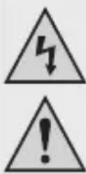
4. EXPLANATION OF SYMBOLS
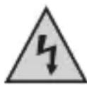
The triangle containing a lightning symbol warns against danger of electric shock or impairment of the electrical safety of the device.
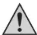
An exclamation mark in a triangle indicates important notes in these operating instructions that should be strictly observed.
→ The „arrow“ symbol can be found when there is special advice and notes regarding the operation.
In case of damage caused by non-compliance with these operating instructions, the warranty/guarantee will expire. We do not assume any liability for consequential damage!
We do not assume any liability for damage to property or personal injury caused by improper use or the failure to observe the safety instructions! In such cases the warranty/guarantee will expire.
Dear Customer,
this safety information serves not only to protect the product, but also your own safety and the safety of other persons. Therefore, read this chapter very carefully before taking the product into operation!
This product left the manufacturer's factory in a safe and perfect condition. To maintain this condition and ensure safe operation, the user must observe the safety information and warning notes in these operating instructions.
- The unauthorized conversion and/or modification of the product is prohibited for safety and approval reasons (CE).
- The product is only suitable for operation in dry, closed rooms. No part of the product must get damp or wet; do not touch it with damp or wet hands! There is danger to life from electric shock!
- Never use the product immediately after it was taken from a cold into a warm environment. The condensation generated may destroy the product. The mains adapter also involves the risk of fatal electric shock!
Let the product reach room temperature before connecting and using it. This may take several hours.
- The product is not a toy. Devices that are operated with mains voltage have no place in the hands of children. Therefore, be particularly careful when children are present. Never operate the product unattended.
- Only operate the product via the included mains adapter. Do not use any other mains adapter for power supply.
- Do not pull the mains adapter from the mains socket by pulling the cable.
- If the mains adapter is damaged, do not touch it. Danger to life from electrical shock!
First power down the mains socket to which the mains adapter is connected (e.g. switch off the respective fuse or turn out the fuse).
Then unplug the mains adapter from the mains socket. Dispose of the damaged mains adapter in an environmentally compatible way. Do not use it anymore.
Replace it with a new mains adapter of the same specifications.
- The mains adapter is constructed pursuant to protection category II. The only permissible voltage source is a proper mains socket (see section „Technical Data“).
- CO_2 is an colour- and odour-less gas. Too high a concentration may lead to death! Observe your own protection for all measurements!
- On industrial sites, the accident prevention regulations of the association of the industrial workers' societies for electrical equipment and utilities must be followed.
- In schools, training centres, computer and self-help workshops, handling of meters must be supervised by trained personnel in a responsible manner.
- The product must not be used in potentially explosive areas.
- Do not leave packaging material unattended. It may become a dangerous toy for children.
- Handle the product with care. It can be damaged by impact, blows or when dropped even from a low height.
If you are not sure about the correct operation or if questions arise which are not covered by the operating instructions, please do not hesitate to contact us or another specialist.
Voltcraft®, Lindenweg 15, D-92242 Hirschau, Phone +49 180/586 582 7.
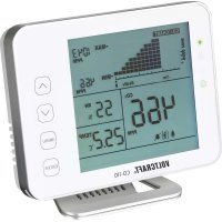
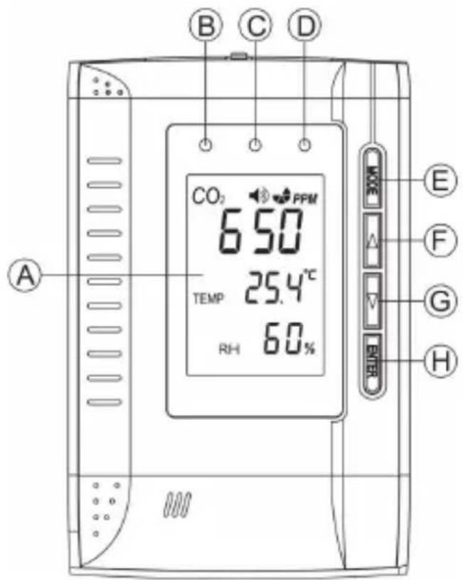
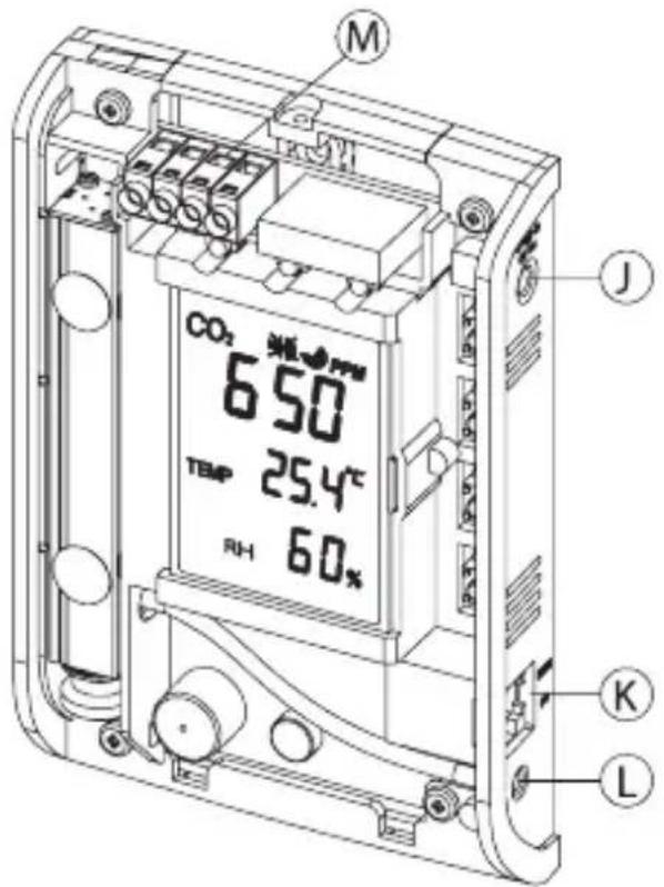
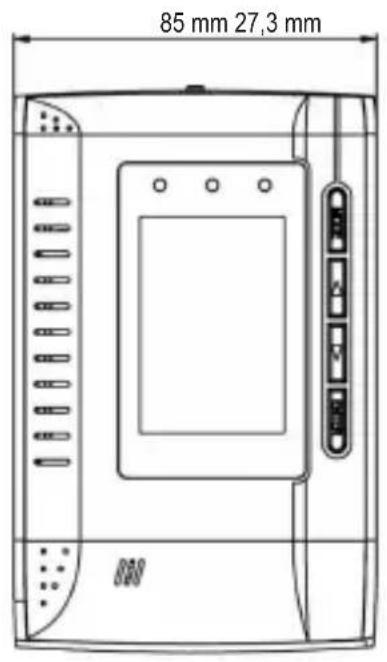
6. CONTROLS ELEMENTS
text_image
B C D CO₂ PPM 650 TEMP 25.4°C RH 60% A E F G H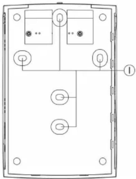
natural_image
Technical line drawing of a device rear panel with internal components and mounting holes (no text or symbols)A LC display
B Green LED
C Yellow LED
D Red LED
E „MODE“ button
F " ▲" button
G "▼" button
H „ENTER“ button
I Holes for wall-mounting
J Low-voltage socket/power supply
K RJ45 socket (for the manufacturer only)
L Gas measurement aperture
M Terminal block for power supply and relay output
text_image
M CO₂ 650 TEMP 25.4°C RH 60% J K L7. WALL INSTALLATION AND CONNECTION
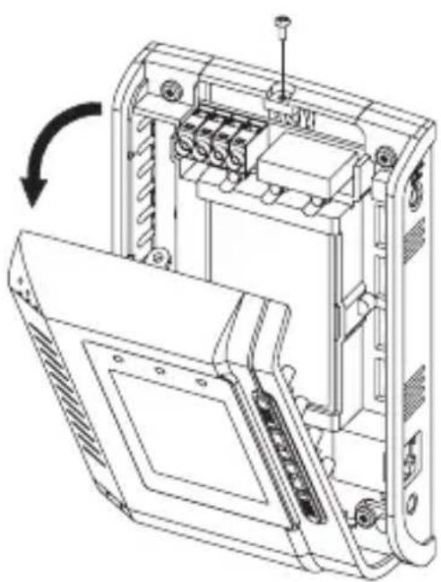
To operate the CO_2 meter stationarily it can be mounted, e.g. on a wall, using the corresponding holes on its rear.
Observe that the gas measurement aperture (see chapter 6, item „L“) is free and not blocked.
A mains socket also needs to be present in proximity of the CO_2 meter.
Proceed as follows:
- Disconnect the CO2 meter from the mains voltage.
Disconnect the low-voltage plug of the mains adapter from the corresponding socket of the CO2 meter. - Loosen the single screw at the top of the casing and then carefully fold down the front until it can be removed.
- Remove the bottom plate. Four screws must be removed for this.
- Now the bottom plate can be mounted on the wall with the holes in it.
Ensure that no cables or lines are damaged when drilling and screwing.
Also observe that the screws do not protrude too far and damage the PCB. Use only flat-headed screws.
- Insert the PCB again and screw it on.
natural_image
Technical line drawing of an electronic device internal structure with no visible text or symbols
natural_image
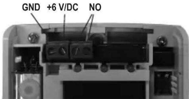
Technical line drawing of a device rear panel assembly with mounting holes and internal components (no text or symbols)- A relay output is available at the terminal strip (see chapter 6, item „M“). The relay is activated when the upper threshold 2 (see chapter 9 c) is exceeded (red LED lights up). The relay therefore works as a NO contact (NO = „normally open“ = closer contact).
The two other terminals can be used for power supply if you do not wish to connect the included mains adapter.
→ Only a stabilised direct voltage of 6 V/DC must be used, and a minimum current of 300 mA must be available (terminal „GND“ for minus/-, terminal „6 V/DC“ for plus/+).
text_image
GND +6 V/DC NO→ See the bottom of the PCB for terminal contact labels.
The bottom plate has the apertures for installing the connection cables.
• To close the casing, first attach the front to the bottom plate at the bottom.
Carefully fold up the front and fasten it with the screw removed initially.
- Connect the CO_2 meter to the mains voltage.
Attention!
The RJ45 connection (see chapter 7, item „K“) must not be used. The connection is only intended for the manufacturer.
8. START-UP
- To take the CO2 meter into operation, connect the round plug of the included mains adapter to the low-voltage socket at the side of the CO2 meter, and plug it in a mains socket.
→ If you have used the internal screw terminals for power supply, the mains adapter must not be connected. - For a brief moment, all display segments will appear and the CO_2 meter emits a signal sound. Then the display shows "WARM UP".
- The CO_2 meter now needs approx. 1 minute for warm-up. During this time, all buttons are deactivated.
In this time, the first CO_2 concentration measurement is performed. The display also indicates humidity and temperature.
Wait until warming up is completed and the „WARM UM“ display disappears.
- The CO_2 meter is now ready for operation.
→ If the CO_2 meter measures a CO_2 concentration exceeding 1200ppm after warm-up (e.g. in an office room), the red LED lights up.
A signal sound may also be emitted (depending on factory settings) to indicate that the upper threshold value was exceeded. To activate signal sound muting, see chapter 10. a).
The yellow LED lights up at a CO_2 concentration between 800 and 1200ppm.
To programme new threshold values for the CO_2 measurement, proceed as described in chapters 9 b) and 9 c).
Also set the correct altitude at the installation site (barometric pressure compensation, see chapter 9 d).
a) Muting the Signal Sound
When the upper CO_2 threshold is exceeded („ALARM2“, see chapter 9 c), factory settings 1200ppm), a loud signal sound is emitted in addition to the red LED lighting up.
This signal sound can be muted, e.g. to switch it off during programming.
Proceed as follows:
- Briefly press the „MODE“ button repeatedly (from the normal operating mode) until „MUTE“ flashes on the display.
- Briefly press the button „ENTER“; the medium display line shows „ON“ or „OFF“.
„ON“ = muting active, signal sound off
„OFF“ = muting not active, signal sound on
- Select between „ON“ and „OFF“ using the arrow buttons „▲“ or „▼“.
- Briefly press the button „ENTER“ to save the setting.
- The signal sound settings are now displayed at the top:

= muting active, signal sound off

= muting not active, signal sound on
b) Setting Threshold Value 1
If the measured CO_2 concentration is below threshold value 1 (factory settings 800ppm), the green LED is lit. When the CO_2 concentration set as threshold value 1 is exceeded, the green LED goes out and the yellow LED lights up.
Set threshold value 1 as follows:
- Briefly press the „MODE“ button repeatedly (from the normal operating mode) until „ALARM 1“ flashes on the display.
- Briefly press the button „ENTER“; the medium display line shows the display for threshold value 1.
- Set threshold value 1 with the arrows „▲“ and „▼“. Below 1000ppm, the step width is 50ppm, above 1000ppm it is 100ppm.
- Briefly press the „ENTER“ button to save the setting.
→ Threshold value 1 always needs to be set lower than threshold value 2!
c) Setting Threshold Value 2
If the measured CO_2 concentration is below threshold value 2 (factory settings 1200ppm), the green LED is lit. When the CO_2 concentration set as threshold value 2 is exceeded, the yellow LED goes out and the red LED lights up. A signal sound can also be emitted (for muting the sound signal, see chapter 9 a).
Set threshold value 2 as follows:
- Briefly press the „MODE“ button repeatedly (from the normal operating mode) until „ALARM 2“ flashes on the display.
- Briefly press the button „ENTER“; the medium display line shows the display for threshold value 2.
- Set threshold value 2 with the arrows „▲“ and „▼“. Below 1000ppm, the step width is 50ppm, above 1000ppm it is 100ppm.
- Briefly press the button „ENTER“ to save the setting.
→ Threshold value 2 always needs to be set higher than threshold value 1!
d) Setting Altitude (Altitude Compensation)
To receive correct values from your measurements, the altitude at the operating site of the CO_2 meter must be set. The setting uses altitude meters referring to sea level (NN = sea level).
Proceed as follows:
- Briefly press the „MODE“ button repeatedly (from the normal operating mode) until „ALTI“ flashes on the display.
- Briefly press the button „ENTER“; the medium display line shows the altitude display and the altitude unit „m“ (meter) flashes.
- Set the altitude with the arrows „▲“ and „▼“.
- Briefly press the button „ENTER“ to save the setting.
e) Setting the Carbon Dioxide Normal Value in the Outside Area
The carbon dioxide normal value is required as a reference value to calculate the ventilation rate („VENT RATE“) (also see chapter 9 i). The pre-set reference value is the generally applicable value of 400ppm (average value of CO_2 concentration in the atmosphere).
To change the normal value, proceed as follows:
- Briefly press the „MODE“ button repeatedly (from the normal operating mode) until „OUTSIDE“ flashes on the display.
- Briefly press the button „ENTER“; the medium display line shows the reference value (factory setting 400ppm).
- Set the reference value with the arrows „▲“ and „▼“.
- Briefly press the button „ENTER“ to save the setting.
f) Calibration
Calibration was already performed by the manufacturer. nevertheless, you can perform calibration again yourself.
→ Observe that new calibration only makes sense if a more precise value for calibration is known to you!
- You have another, precisely calibrated CO_2 meter. Of course, you can perform calibration yourself then.
- You are using the value of the average CO2 concentration present in the atmosphere outside, e.g. outside a building. However, strong deviations may occur depending on environmental conditions (town, road, forest; industrial area, exhaust, etc.)! Usually, the outside CO2 concentration is at 380-420ppm.
Attention! The product will be damaged if it becomes damp or wet. The mains adapter also poses fatal danger from electric shock!
- Let CO_2 gas at a known concentration escape close to the gas measurement opening. Air currents and environmental conditions may, however, also cause strong deviations here.
We therefore recommend leaving the manufacturer's calibration or only performing calibration using another, precisely calibrated CO2 meter or if you know the precise CO2 concentration.
Start calibration as follows:
- Briefly press the „MODE“ button repeatedly (from the normal operating mode) until „CALI“ flashes on the display.
- Briefly press the button „ENTER“; the medium display line shows the calibration value display.
- Set the calibration value with the arrows „▲“ and „▼“. The calibration value is the CO₂ measured value you want to use for calibration, see above.
- Keep the „MODE“ button pressed for approx. 10 seconds. The display „CALIBRATING“ flashes at the bottom of the display. Calibration tapes approx. 3 minutes.

Important: Never breathe next to the CO_2 meter. Keep sufficient distance. Avoid strong airstreams, do not move the CO_2 meter.
- After completion of calibration, the display indicates „PASS“ (calibration successful) or „FAIL“ (calibration unsuccessful).
→ Defective calibration can occur in particular if the CO_2 concentration fluctuates during calibration.
Eliminate any interfering influences and perform calibration again.
- Briefly press „ENTER“ to leave calibration mode. The CO _2 meter returns to normal display.
g) Datalogger Function (Data Memory)
The CO_2 meter automatically stores the measured CO_2 (carbon dioxide), temperature and humidity values for the last 24 hours at 30-minute intervals.
The oldest dataset is overwritten each time. All in all, a maximum of 48 datasets can be stored.
→ The data remains stored even if the CO_2 meter is disconnected from the power supply.
Proceed as follows to display the data:
- Briefly press the „MODE“ button repeatedly (from the normal operating mode) until „DATALOGGER“ flashes on the display.
- Briefly press the button „ENTER“; the last dataset is displayed. The top display line alternates between CO₂ concentration and dataset number.
Latest dataset = # 1 (30 minutes ago)
Oldest dataset = #48 (24 hours ago)
- Select a dataset with the arrows „▲“ and „▼“.
- Briefly press „ENTER“ to leave dataset display. The CO _2 meter returns to normal display.
h) Displaying/Resetting MAX/MIN Values
In operation, the CO_2 meter stores the highest and lowest CO_2 value measured. This enables, e.g., quick determination of peak loads.
This maximum and minimum memory can, of course, be reset.
Proceed as follows:
- Briefly press the „MODE“ button repeatedly (from the normal operating mode) until „MAX MIN“ flashes on the display.
- Briefly press the „ENTER“ button. The display now alternates between maximum and minimum CO₂ concentration values and the corresponding temperature / humidity.
- If the maximum and minimum value is to be reset, briefly press one of the arrows „▲“ and „▼“, so that „CLR“ appears on the display (press the arrow again to leave deletion mode again).
Briefly press the „ENTER“ button while „CLR“ is displayed to reset the maximum and minimum values to the current measured value. The CO_2 meter returns to normal display.
→ The current measured value is displayed as the new maximum and minimum value until another change happens.
- If the values are not to be reset, briefly press one of the errors. „CLR“ disappears. Then briefly press the „ENTER“ button. The CO₂ meter returns to normal display.
i) Resetting the CO₂ Meter to Factory Settings
This function resets the CO_2 meter to factory settings.
→ Not only the threshold value settings, but also basic calibration is reset.
All 48 data memory slots (see chapter 9 g) are also deleted.
Proceed as follows:
- Briefly press the „MODE“ button repeatedly (from the normal operating mode) until „RcFS“ flashes on the display („RcFS“ = Recover the Factory Settings“).
- Briefly press the button „ENTER“; the top display line shows „NO“.
- Select between „NO“ and „YES“ using the arrow buttons „▲“ or „▼“.
„NO“ = do not reset
„YES“ = Reset to default settings
- Briefly press the „ENTER“ button.
If you selected „NO“, the CO_2 meter returns to normal display without resetting factory settings.
Selecting „YES“ resets all settings to factory settings and deletes all 48 data memory slots. Then the CO_2 meter returns to normal display.
j) Displaying Temperature/Ventilation Rate
The medium display line can be switched between temperature and ventilation rate display.
The ventilation rate indicates how much air is recirculated from outside to the inside. This is calculated from the change of the CO_2 concentration within a certain period and the difference to the CO_2 concentration outside (atmosphere, approx. 400ppm). A low value corresponds to a bad ventilation rate (low air exchange), a high value to a good ventilation rate (large air exchange).
→ A good ventilation rate may also point to waste of energy, e.g. due to windows not being tight.
For an indicative value, read the values only after 2-3 hours, once the CO_2 concentration has stabilised, e.g. after all employees have left the office.
Proceed as follows:
Repeatedly press the arrow „▲“ or „▼“ in normal operating mode; the middle display line switches between the following displays:
• Measured temperature value
- Ventilation rate l/p/s (litres of air per second and person)
- Ventilation rate m^3/p/s (cubic metres of air per second and person)
10. MAINTENANCE AND CARE
The product is maintenance-free for you. Never take it apart (except for mounting as described in these operating instructions).
Repair or maintenance work must be carried out by a specialist.
Use a soft, dry and clean cloth only for cleaning.
Do not press too hard on the display. This may cause scratches and damage the display.
Dust can be removed very easily using a soft, clean brush and vacuum cleaner.
Never use any aggressive cleaning agents or chemical solutions that may damage the surface of the casing.
11. DISPOSAL
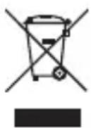
At the end of its service life, dispose of the product according to the relevant statutory regulations.
12. TECHNICAL DATA
a) CO_2 Meter
General:
Operating voltage 6 V/DC
Ambient temperature 0 °C to +50 °C
Ambient air humidity .... 0% to 95% rel. humidity, non-condensing
Relay load capacity .... max. 30 V/DC, 2 A
Weight 180 g
Dimensions ...... see figures
text_image
85 mm 27,3 mm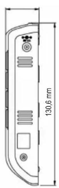
text_image
130,6 mm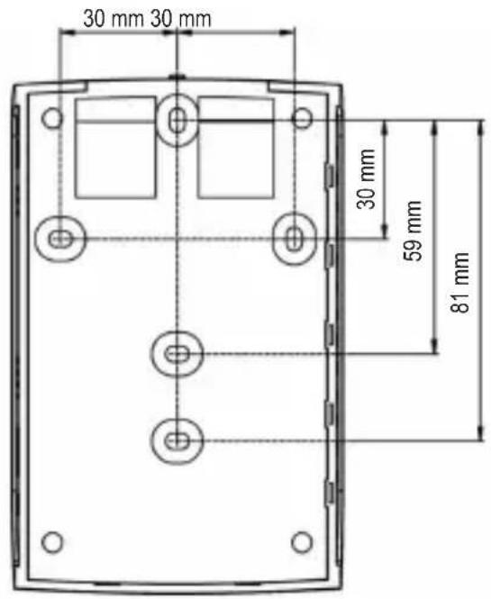
text_image
30 mm 30 mm 30 mm 59 mm 81 mmCO_2 sensor:
Measuring range 0 - 3000ppm
Resolution 1ppm at 0 - 1000ppm
5ppm at 1001 - 2000ppm
10ppm at 2001 - 3000ppm
Accuracy ....±75ppm (or ±5%) at 0 - 2000ppm
±7% at >2000ppm
(Data applies for a period of 5 years)
Reproducibility .... ±20ppm at 400ppm
Temperature influence ....±2ppm or 0.2% of the reading per °C
Barometric pressure influence .... 0.13% of the reading
(Correction by altitude entry possible)
Warm-up time .... <60 seconds
Temperature sensor:
Measuring range 0 °C to +50 °C
Resolution 0.1 °C
Accuracy .... ±1 °C (in direct airflow ±1.5 °C)
Humidity sensor:
Measuring range 20% to 90% rel. humidity
Resolution 1% relative humidity
Accuracy .... ±5% relative humidity at +23 °C
b) Mains Adapter
Operating voltage 100 - 240 V/AC, 50/60 Hz
Output 6 V/DC, 0.3 A
Page
text_image
B C D CO₂ PPM 650 TEMP 25.4°C RH 60% A E F G H
natural_image
Technical line drawing of a device rear panel with internal components and mounting holes (no text or symbols)A Écran LCD
B DEL verte
C DEL jaune
D DEL rouge
E Touche « MODE »
F Touche « ▲ »
G Touche « ▼ »
H Touche « ENTER »
text_image
M CO₂ 650 PPM TEMP 25.4°C RH 60% J K L7. MONTAGE MURAL ET RACCORDEMENT
natural_image
Technical line drawing of an open computer case with internal components and a scroll arrow indicating rotation (no text or symbols present)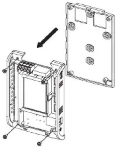
natural_image
Technical line drawing of a device housing assembly showing internal components and mounting points (no text or symbols)text_image
B C D CO₂ PPM 650 TEMP 25.4°C RH 60% A E F G H
natural_image
Technical line drawing of a device rear panel with internal components and mounting holes (no text or symbols)A LC-display
B Groene LED
C Gele LED
D Rode LED
E Toets "MODE"
F Toets "▲"
G Toets "▼"
H Toets "ENTER"
text_image
M CO₂ 650 TEMP 25.4°C RH 60% J K L7. WANDMONTAGE EN AANSLUITING
natural_image
Technical line drawing of an open computer case with internal components and a scroll arrow indicating rotation (no text or symbols present)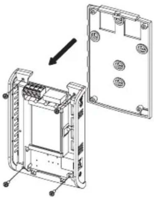
natural_image
Technical line drawing of a device housing assembly showing internal components and mounting holes (no text or symbols)© Copyright 2013 by Voltcraft®.

Legal Notice
These operating instructions are a publication by Voltcraft®, Lindenweg 15, D-92242 Hirschau/Germany, Phone +49 180/586 582 7 (www.voltcraft.de).
All rights including translation reserved. Reproduction by any method, e.g. photocopy, microfilming, or the capture in electronic data processing systems require the prior written approval by the editor. Reprinting, also in part, is prohibited.
These operating instructions represent the technical status at the time of printing. Changes in technology and equipment reserved.
© Copyright 2013 by Voltcraft®.

Information légales
© Copyright 2013 by Voltcraft®. V2_0213_01