
PSW 250-9 - Uncategorized VOLTCRAFT - Free user manual and instructions
Find the device manual for free PSW 250-9 VOLTCRAFT in PDF.


| Product Type | Multi-Range DC Power Supply |
| Brand | VOLTCRAFT |
| Model | PSW 250-9 |
| Output Voltage | 0 ~ 250 V |
| Output Current | 0 ~ 9 A |
| Rated Power | 720 W |
| Input Voltage | 85 VAC ~ 265 VAC |
| Input Frequency | 47 Hz ~ 63 Hz |
| Efficiency | Up to 82% (at 200 VAC) |
| Dimensions (W x H x D) | 142 mm x 124 mm x 350 mm |
| Weight | Approx. 5.3 kg |
| Cooling | Forced air cooling by internal fan |
| Operating Temperature | 0 °C to 50 °C |
| Storage Temperature | -25 °C to 70 °C |
| Relative Humidity (Operating) | 20% to 85% (non-condensing) |
| Protection Features | OVP, OCP, OTP, Power Limit |
| Interfaces | USB (Host/Device), LAN, Analog Control Connector |
| Remote Sense Compensation | Up to 1 V per wire |
| Internal Resistance Setting Range | 0.00 Ω ~ 27.77 Ω |
| Bleeder Control | Switchable (default ON) |
| Parallel Capability | Up to 3 units (same model) |
| Series Capability | Not supported for 250V models |
| Safety Compliance | CE, EN 61010-1, EN 61010-2-030 |
| Standards Included | Power cord, USB cable, output terminal cover, basic accessory kit |
Frequently Asked Questions - PSW 250-9 VOLTCRAFT
User questions about PSW 250-9 VOLTCRAFT
0 question about this device. Answer the ones you know or ask your own.
Ask a new question about this device
Download the instructions for your Uncategorized in PDF format for free! Find your manual PSW 250-9 - VOLTCRAFT and take your electronic device back in hand. On this page are published all the documents necessary for the use of your device. PSW 250-9 by VOLTCRAFT.
USER MANUAL PSW 250-9 VOLTCRAFT
Multi-Range DC Power Supply
PSW Series
USER MANUAL
GW INSTEK PART NO. 82SW-80400MI1
This manual contains proprietary information, which is protected by copyright. All rights are reserved. No part of this manual may be photocopied, reproduced or translated to another language without prior written consent of Good Will company.
The information in this manual was correct at the time of printing. However, Good Will continues to improve products and reserves the rights to change specification, equipment, and maintenance procedures at any time without notice.
Table of Contents
SAFETY INSTRUCTIONS 5
GETTING STARTED 9
PSW Series Overview 10
Appearance....15
Theory of Operation....22
OPERATION.... 35
Set Up....37
Basic Operation 57
Parallel / Series Operation....72
Test Scripts 87
CONFIGURATION 96
Configuration....97
ANALOG CONTROL....116
Analog Remote Control Overview...... 117
Remote Monitoring.... 133
COMMUNICATION INTERFACE....138
Interface Configuration 139
MAINTENANCE ....154
FAQ 156
APPENDIX 158
PSW Default Settings.... 158
Error Messages & Messages ...... 161
LED Display Format 161
PSW Specifications 162
PSW Dimensions 177
Declaration of Conformity 182
INDEX....183
SAFETY INSTRUCTIONS
This chapter contains important safety instructions that you must follow during operation and storage. Read the following before any operation to insure your safety and to keep the instrument in the best possible condition.
Safety Symbols
These safety symbols may appear in this manual or on the instrument.

WARNING
Warning: Identifies conditions or practices that could result in injury or loss of life.

CAUTION
Caution: Identifies conditions or practices that could result in damage to the PSW or to other properties.

DANGER High Voltage

Attention Refer to the Manual

Protective Conductor Terminal

Earth (ground) Terminal
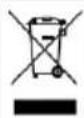
Do not dispose electronic equipment as unsorted municipal waste. Please use a separate collection facility or contact the supplier from which this instrument was purchased.
Safety Guidelines
General Guideline

CAUTION
- Do not place any heavy object on the PSW.
- Avoid severe impact or rough handling that leads to damaging the PSW.
- Do not discharge static electricity to the PSW.
- Use only mating connectors, not bare wires, for the terminals.
- Do not block the cooling fan opening.
- Do not disassemble the PSW unless you are qualified.
(Measurement categories) EN 61010-1:2010 and EN 61010-2-030 specify the measurement categories and their requirements as follows. The PSW falls under category II.
- Measurement category IV is for measurement performed at the source of low-voltage installation.
- Measurement category III is for measurement performed in the building installation.
- Measurement category II is for measurement performed on the circuits directly connected to the low voltage installation.
- 0 is for measurements performed on circuits not directly connected to Mains.
Power Supply

WARNING
- AC Input voltage range: 85VAC\~265VAC
• Frequency: 47Hz\~63Hz - To avoid electrical shock connect the protective grounding conductor of the AC power cord to an earth ground.
| Cleaning the PSW | Disconnect the power cord before cleaning.Use a soft cloth dampened in a solution of mild detergent and water. Do not spray any liquid.Do not use chemicals containing harsh material such as benzene, toluene, xylene, and acetone. |
| Operation Environment | Location: Indoor, no direct sunlight, dust free, almost non-conductive pollution (Note below)Relative Humidity: 20%~85%Altitude: <2000mTemperature: 0°C to 50°C(Pollution Degree) EN 61010-1:2010 and EN 61010-2-030 specify the pollution degrees and their requirements as follows. The PSW falls under degree 2.Pollution refers to “addition of foreign matter, solid, liquid, or gaseous (ionized gases), that may produce a reduction of dielectric strength or surface resistivity”.Pollution degree 1: No pollution or only dry, non-conductive pollution occurs. The pollution has no influence.Pollution degree 2: Normally only non-conductive pollution occurs. Occasionally, however, a temporary conductivity caused by condensation must be expected.Pollution degree 3: Conductive pollution occurs, or dry, non-conductive pollution occurs which becomes conductive due to condensation which is expected. In such conditions, equipment is normally protected against exposure to direct sunlight, precipitation, and full wind pressure, but neither temperature nor humidity is controlled. |
| Storage environment | Location: IndoorTemperature: -25°C to 70°CRelative Humidity: <90%, no condensation |
Disposal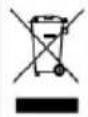 | Do not dispose this instrument as unsorted municipal waste. Please use a separate collection facility or contact the supplier from which this instrument was purchased. Please make sure discarded electrical waste is properly recycled to reduce environmental impact. |
Power cord for the United Kingdom
When using the power supply in the United Kingdom, make sure the power cord meets the following safety instructions.
NOTE: This lead/appliance must only be wired by competent persons

WARNING: THIS APPLIANCE MUST BE EARTHED
IMPORTANT: The wires in this lead are coloured in accordance with the following code:
Green/ Yellow:
Earth
Blue:
Neutral
Brown:
Live (Phase)
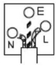
As the colours of the wires in main leads may not correspond with the coloured marking identified in your plug/appliance, proceed as follows:
The wire which is coloured Green & Yellow must be connected to the Earth terminal marked with either the letter E, the earth symbol or coloured Green/Green & Yellow.
The wire which is coloured Blue must be connected to the terminal which is marked with the letter N or coloured Blue or Black.
The wire which is coloured Brown must be connected to the terminal marked with the letter L or P or coloured Brown or Red.
If in doubt, consult the instructions provided with the equipment or contact the supplier.
This cable/appliance should be protected by a suitably rated and approved HBC mains fuse: refer to the rating information on the equipment and/or user instructions for details. As a guide, a cable of 0.75mm^2 should be protected by a 3A or 5A fuse. Larger conductors would normally require 13A types, depending on the connection method used.
Any exposed wiring from a cable, plug or connection that is engaged in a live socket is extremely hazardous. If a cable or plug is deemed hazardous, turn off the mains power and remove the cable, any fuses and fuse assemblies. All hazardous wiring must be immediately destroyed and replaced in accordance to the above standard.
GETTING STARTED
This chapter describes the power supply in a nutshell, including its main features and front / rear panel introduction. After going through the overview, please read the theory of operation to become familiar with the operating modes, protection modes and other safety considerations.
natural_image
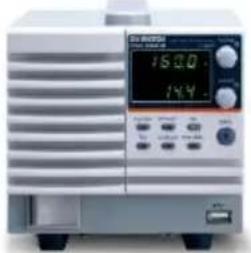
Front view of a silver electronic device with a digital display and control buttons (no visible text or symbols)PSW Series Overview.... 10
Series lineup....10
Main Features....11
Accessories....12
PSW 30/80/160 Accessories....12
PSW 250/800 Accessories....13
Appearance 15
PSW Front Panel 15
Rear Panel....18
PSW Series Overview
Series lineup
The PSW series consists of 15 models, divided into 3 different model types covering 3 power capacities: Type I (360 Watt), Type II (720 Watt) and Type III (1080 Watt).

Note
Throughout the user manual, PSW 30, PSW 80, PSW 160, PSW 250 or PSW 800 will refer to any of the PSW models with a maximum voltage rating of 30V, 80V, 160V, 250V or 800V, respectively.
| Model name | Type | Voltage Rating | Current Rating | Power |
| PSW 30-36 | Type I | 0~30V | 0~36A | 360W |
| PSW 80-13.5 | Type I | 0~80V | 0~13.5A | 360W |
| PSW 160-7.2 | Type I | 0~160V | 0~7.2A | 360W |
| PSW 250-4.5 | Type I | 0~250V | 0~4.5A | 360W |
| PSW 800-1.44 | Type I | 0~800V | 0~1.44A | 360W |
| PSW 30-72 | Type II | 0~30V | 0~72A | 720W |
| PSW 80-27 | Type II | 0~80V | 0~27A | 720W |
| PSW 160-14.4 | Type II | 0~160V | 0~14.4A | 720W |
| PSW 250-9 | Type II | 0~250V | 0~9A | 720W |
| PSW 800-2.88 | Type II | 0~800V | 0~2.88A | 720W |
| PSW 30-108 | Type III | 0~30V | 0~108A | 1080W |
| PSW 80-40.5 | Type III | 0~80V | 0~40.5A | 1080W |
| PSW 160-21.6 | Type III | 0~160V | 0~21.6A | 1080W |
| PSW 250-13.5 | Type III | 0~250V | 0~13.5A | 1080W |
| PSW 800-4.32 | Type III | 0~800V | 0~4.32A | 1080W |
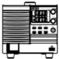
Apart from the differences in output, each unit differs in size. The 720 and 1080 watt models are larger than the 360 watt models to accommodate the increase in power.
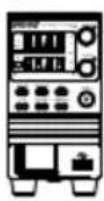
360 Watt models
720 Watt models
1080 Watt models
Type I
Type II
Type III
natural_image
Line drawing of a portable electronic device with control panel and buttons (no text or symbols)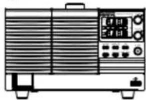
natural_image
Line drawing of a portable electronic device with ventilation grilles and control panel (no text or symbols)Main Features
Performance
• High performance/power
• Power efficient switching type power supply
• Low impact on load devices
• Fast transient recovery time of 1ms
• Fast output response time
Interface
- Ethernet port
- Analog connector for analog voltage and current monitoring
- USB host and device port
Accessories
Please check the contents before using the PSW.
PSW 30/80/160 Accessories
| Standard Accessories | Part number | Description |
| CD-ROM | User manual, programming manual | |
| 4323-30600101 | Power cord (Type I/II) | |
| 4320-91001101 | Power cord (Type III) | |
| 1042-SWLV0301 | Output terminal cover | |
| GTL-123 | Test leads: 1x red, 1x black | |
| GTL-240 | USB Cable | |
| PSW-004 | Basic Accessory Kit: M4 terminal screws and washers x2, M8 terminal bolts, nuts and washers x2, Air filter x1, Analog control protection dummy x1, Analog control lock level x1 | |
| Optional Accessories | Part number | Description |
| GET-001 | Extended terminal | |
| PSW-001 | Accessory Kit: Pin contact x10, Socket x1, Protection cover x1 | |
| PSW-002 | Simple IDC Tool 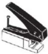 | |
| PSW-003 | Contact Removal Tool 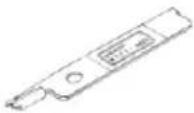 | |
| PSW-005 | Series operation cable for 2 units. | |
| PSW-006 | Parallel operation cable for 2 units. | |
| PSW-007 | Parallel operation cable for 3 units. | |
| GRA-410-J | Rack mount adapter (JIS) | |
| GRA-410-E | Rack mount adapter (EIA) | |
| GUG-001 | GPIB to USB adapter | |
| GTL-240 | USB Cable | |
| 57RG-30B00201 | Large filter (Type II/III) | |
| Download | Name | Description |
| psw_cdc.inf | USB driver |
PSW 250/800 Accessories
| Standard Accessories | Part number | Description |
| CD-ROM | User manual, programming manual | |
| 4323-30600101 | Power cord (Type I/II) | |
| 4320-91001101 | Power cord (Type III) | |
| 1042-SWHV0301 | High voltage output terminal cover | |
| GTL-240 | USB Cable | |
| 39BT-50900401 | High voltage output terminal | |
| PSW-008 | Basic Accessory Kit:(Air filter x1, Analog control protection dummy x1, Analog control lock level x1 | |
| Optional Accessories | Part number | Description |
| GET-002 | Extended terminal | |
| PSW-001 | Accessory Kit:Pin contact x10, Socket x1, Protection cover x1 | |
| PSW-002 | Simple IDCTool 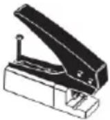 | |
| PSW-003 | ContactRemoval Tool 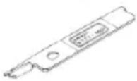 | |
| PSW-006 | Parallel operation cable for 2 units. | |
| PSW-007 | Parallel operation cable for 3 units. | |
| GRA-410-J | Rack mount adapter (JIS) | |
| GRA-410-E | Rack mount adapter (EIA) | |
| GTL-130 | Test leads: 2x red, 2x black | |
| GUG-001 | GPIB to USB adapter | |
| GTL-240 | USB Cable | |
| 57RG-30B00201 | Large filter (Type II/III) | |
| Download | Name | Description |
| psw_cdc.inf | USB driver |
Appearance
PSW Front Panel
720W: PSW 30-72, 80-27, 160-14.4, 250-9, 800-2.88
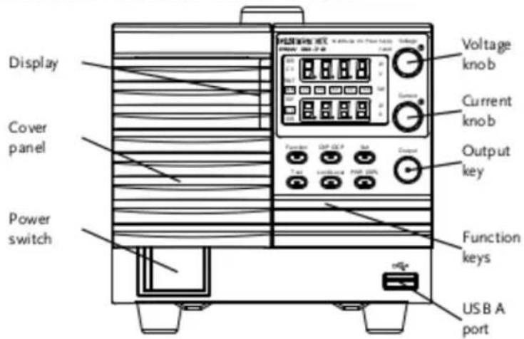
Function Keys
The Function keys along with the Output key will light up when a key is active.
The Function key is used to configure the power supply.
Set the over current or over voltage protection levels.
Sets the current and voltage limits.
Used to run customized scripts for testing.
Locks or unlocks the panel keys to prevent accidentally changing panel settings.
Toggles the display from viewing V/A → V/W or A/W ^ . ^ Press the Voltage knob for V/W, press the Current knob for A/W.
Display Indicators
VSR
Voltage Slew Rate
CV
Constant Voltage Mode
RMT
Remote Control Mode
ALM
Alarm on
DLY
Delay Output
C C
Constant Current Mode
ISR
Current Slew Rate
| 20 | 40 | 60 |
| 80 | 100 | % W |
Power bar
Indicates the current power output as a percentage.
Voltage Knob
Sets the voltage.
Current Knob
Sets the current.
Output
Press to turn on the output. The Output key will light up when the output is active.
USB
USB A port for data transfer, loading test scripts etc.
Power Switch
natural_image
Simple diagram with a circle inside a rectangle and an 'I' symbol inside, no text or labels present.Used to turn the power on/off.
Rear Panel
720W: PSW 30-72, 80-27, 160-14.4
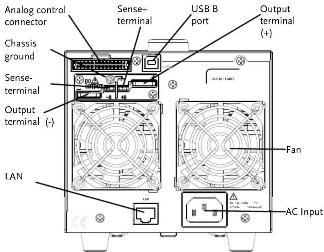
1080W: PSW 30-108, 80-40.5, 160-21.6
360W: PSW 30-36, 80-13.5, 160-7.2
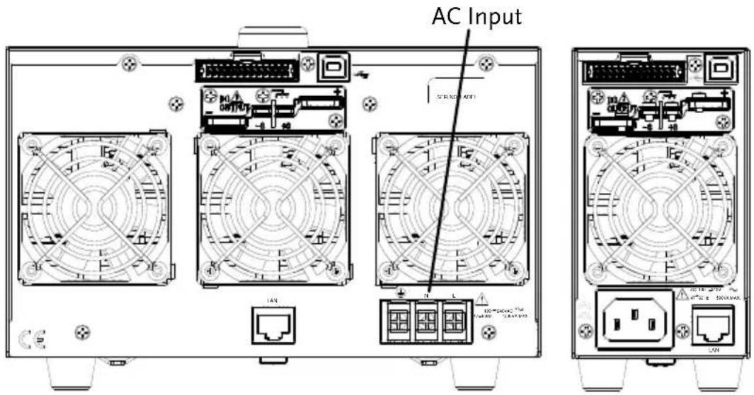
720W: PSW 250-9, 800-2.88
1080W: PSW 250-13.5, 800-4.32
360W: PSW 250-4.5, 800-1.44
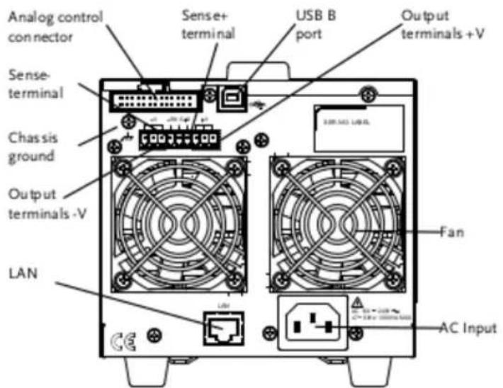
AC Input
Analog Control Connector
Standard 26 pin MIL connector (OMRON XG4 IDC plug).
The analog control connector is used to monitor current and voltage output, machine status (OVP, OCP, OTP etc.), and for analog control of the current and voltage output.
Use an OMRON XG5 IDC socket as the mating socket.
Output Terminals (30, 80, 160 volt models)
Positive (+) and negative (-) output terminals.
Chassis ground
Sense (-S) and Sense (+S) terminals.
Output Terminals The 250 and 800 volt models use a 9 pin connector
USB B port
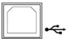
The USB B port is used for remote control.
Fans
Temperature controlled fans
Ethernet Port
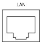
The ethernet port is used for remote control and digital monitoring from a PC.
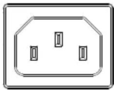
Line Voltage Input (Type I/TypeII)
natural_image
Simple line drawing of an octagonal socket with three internal slots (no text or symbols)Type I: PSW 30-36/80-13.5/160-7.2/250-4.5, 800-1.44
Type II: PSW 30-72/80-27/160-14.4/250-9, 800-2.88
• Voltage Input: 100\~240 VAC
• Line frequency: 50Hz/60 Hz (Automatically switchable)
Line Voltage Input (Type III)
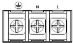
Type III: PSW 30-108/80-40.5/160-21.6/ 250-13.5/800-4.32
• Voltage Input: 100\~240 VAC
• Line frequency: 50Hz/60 Hz (Automatically switchable)
Theory of Operation
The theory of operation chapter describes the basic principles of operation, protection modes and important considerations that must be taken into account before use.
Operating Area Description
Background
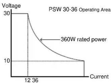
The PSW power supplies are regulated DC power supplies with a high voltage and current output. These operate in CC or CV mode within a wide operating range limited only by the output power.
The operating area of each power supply is determined by the rated output power as well as the voltage and current rating. For example the operating area and rated power output for the PSW 30-36 is shown below.
line
| Current | Voltage | | ------- | ------- | | 12 | 30 | | 36 | 10 |When the power supply is configured so that the total output (current x voltage output) is less than the rated power output, the power supply functions as a typical constant current, constant voltage power supply.
If however, the power supply is configured such that the total output (current x voltage output) exceeds the rated power output, the
effective output is actually limited to the power limit of the unit. In this case the output current and voltage then depend purely on the load value.
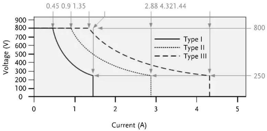
Below is a comparison of the operating areas of each power supply.
PSW 800V Series Operating Area
line
| Current (A) | Voltage (V) - Type I | Voltage (V) - Type II | Voltage (V) - Type III | |-------------|----------------------|-----------------------|------------------------| | 0.45 | 800 | 800 | 800 | | 0.9 | 700 | 750 | 800 | | 1.35 | 600 | 700 | 800 | | 2.88 | 300 | 250 | 350 | | 4.321 | 250 | 250 | 250 |PSW 250V Series Operating Area
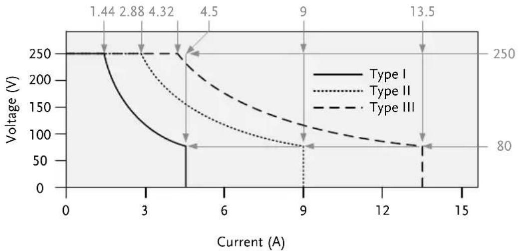
line
| Current (A) | Voltage (V) - Type I | Voltage (V) - Type II | Voltage (V) - Type III | |-------------|----------------------|-----------------------|------------------------| | 0 | 250 | 250 | 250 | | 3 | 100 | 150 | 250 | | 6 | 75 | 100 | 150 | | 9 | 75 | 75 | 100 | | 12 | 75 | 75 | 75 | | 15 | 75 | 75 | 75 |PSW 160V Series Operating Area
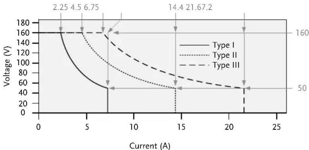
line
| Current (A) | Voltage (V) - Type I | Voltage (V) - Type II | Voltage (V) - Type III | |-------------|----------------------|-----------------------|------------------------| | 2.25 | 160 | 160 | 160 | | 4.5 | 160 | 160 | 160 | | 6.75 | 160 | 160 | 160 | | 14.4 | 50 | 50 | 70 | | 21.67 | 50 | 50 | 50 |PSW 80V Series Operating Area
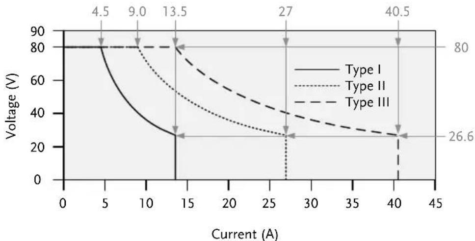
line
| Current (A) | Voltage (V) - Type I | Voltage (V) - Type II | Voltage (V) - Type III | |-------------|----------------------|-----------------------|------------------------| | 0 | 80 | 80 | 80 | | 5 | 80 | 80 | 80 | | 10 | 40 | 60 | 80 | | 15 | 26 | 40 | 80 | | 27 | - | 26.6 | 40 | | 40 | - | - | 26.6 | | 45 | - | - | - |PSW 30V Series Operating Area
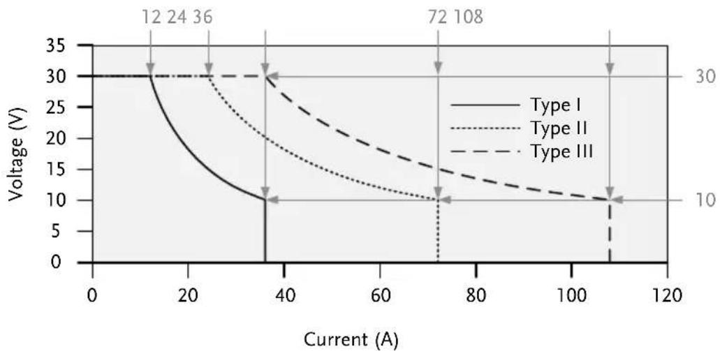
line
| Current (A) | Voltage (V) - Type I | Voltage (V) - Type II | Voltage (V) - Type III | |-------------|----------------------|-----------------------|------------------------| | 12 | 30 | 30 | 30 | | 24 | 25 | 25 | 25 | | 36 | 20 | 20 | 20 | | 72 | 10 | 10 | 10 | | 108 | 10 | 10 | 10 |CC and CV Mode
CC and CV mode Description
When the power supply is operating in constant current mode (CC) a constant current will be supplied to the load. When in constant current mode the voltage output can vary, whilst the current remains constant. When the load resistance increases to the point where the current limit ( I_SET ) can no longer be sustained the power supply switches to CV mode. The point where the power supply switches modes is the crossover point.
When the power supply is operating in CV mode, a constant voltage will be supplied to the load, whilst the current will vary as the load varies. At the point that the load resistance is too low to maintain a constant voltage, the power supply will switch to CC mode and maintain the set current limit.
The conditions that determine whether the power supply operates in CC or CV mode depends on the set current ( I_SET ), the set voltage
(VSET), the load resistance (RL) and the critical resistance (RC). The critical resistance is determined by VSET/ISET. The power supply will operate in CV mode when the load resistance is greater than the critical resistance. This means that the voltage output will be equal to the VSET voltage but the current will be less than ISET. If the load resistance is reduced to the point that the current output reaches the ISET level, the power supply switches to CC mode.
Conversely the power supply will operate in CC mode when the load resistance is less than the critical resistance. In CC mode the current output is equal to I_SET and the voltage output is less than V_SET .
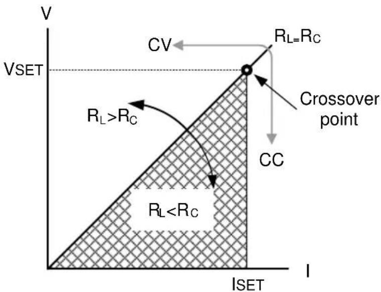
Bleeder Control
Background
The PSW DC power supplies employ a bleed resistor in parallel with the output terminals.  Bleed resistors are designed to dissipate the power from the power supply filter capacitors| when power is turned off and the load is disconnected. Without a bleed resistor, power may remain charged on the filter capacitors for some time and be potentially hazardous.In addition, bleed resistors also allow for smoother voltage regulation of the power supply as the bleed resistor acts as a minimum voltage load.The bleed resistance can be turned on or off using the configuration settings. | |
 Note Note | By default the bleed resistance is on. For battery charging applications, be sure to turn the bleed resistance off as the bleed resistor can discharge the connected battery when the unit is off. |
| Background | On the PSW, the internal resistance of the power supply can be user-defined in software. (Internal Resistance Setting, page 105). When the internal resistance is set it can be seen as a resistance in series with the positive output terminal. This allows the power supply to simulate power sources that have internal resistances such as lead acid batteries. | |
| Internal Resistance Range | Unit Model | Internal Resistance Range |
| PSW 30-36 | 0.000 ~ 0.833Ω | |
| PSW 30-72 | 0.000 ~ 0.417Ω | |
| PSW 30-108 | 0.000 ~ 0.278Ω | |
| PSW 80-13.5 | 0.000 ~ 5.926Ω | |
| PSW 80-27 | 0.000 ~ 2.963Ω | |
| PSW 80-40.5 | 0.000 ~ 1.975Ω | |
| PSW 160-7.2 | 0.000 ~ 22.222Ω | |
| PSW 160-14.4 | 0.000 ~ 11.111Ω | |
| PSW 160-21.6 | 0.000 ~ 7.407Ω | |
| PSW 250-4.5 | 0.00 ~ 55.55Ω |
| PSW 250-9 | 0.00 ~ 27.77Ω |
| PSW 250-13.5 | 0.00 ~ 18.51Ω |
| PSW 800-1.44 | 0.0 ~ 555.5Ω |
| PSW 800-2.88 | 0.0 ~ 277.8Ω |
| PSW 800-4.32 | 0.0 ~ 185.1Ω |
Alarms
The PSW power supplies have a number of protection features. When one of the protection alarms are set, the ALM icon on the display will be lit. For details on how to set the protection modes, please see page 57.| OVP | Overvoltage protection (OVP) prevents a high voltage from damaging the load. |
| OCP | Overcurrent protection prevents high current from damaging the load. |
| OTP | Over temperature protection protects the instrument from overheating. |
| Power Switch Trip | When the Power Switch Trip configuration setting is enabled, the power supply will automatically shut down when a protection setting has been tripped (OCP, OVP, OTP). |
| Alarm output | Alarms are output via the analog control connector. The alarm output is an isolated open-collector photo coupler output. |
Considerations
The following situations should be taken into consideration when using the power supply.| Inrush current | When the power supply switch is first turned on, an inrush current is generated. Ensure there is enough power available for the power supply when first turned on, especially if a number of units are turned on at the same time. |
| Caution | Cycling the power on and off quickly can cause the inrush current limiting circuit to fail as well as reduce the working life of the input fuse and power switch. |
| Pulsed or Peaked loads | When the load has current peaks or is pulsed, it is possible for the maximum current to exceed the mean current value. The PSW power supply ammeter only indicates mean current values, which means for pulsed current loads, the actual current can exceed the indicated value. For pulsed loads, the current limit must be increased, or a power supply with a greater capacity must be chosen. As shown below, a pulsed load may exceed the current limit and the indicated current on the power supply ammeter. |
natural_image
Pure electrical circuit lines without any symbolsGrounding
The output terminals of the PSW power supplies are isolated with respect to the protective grounding terminal. The insulation capacity of the load, the load cables and other connected devices must be taken into consideration when connected to the protective ground or when floating.Floating
As the output terminals are floating, the load and all load cables must have an insulation capacity that is greater than the isolation voltage of the power supply. flowchart
graph LR
    A["Ext-V\nExt-R"] --> B["PSW"]
    B --> C["Load"]
    D["Analog connector"] --> B
    B --> E["Switch"]
    E --> B
WARNING
If the insulation capacity of the load and load cables is not greater than the isolation voltage of the power supply, electric shock may occur. Grounded output terminal If the positive or negative terminal is connected to the protective ground terminal, the insulation capacity needed for the load and load cables is greatly reduced. The insulation capacity only needs to be greater than the maximum output voltage of the power supply with respect to ground. flowchart
graph LR
    A["Ext-V\nExt-R"] --> B["Analog connector"]
    B --> C["PSW"]
    C --> D["Load"]
    C --> E["Measurement Point 1"]
    C --> F["Measurement Point 2"]
    C --> G["Measurement Point 3"]
    C --> H["Measurement Point 4"]
    C --> I["Measurement Point 5"]
    C --> J["Measurement Point 6"]
    C --> K["Measurement Point 7"]
    C --> L["Measurement Point 8"]
    C --> M["Measurement Point 9"]
    C --> N["Measurement Point 10"]
    C --> O["Measurement Point 11"]
    C --> P["Measurement Point 12"]
    C --> Q["Measurement Point 13"]
    C --> R["Measurement Point 14"]
    C --> S["Measurement Point 15"]
    C --> T["Measurement Point 16"]
    C --> U["Measurement Point 17"]
    C --> V["Measurement Point 18"]
    C --> W["Measurement Point 19"]
    C --> X["Measurement Point 20"]
PERATION
Set Up.... 37
Line Voltage Connection - Type III Models....37 Filter Installation....39 Power Up 40 Wire Gauge Considerations....41 Output Terminals PSW-30/80/160 42 Using the Output Terminal Cover PSW-30/80/160....44 Output Terminals PSW-250/800 46 Using the Output Terminal Cover PSW-250/800 50 Using the Rack Mount Kit....51 How to Use the Instrument 51 Reset to Factory Default Settings 53 View System Version and Build Date 54Basic Operation 57
Setting OVP/OCP Levels 57 Set to C.V. Mode 59 Set to C.C. Mode....63 Display Modes....66 Panel Lock 67 Remote Sense 68Parallel / Series Operation 72
Master-Slave Parallel Overview....73 Master-Slave Parallel Connection....76 Master-Slave Parallel Operation....79 Master-Slave Series Overview 81 Master-Slave Series Connection....83 Master-Slave Series Operation 85Test Scripts 87
Test Script File Format 88 Test Script Settings....88 Setting the Test Script Settings 89 Load Test Script from USB....90 Run Test Script (Manual)....91 Run Test Script (Automatically at Startup)....92 Export Test Script to USB 93 Remove Test Script 94 Checking the Available Memory....95Set Up
Line Voltage Connection – Type III Models| Background | The Type III (PSW 30-108/80-40.5/160-21.6/250-13.5/800-4.32) models use a universal power input that can be used with 100 and 200 VAC systems. To connect or replace the power cord (GW Instek part number: 4320-91001101, use the procedure below: |
 | The following procedure should only be attempted by competent persons.Ensure the AC power cord is not connected to power. |
Removal
1. Turn off the power switch.  2. Unscrew the power cord protective sheath. 3. Remove the 2 screws holding the power cord cover and remove.  4. Slide the cover off the AC terminals. 5. Remove the AC power cord wires. Installation
1. Connect the AC power cord wires to the AC input terminals. - White/Blue Neutral (N) - Green/Green-yellow GND ( ) - Black/Brown → Line (L)  2. Set the cover back over the AC terminals.  3. Re-install the power cord cover. 4. Screw the power cord sheath back onto the cover. Filter Installation
Background
The PSW has a small filter (GW Instek part number, 57RG-30B00101) that must first be inserted under the control panel before operation. The small filter must be inserted for all model types (Type I/II/III).Steps
1. Insert the small filter in the open area under the control panel. natural_image
Close-up of a hand pressing down on a small electronic device with a curved arrow pointing to the button (no visible text or symbols)Power Up
Steps
1. Type I or II: Connect the power cord to the rear panel socket. natural_image
Pure mechanical diagram showing a component with a housing and shaft, no text or symbols presentnatural_image
Simple line drawing of a finger pressing a button (no text or symbols)| Background | Before connecting the output terminals to a load, the wire gauge of the cables should be considered. | ||
| It is essential that the current capacity of the load cables is adequate. The rating of the cables must equal or exceed the maximum current rated output of the instrument. | |||
| Recommended wire gauge | Wire Gauge | Nominal Cross Section | Maximum Current |
| 20 | 0.5 | 9 | |
| 18 | 0.75 | 11 | |
| 18 | 1 | 13 | |
| 16 | 1.5 | 18 | |
| 14 | 2.5 | 24 | |
| 12 | 4 | 34 | |
| 10 | 6 | 45 | |
| 8 | 10 | 64 | |
| 6 | 16 | 88 | |
| 4 | 25 | 120 | |
| 2 | 32 | 145 | |
| 1 | 50 | 190 | |
| 0 | 70 | 240 | |
| 0 | 95 | 290 | |
| 0 | 120 | 340 | |
| The maximum temperature rise can only be 60 degrees above the ambient temperature. The ambient temperature must be less than 30 deg. | |||
Output Terminals PSW-30/80/160
Background
Before connecting the output terminals to the load, first consider whether voltage sense will be used, the gauge of the cable wiring and the withstand voltage of the cables and load. The output terminals can be connected to load cables using M4 sized screws or M8 sized bolts.WARNING
Dangerous voltages. Ensure that the power to the instrument is disabled before handling the power supply output terminals. Failing to do so may lead to electric shock.Steps
1. Turn the power switch off.  2. Remove the output terminal cover. Page 44 3. If necessary, screw the chassis Page 33 ground terminal to either the positive or negative terminal. See the grounding chapter for details.  4. Choose a suitable wire gauge for Page 41 the load cables. 5. Choose a suitable crimp for the terminals. 6. If using voltage sense, remove the Page 68 sense terminal joining plates and connect sensing wires to the load(s). 7. Connect the positive load cable to the positive output terminal and the negative cable to the negative output terminal. 8. Reattach the output terminal cover. Page 44 Connection with local sense wiring Using M4 screws  Using M8 bolts  Connection with voltage sense wiring Using M4 screws  Using M8 bolts Using the Output Terminal Cover PSW-30/80/160
Steps
1. Remove the screw holding the top cover to the bottom cover. 2. Line-up the bottom cover with the notches in the output terminals. 3. Place the top terminal cover over the bottom cover.  4. Use your thumb to slide the terminal covers shut, as shown in the diagram below. 5. When the top and bottom covers are flush, re-insert the screw that was removed in step 1.  Removal Reverse the procedure to remove the terminal covers. Output Terminals PSW-250/800| Background | The high voltage models (PSW 250 and PSW 800 models) use a 9 pin socket for the output voltage and sense connections. The corresponding plugs (GW part number 39BT-50900401 //DECA SwitchLab MC420-38109Z) should be used to connect the terminals to the appropriate cable.Before connecting the output terminals to the load, first consider whether voltage sense will be used, the gauge of the cable wiring and the withstand voltage of the cables and load. | |
| WARNING | Dangerous voltages. Ensure that the power to the instrument is disabled before handling the power supply output terminals. Failing to do so may lead to electric shock.Please note the wire gauge used and the capacity of the plug/socket. It may be necessary to wire the load to a number of terminals to offset the capacity over a number of terminals. | |
| Output Connector Overview | When using the output connector make sure the wires that are used follow the following guidelines: | |
| Wire gauge: | AWG 26 to AWG 16 | |
| Strip length | 6.5mm // 0.26 in. | |
| Current rating | 10A | |
| Insulation resistance | AC 2000V min | |
| Insulation withstand voltage | >2000MΩ DC500V | |
| Operation | -40°C to +105°C | |
| Temperature | ||
WARNING
Please note the wire gauge used and the capacity of the plug/socket. It may be necessary to wire the load to a number of terminals to offset the capacity over a number of terminals. 6. If using local sense, connect the -S pin to a -V pin, and connect the +S pin to a +V pin.  7. If not using local sense, see the remote sense section to wire the sense terminals for remote sensing. Page 68 8. If necessary, connect the chassis ground terminal to either the -V or +V pin. See the grounding chapter Page 33 Local Sense Wiring  Remote Sense Wiring Using the Output Terminal Cover PSW-250/800
Steps
1. Screw the bottom cover onto the rear panel using the two M4 screws.  2. Slide the top cover over the bottom cover.  3. Finally, secure the top cover with the screw in the center of the top cover. Removal
Reverse the procedure to remove the terminal covers.Using the Rack Mount Kit
Background
The PSW series has an optional Rack Mount Kit (GW Instek part number: [JIS] GRA-410-J, [EIA] GRA-410-E[EIA]) that can be used to hold 6x PSW Type I models, 3x Type II models, 2x Type III models or a combination of all models (1x Type I, 1x Type II and 1x Type III).Rack mount diagram
How to Use the Instrument
Background
The PSW power supplies use a novel method of configuring parameter values only using the Voltage or Current knobs. The knobs are used to quickly edit parameter values at 0.01, 0.1 or 1 unit steps at a time. When the user manual says to set a value or parameter, use the steps below.Example
Use the Voltage knob to set a voltage of 10.05 volts. 1. Repeatedly press the Voltage knob until the last digit is highlighted. This will allow the voltage to be edited in 0.01 volt steps. 2. Turn the Voltage knob till 0.05 volts is shown.    3. Repeatedly press the Voltage knob until the first digit is highlighted. This will allow the voltage to be edited in 1 volt steps. 4. Turn the Voltage knob until 10.05 is shown.   Notice the Set key becomes illuminated when setting the current or voltage. If the Voltage or Current knobs are unresponsive, press the Set key first.Reset to Factory Default Settings
Background
The F-88 configuration setting allows the PSW to be reset back to the factory default settings. See page 158 for the default factory settings.Steps
1. Press the Function key. The Function key will light up. Function  2. The display should show F-01 on the top and the configuration setting for F-01 on the bottom.  3. Rotate the Voltage knob to change the F setting to F-88 (Factory Set Value).  4. Use the Current knob to set the F-88 setting to 1 (Return to factory settings).  5. Press the Voltage knob to confirm. ConF will be displayed when successful.   6. Press the Function key again to exit. The function key light will turn off. View System Version and Build Date
Background
The F-89 configuration setting allows you to view the PSW version number, build date, keyboard version, analog-control version, kernel build, test command version, test command build date, and the USB driver version.Steps
1. Press the Function key. The Function key will light up.  2. The display should show F-01 on the top and the configuration setting for F-01 on the bottom.  3. Rotate the Voltage knob to change the F setting to F-89 (Show Version).  4. Rotate the Current knob to view the version and build date for the various items.  F-89 0-XX: PSW Main Program Version 1-XX: PSW Main Program Version 2-XX: PSW Main Program Build On-Year. 3-XX: PSW Main Program Build On-Year. 4-XX: PSW Main Program Build On-Month. 5-XX: PSW Main Program Build On-Day. 6-XX: Keyboard CPLD version. 7-XX: Keyboard CPLD version. 8-XX: Analog CPLD version. 9-XX: Analog CPLD version. A-XX: Reserved. B-XX: Reserved. C-XX: Kernel Build On-Year. D-XX: Kernel Build On-Year. E -XX: Kernel Build On-Month. F-XX: Kernel Build On-Day. G-XX: Test Command Version. H-XX: Test Command Version. I-XX: Test Command Build On-Year. J-XX: Test Command Build On-Year. K-XX: Test Command Build On-Month. L-XX: Test Command Build On-Day. M-XX: USB Driver version (Major). N-XX: USB Driver version (Minor). 5. Press the Function key again to exit. The function key light will turn off. Function  Example Main Program Version: Vt1.50, 2014/08-03 0-t1: PSW Main Program Version 1-50: PSW Main Program Version 2-20: PSW Main Program Build On-Year. 3-14: PSW Main Program Build On-Year. 4-01: PSW Main Program Build On-Month. 5-13: PSW Main Program Build On-Day.| Example | Keyboard CPLD Version: 0x030c |
| 6-03: Keyboard CPLD Version.7-0c: Keyboard CPLD Version. | |
| Example | Analog CPLD Version: 0x04278-04: Analog CPLD Version.9-27: Analog CPLD Version. |
| Example | Kernel Version: 2013/03/22C-20: Kernel Build On-Year.D-13: Kernel Build On-Year.E-03: Kernel Build On-Month.F-22: Kernel Build On-Day. |
| Example | Test Command Version: V01:00, 2011/08/01G-01: Test Command Version.H-00: Test Command Version.I-20: Test Command Build On-Year.J-11: Test Command Build On-Year.K-08: Test Command Build On-Month.L-01: Test Command Build On-Day. |
| Example | USB Driver Version: V02.01:M-02: USB Driver Version (Major release).N-01: USB Driver Version (Minor release). |
Basic Operation
This section describes the basic operations required to operate the power supply. - Setting OVP/OCP from page 57 • C.V. mode → from page 59 • C.C. mode → from page 63 • Display modes → page 66 - Panel lock page 67 • Remote sensing → from page 68 Before operating the power supply, please see the Getting Started chapter, page 9.Setting OVP/OCP Levels
Background
For most models the OVP level has a selectable range of approximately\* 10% to 110% of the rated output voltage. Likewise the OCP level for most models has a selectable range of approximately\* 10%\~ 110% of the rated output current. The OVP and OCP level is set to the maximum by default. The OCP level can also be turned off. \*Note that the actual setting range differs for each model. When one of the protection measures are on, ALM is shown on the panel display. By default, the power switch will turn off when any of the protection levels are tripped.  Before setting the OVP or OCP level: - Ensure the load is not connected. - Ensure the output is set to off. Setting Ranges| PSW (360W) | 30-36 | 80-13.5 | 160-7.2 | 250-4.5 | 800-1.44 |
| OVP Range (V) | 3-33 | 8-88 | 16-176 | 20-275 | 20-880 |
| OCP Range (A) | 3.6-39.6 | 1.35-14.85 | 0.72-7.92 | 0.45-4.95 | 0.144-1.584 |
| PSW (720W) | 30-72 | 80-27 | 160-14.4 | 250-9 | 800-2.88 |
| OVP Range (V) | 3-33 | 8-88 | 16-176 | 20-275 | 20-880 |
| OCP Range (A) | 5-79.2 | 2.7-29.7 | 1.44-15.84 | 0.9-9.9 | 0.288-3.168 |
| PSW (1080W) | 30-108 | 80-40.5 | 160-21.6 | 250-13.5 | 800-4.32 |
| OVP Range (V) | 3-33 | 8-88 | 16-176 | 20-275 | 20-880 |
| OCP Range (A) | 5-118.8 | 4.05-44.55 | 2.16-23.76 | 1.35-14.85 | 0.432-4.752 |
| OVP Level | 3. Use the Voltage knob to set the OVP level. |  |
| OCP Level | 4. Use the Current knob to set the OCP level, or to turn OCP off. |  |
| 5. Press OVP/OCP again to exit. The OVP/OCP indicator will turn off. | OVP/OCP | |
| Power switch trip | Set F-95 (Power switch trip) to 1 (to disable the power switch trip) or to 0 (to enable the power switch trip) and save. | Page 114 |
| F-95 1 (Disable) or 0 (Enable) | ||
| Clear OVP/OCP protection | The OVP or OCP protection can be cleared after it has been tripped by holding the OVP/OCP button for 2 seconds.(Only applicable when the power switch trip setting is disabled [F-95 = 1]) | OVP/OCP(hold) |
Set to C.V. Mode
When setting the power supply to constant voltage mode, a current limit must also be set to determine the crossover point. When the current exceeds the crossover point, the mode switches to C.C. mode. For details about C.V. operation, see page 22. C.C. and C.V. mode have two selectable slew rates: High Speed Priority and Slew Rate Priority. High Speed Priority will use the fastest slew rate for the instrument while Slew Rate Priority will use a user-configured slew rate.Background
Before setting the power supply to C.V. mode, ensure: • The output is off. • The load is connected.Steps
1. Press the Function key. The Function key will light up. Function  2. The display should show F-01 on the top and the configuration setting for F-01 on the bottom.  3. Rotate the Voltage knob to change the F setting to F-03 (V-I Mode Slew Rate Select).  4. Use the Current knob to set the F-03 setting.  Set F-03 to 0 (CV High Speed Priority) or 2 (CV Slew Rate Priority). F-03 0 = CV High Speed Priority 2 = CV Slew Rate Priority 5. Press the Voltage knob to save the configuration setting. ConF will be displayed when successful.   6. If CV Slew Rate Priority was chosen as the operating mode, repeat steps 3\~5 to set F-04 (Rising Voltage Slew Rate) and the F-05 (Falling Voltage Slew Rate) and save. $$ \begin{array}{l} F - 0 4 / F - 0 5 0. 1 \mathrm{V} / \mathrm{s} \sim 6 0 \mathrm{V} / \mathrm{s} (\text { P S W } 3 0 - X X) \\ 0. 1 \mathrm{V} / \mathrm{s} \sim 1 6 0 \mathrm{V} / \mathrm{s} (\text { P S W } 8 0 - \text { X X }) \\ 0. 1 \mathrm{V} / \mathrm{s} \sim 3 2 0 \mathrm{V} / \mathrm{s} (\text {PSW} 1 6 0 - \text {XX}) \\ 0. 1 \mathrm{V} / \mathrm{s} \sim 5 0 0. 0 \mathrm{V} / \mathrm{s} (\text { P S W } 2 5 0 - \text { X X }) \\ 1 \mathrm{V} / \mathrm{s} \sim 1 6 0 0 \mathrm{V} / \mathrm{s} (\text { P S W } 8 0 0 - \text { X X }) \\ \end{array} $$ 7. Press the Function key again to exit the configuration settings. The function key light will turn off. Function  8. Use the Current knob to set the current limit (crossover point).  9. Use the Voltage knob to set the voltage.   Notice the Set key becomes illuminated when setting the current or voltage. If the Voltage or Current knobs are unresponsive, press the Set key first. 10. Press the Output key. The Output key becomes illuminated.   CV and the Power Bar will become illuminated (top left & center)  Note Only the voltage level can be altered when the output is on. The current level can only be changed by pressing the Set key. For more information on the Normal Function Settings (F-00 \~ F-61, F-88\~F-89) see page 102.Set to C.C. Mode
When setting the power supply to constant current mode, a voltage limit must also be set to determine the crossover point. When the voltage exceeds the crossover point, the mode switches to C.V. mode. For details about C.C. operation, see page 22. C.C. and C.V. mode have two selectable slew rates: High Speed Priority and Slew Rate Priority. High Speed Priority will use the fastest slew rate for the instrument while Slew Rate Priority will use a user-configured slew rate.Background
Before setting the power supply to C.C. mode, ensure: • The output is off. • The load is connected.Steps
1. Press the Function key. The Function key will light up. Function  2. The display should show F-01 on the top and the configuration setting for F-01 on the bottom.  3. Rotate the Voltage knob to change the F setting to F-03 (V-I Mode Slew Rate Select).  4. Use the Current knob to set the F-03 setting.  Set F-03 to 1 (CC High Speed Priority) or 3 (CC Slew Rate Priority) and save. F-03 1 = CC High Speed Priority 3 = CC Slew Rate Priority 5. Press the Voltage knob to save the configuration setting. ConF will be displayed when successful.   6. If CC Slew Rate Priority was chosen as the operating mode, set F-06 (Rising Current Slew Rate) and F-07 (Falling Current Slew Rate) and save.| F-06 / F-07 | 0.01A/s~72.00A/s (PSW 30-36) |
| 0.1A/s~144.0A/s (PSW 30-72) | |
| 0.1A/s~216.0A/s (PSW 30-108) | |
| 0.01A/s~27.00A/s (PSW 80-13.5) | |
| 0.01A/s~54.00A/s (PSW 80-27) | |
| 0.01A/s~81.00A/s (PSW 80-40.5) | |
| 0.01A/s~14.40A/s (PSW 160-7.2) | |
| 0.01A/s~28.80A/s (PSW 160-14.4) | |
| 0.01A/s~43.20A/s (PSW 160-21.6) | |
| 0.001A/s~9.000A/s (PSW 250-4.5) | |
| 0.01A/s~18.00A/s (PSW 250-9) | |
| 0.01A/s~27.00A/s (PSW 250-13.5) | |
| 0.001A/s~2.880A/s (PSW 800-1.44) | |
| 0.001A/s~5.760A/s (PSW 800-2.88) | |
| 0.001A/s~8.640A/s (PSW 800-4.32) |
Note
Notice the Set key becomes illuminated when setting the current or voltage. If the Voltage or Current knobs are unresponsive, press the Set key first. 10. Press the Output key. The Output key becomes illuminated.   CC and the Power Bar will become illuminated (bottom left & center)Note
Only the current level can be altered when the output is on. The voltage level can only be changed by pressing the Set key. For more information on the Normal Function Settings (F-00 \~ F-61, F-88\~F-89) see page 102.Display Modes
The PSW power supplies allow you to view the output in three different modes: voltage and current, voltage and power or current and power.Steps
1. Press the PWR/DSPL key. The PWR DSPL key lights up. PWR DSPL  2. The display changes to voltage and power (V/W). 3. To switch between displaying A/W and V/W, simply press the corresponding Voltage or Current knob. For example: when in A/W mode, press the Voltage knob to display V/W. Conversely when in V/W mode, press the Current knob to display A/W.  \- When V/W is displayed, the Voltage knob can still be used to change the voltage level. \- When A/W is displayed, the Current knob can still be used to change the current level.Exit
Press the PWR/DSPL key again to return to normal display mode. The PWR DSPL light will turn off. PWR DSPL Panel Lock
The panel lock feature prevents settings from being changed accidentally. When activated, the Lock/Local key will become illuminated and all keys and knobs except the Lock/Local key and Output key (if active) will be disabled. If the instrument is remotely controlled via the USB/LAN interface, the panel lock is automatically enabled. Activate the panel lock Press the Lock/Local key to active the panel lock. The key will become illuminated. Lock/Local  Disable the panel lock Hold the Lock/Local key for \~3 seconds to disable the panel lock. The Lock/Local light turns off. Lock/Local Remote Sense
Remote sense is used to compensate for the voltage drop seen across load cables due to the resistance inherent in the load cables. The remote sense terminals are connected to the load terminals to determine the voltage drop across the load cables. Remote sense can compensate up to 0.6 volts for 30V/80V/160V models and 1V for 250V/800V models (compensation voltage). Load cables should be chosen with a voltage drop less than the compensation voltage. WARNING
Ensure the output is off before connecting any sense cables. Use sense cables with a voltage rating exceeding the isolation voltage of the power supply. Never connect sensing cables when the output is on. Electric shock or damage to the power supply could result. Note
Be sure to remove the Sense joining plates so the units are not using local sensing.Single Load
1. Connect the Sense+ terminal to the positive potential of the load. Connect the Sense-terminal to the negative potential of the load. flowchart
graph LR
    A["PSW"] --> B["Output"]
    A --> C["Output"]
    A --> D["Sense"]
    A --> E["Sense"]
    F["Load"] --> G["Input"]
    F --> H["Input"]
    B --> I["+"]
    C --> J["-"]
    D --> K["+"]
    E --> L["-"]
    G --> M["+"]
    H --> N["+"]
flowchart
graph TD
    subgraph PSW #1
        A["Output"] --> B["+"]
        C["Output"] --> D["-"]
        E["Sense"] --> F["+"]
        G["Sense"] --> H["-"]
    end
    subgraph PSW #2
        I["Output"] --> J["+"]
        K["Output"] --> L["-"]
        M["Sense"] --> N["+"]
        O["Sense"] --> P["-"]
    end
    B --> Q["Load"]
    D --> Q
    L --> Q
    N --> Q
    P --> Q
    Q --> R["Input"]
    Q --> S["Input"]
Serial PSW Units
1. a. Connect the 1^st Sense+ terminal to the positive potential of the load. b. Connect the 1^st Sense-terminal to the positive output terminal of the second PSW unit. c. Connect the 2^nd Sense+ terminal to the positive terminal of the second PSW unit. d. Connect the 2^nd Sense-terminal to negative terminal of the load. flowchart
graph TD
    subgraph PSW #1
        A["Output"] --> B["+"]
        C["Output"] --> D["-"]
        E["Sense"] --> F["+"]
        G["Sense"] --> H["-"]
    end
    subgraph PSW #2
        I["Output"] --> J["+"]
        K["Output"] --> L["-"]
        M["Sense"] --> N["+"]
        O["Sense"] --> P["-"]
    end
    B --> Q["Load"]
    D --> Q
    F --> R["Input"]
    H --> S["Input"]
    J --> T["c"]
    L --> T
    N --> T
    P --> T
    Q --> U["a"]
    R --> V["b"]
    S --> W["d"]
    T --> X["c"]
Parallel / Series Operation
This section describes the basic operations required to operate the power supply in series or parallel. Operating the PSW series in parallel increases the total power output of the power supply units. When used in series, the total output voltage of the power supplies can be increased. The number of the power supplies that can be connected in series or parallel depends on the model and the mode: \- Series Mode: 2 units maximum; 30V, 80V and 160V models only. Parallel Mode: 3 units maximum CAUTION
250V and 800V models do not support series operation! To use the power supplies in series or parallel, units must be used in a Master-Slave configuration. In the master-slave configuration a “master” power supply controls any other connected “slave” power supplies. • Master-Slave Parallel overview → from page 73 • Parallel connection → from page 76 • Parallel operation → from page 79 • Master-Slave Series overview → page 81 - Series connection page 83 • Series operation → from page 85 Before operating the power supply, please see the Getting Started chapter, page 9.Master-Slave Parallel Overview
Background
When connecting the PSW power supplies in parallel, up to 3 units can be used in parallel and all units must be of the same model. The Analog Control Connector is used as the interface for parallel the connections. When the units are used in parallel, a number of precautions and limitations apply. Please read this overview before operating the power supplies in parallel.Parallel Connection Overview
flowchart
graph TD
    A["Ext-V"] --> B["Master"]
    C["Ext-R"] --> B
    D["VMON"] --> B
    E["IMON"] --> B
    F["Analog Control Connectors"] --> B
    B --> G["Slave"]
    B --> H["Slave"]
    G --> I["Load"]
    H --> I
    I --> J["+"]
    I --> K["-"]
Limitations
Display - Only the master unit will display the voltage and current.OVP/ OCP
- The master unit can shut down slave units when OVP/OCP is tripped on the master unit (if the slave connector is wired for shut down on alarm). - OVP/OCP can be independently tripped on each slave unit, however the shutdown of the power or output of the unit is disabled. Only the alarm will be enabled.Remote monitoring
- Voltage monitoring (VMON) and current monitoring (IMON) are only supported on the master unit. - The IMON current represents the total current of the all the parallelized units.Remote Sense
\- Please see the remote sense chapter for details, page 68.External Voltage and Resistance Control
- Voltage/Resistance controlled remote control can only be used with the master unit. - The full scale current (in parallel) is equivalent to the maximum external voltage or resistance.Internal Resistance
- For 2 units in parallel, the internal resistance is actually half of the setting value. - For 3 units in parallel, the internal resistance is actually a third of the setting value.Bleeder Control
\- The Master unit is used to control the bleeder settings. The bleeder resistors in all the slave units are always turned off when in parallel mode.| Output Voltage/ Output Current | Model | Single unit | 2 units | 3 units |
| PSW 30-36 | 30V | 30V | 30V | |
| 36A | 72A | 108A | ||
| PSW 80-13.5 | 80V | 80V | 80V | |
| 13.5A | 27A | 40.5A | ||
| PSW 160-7.2 | 160V | 160V | 160V | |
| 7.2A | 14.4A | 21.6A | ||
| PSW 250-4.5 | 250V | 250V | 250V | |
| 4.5A | 9A | 13.5A | ||
| PSW 800-1.44 | 800V | 800V | 800V | |
| 1.44A | 2.88A | 4.32A | ||
| PSW 30-72 | 30V | 30V | 30V | |
| 72A | 144A | 216A | ||
| PSW 80-27 | 80V | 80V | 80V | |
| 27A | 54A | 81A | ||
| PSW 160-14.4 | 160V | 160V | 160V | |
| 14.4A | 28.8A | 43.2A | ||
| PSW 250-9 | 250V | 250V | 250V | |
| 9A | 18A | 27A | ||
| PSW 800-2.88 | 800V | 800V | 800V | |
| 2.88A | 5.76A | 8.64A | ||
| PSW 30-108 | 30V | 30V | 30V | |
| 108A | 216A | 324A | ||
| PSW 80-40.5 | 80V | 80V | 80V | |
| 40.5A | 81A | 121.5A | ||
| PSW 160-21.6 | 160V | 160V | 160V | |
| 21.6A | 43.2A | 64.8A | ||
| PSW 250-13.5 | 250V | 250V | 250V | |
| 13.5A | 27A | 40.5A | ||
| PSW 800-4.32 | 800V | 800V | 800V | |
| 4.32A | 8.64A | 12.96A |
Master-Slave Parallel Connection
Master-Slave Connector
The Analog Control Connector is used for both serial and parallel connections. The way the connector is configured determines the behavior of the master and slave units. For the complete connector pin assignment, see page 117.Analog Connector Connection
To operate the power supplies in parallel, connect the analog connectors on the master and slave units as shown in the diagrams below. Alternatively pre-configured cables (optional) can be used. The PSW-006 is used for two units in parallel. The PSW-007 is used for 3 units in parallel. Master with 2 slave units:  flowchart
graph LR
    subgraph Master unit
        A["11"] --> B["I MON"]
        B --> C["OUTPUT ON STATUS21"]
        C --> D["ALM STATUS20"]
        D --> E["STATUS COM17"]
        E --> F["FEEDBACK15"]
        F --> G["14"]
        G --> H["CURRENT_SUM_2"]
        H --> I["13"]
        I --> J["CURRENT_SUM_1"]
        J --> K["SHUTDOWN12"]
        K --> L["2"]
        L --> M["D COM"]
    end

    subgraph Slave Unit 1
        N["1"] --> O["CURRENT SHARE"]
        O --> P["OUT ON/OFF CONT"]
        P --> Q["SHUTDOWN"]
        Q --> R["STATUS COM"]
        R --> S["FEEDBACK"]
        S --> T["3"]
        T --> U["CURRENT SUM OUT"]
        U --> V["20"]
        V --> W["ALM STATUS"]
    end

    subgraph Slave Unit 2
        X["1"] --> Y["CURRENT SHARE"]
        Y --> Z["OUT ON/OFF CONT"]
        Z --> AA["SHUTDOWN"]
        AA --> AB["STATUS COM"]
        AB --> AC["FEEDBACK"]
        AC --> AD["3"]
        AD --> AE["CURRENT SUM OUT"]
        AE --> AF["20"]
    end
| Master-Slave Configuration | Before using the power supplies in parallel, the master and slave units need to be configured. |
Master-Slave Operation
Only operate the power supplies in parallel if the units are configured correctly. 1. Turn on the master and slave units. The slave unit(s) will show a blank display. Master unit  Slave units natural_image
Simple diagram with two rectangular boxes and horizontal dashed lines inside, no text or symbols present.Master-Slave Series Overview
Background
When connecting PSW power supplies in series, up to 2 units\* can be used in series and all units must be of the same model. The Analog Control Connector is used as the interface for serial connections. When the units are used in series, a number of precautions and limitations apply. Please read this overview before operating the power supplies in series. CAUTION
\*250V and 800V models do not support series operation!Series Connection Overview
flowchart
graph LR
    A["Ext-V"] --> B["Analog Control Connectors"]
    C["Ext-R"] --> B
    D["VMON"] --> B
    E["IMON"] --> B
    B --> F["Slave"]
    B --> G["Master"]
    F --> H["Load"]
    G --> H
    H --> I["+"]
    H --> J["-"]
Limitations
Display
- Only the master unit will display the current. • Master and slave units display the voltage. The total voltage is the sum of the units.OVP/OCP
- The master unit can shut down the slave unit when OVP/OCP is tripped on the master unit (if the slave connector is wired for shut down on alarm). - OVP and OCP level is determined by the master OVP and OCP level. The OVP and OCP level on the slave unit is ignored.Remote monitoring
- Voltage monitoring (VMON) and current monitoring (IMON) are only supported on the master unit. - The VMON voltage represents the total voltage of the all the serialized units.Remote Sense
\- Please see the remote sense chapter for details, page 68.External Voltage and Resistance Control
- Voltage/Resistance controlled remote control can only be used with the master unit. - The full scale voltage (in series) is equivalent to the maximum external voltage or resistance.Slew Rate
\- The actual slew rate is double that of the setting slew rate. I.e., A slew rate setting of 60.00V/s is actually 120V/s when in series.Internal Resistance
\- The internal resistance is actually twice that of the setting value.Bleeder Control
\- The Master unit is used to control the bleeder settings. The bleeder resistor is always turned on for the slave unit in series mode.| Model | Single unit | 2 units | |
| Output Voltage/ Output Current | PSW 30-36 | 30V | 60V |
| 36A | 36A | ||
| PSW 80-13.5 | 80V | 160V | |
| 13.5 | 13.5A | ||
| PSW 160-7.2 | 160V | 320V | |
| 7.2A | 7.2A | ||
| PSW 30-72 | 30V | 60V | |
| 72A | 72A | ||
| PSW 80-27 | 80V | 160V | |
| 27A | 27A | ||
| PSW 160-14.4 | 160V | 320V | |
| 14.4A | 14.4A | ||
| PSW 30-108 | 30V | 60V | |
| 108A | 108A | ||
| PSW 80-40.5 | 80V | 160V | |
| 40.5A | 40.5A | ||
| PSW 160-21.6 | 160V | 320V | |
| 21.6A | 21.6A |
Master-Slave Series Connection
Master-Slave Connector The Analog Control Connector is used for both serial and parallel connections. The way the connector is configured determines the behavior of the master and slave units. For the connector pin assignment, see page 117.Analog Connector Connection
To operate the power supplies in series, connect the analog connectors on the master and slave unit as shown in the diagram below. Alternatively, the optional PSW-005 cable is pre-configured for serial use.  Series Output Connection
Steps
1. Ensure the power is off on both power supplies. 2. Choose a master and slave unit. 3. Connect the analog connectors for the master and slave unit as shown above. 4. Remove the output terminal cover Page 44 and the protection dummy plug from the analog control connector. 5. Connect the master and slave unit in series as shown above. 6. Reattach the terminal cover. Page 44  Note Ensure load cables have sufficient current capacity. Page 41 Re-attach the protection dummy plug when not in use.Master-Slave Series Operation
Master-Slave Configuration Before using the power supplies in series, the master and slave units need to be configured. 1. Configure the OVP and OCP settings for the master unit. Page 57 2. For each unit, hold the Function key while turning the power on to enter the power on configuration | Note | Configuration settings can be checked for both the master and slave units by pressing the Function key. |
| Master-Slave Operation | Only operate the power supplies in series if the units are configured correctly. |
Test Scripts
This section describes how to use the Test function to run, load and save test scripts for automated testing. The Test function is useful if you want to perform a number of tests automatically. The PSW test function can store ten test scripts in memory. Each test script is programmed in a scripting language. For more information on how to create test scripts, please contact GW Instek. - Test Script File Format from page 88 • Test Script Settings → from page 88 - Setting the Test Script Settings from page 89 - Load Test Script from page 90 - Run Test Script (Manually) from page 91 - Run Test Script (Automatically at startup) → from page 92 - Export Test Script from page 93 - Remove Test Script from page 94 - Check the Available Memory Capacity from page 95 Test Script File Format| Background | The test files are saved in *.tst file format. |
| Each file is saved as tXXX.tst, where XXX is the save file number 001~010. |
| Test Run | Runs the chosen test script from the internal memory. A script must first be loaded into the internal memory before it can be run. See the test function Test Save, below.The script will run as soon as the test function is started.T-01 1~10 | |
| Test Load | Loads a test script from the USB drive to the designated save slot in memory. A script must first be loaded into internal memory before it can be run.T-02 1~10 (USB→PSW) | |
| Test Export | Exports a script from the designated memory save slot to the USB drive.T-03 1~10 (PSW→USB) | |
| Test Remove | Deletes the chosen test file from the PSW internal memory.T-04 1~10 | |
| Test Memory | Displays the amount of internal memory that is available on the unit in kilobytes (1024 bytes).T-05 Max: 1848 KB | |
Setting the Test Script Settings
Steps
The test script settings (T-01\~T-04) are set with the Test key. 1. Press the Test key. The Test key will light up.  2. The display will show T-01 on the top and the memory no. for T-01 on the bottom.  Test Setting Memory number 3. Rotate the Voltage knob to change the T setting (Test setting). Test Run T-01 Test Load T-02 Test Export T-03 Test Remove T-04 Test Memory T-05  4. Rotate the Current knob to choose a memory number. Range 1\~10  5. Press the Voltage knob to complete the setting. Exit
Press the Test key again to exit the Test settings. The Test key light will turn off. Test Load Test Script from USB
Overview
Before a test script can be run, it must first be loaded into a one of the 10 memory save slots. Before loading a test script into memory: - Ensure the script file is placed in the root directory. - Ensure the file name number corresponds to the memory number that you wish to save to. For example: A test file named t001.tst can only be saved to memory number 01, t002.tst can only be saved to memory number 02, and so on.Steps
1. Insert a USB flash drive into the front panel USB-A slot. Ensure the flash drive contains a test script in the root directory.  2. Turn on the power. MS (Mass Storage) will be displayed on the screen after a few seconds if the USB drive is recognized.   Note If the USB drive is not recognized, check to see that the function settings for F-20 = 1 (page 106). If not, reinsert the USB flash drive. 3. Configure T-02 (Test Load) to 1\~10 Page 89 (save memory slot) T-02 range 1\~10 (t001 \~t010) 4. The script will now be available in the memory slot the script was saved to.  Note Error messages: If you load a file that is not present on the USB drive "Err 002" will be displayed on the display.  Run Test Script (Manual)| Overview | A test script can be run from one of ten memory slots. |
| Steps | 1. Before a test script can be run, it must first be loaded into one of the 10 memory save slots.2. Configure T-01 (Run Test) to 1~10 (save memory slot#)T-01 range 1~103. The test script will automatically start to run. |
| Overview | The power supply can be configured to automatically run a test script at startup. | |
| Steps | 1. Before a test script can be run, it must first be loaded into one of the 10 memory save slots. | Page 90 |
| 2. Turn the unit off. | ||
| 3. Enter the power-on configuration settings and set F-92 (Power-ON Output) to run the desired test script. | Page 114 | |
| Range T001~T010* | ||
| 4. The selected test script will automatically start to run the next time the unit is powered on. | ||
Export Test Script to USB
Overview
The Export Test function saves a test file to the root directory of a USB flash drive. \- Files will be saved as tXXX.tst where XXX is the memory number 001\~010 from which the test script was exported from. \- Files of the same name on the USB flash drive will be written over.Steps
1. Insert a USB flash drive into the front panel USB-A slot.  2. Turn on the power. MS (Mass Storage) will be displayed on the screen after a few seconds if the USB drive is recognized. | Note | If the USB drive is not recognized, check to see that the function settings for F-20 = 1 (page 106). If not, reinsert the USB flash drive. |
| 3. Configure T-03 (Test Export) to Page 890~10 (save memory slot)T-03 range 1~104. The script will now be copied to the USB flash drive. | |
 | Error messages: If you try to export a test script from an empty memory location “Err 003” will be displayed on the display.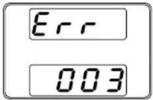 |
| Overview | The Remove Test function will delete a test script from the internal memory. |
| Steps | 1. Select T-04 (Test Remove) and choose which test script to remove from the internal memory.T-04 range 1~102. The test script will be removed from the internal memory. |
| Overview | The T-05 function displays the amount of internal memory that is left on the unit to load test scripts. The displayed units are in kilobytes (1024 bytes). | |
| Steps | Select T-05 (Test Memory). The available memory in kilobytes is displayed.T-05 range 1~1848 KB | Page 89 |
CONFIGURATION
Configuration 97
Configuration Table 97 Normal Function Settings 102 USB/GPIB Settings 106 LAN Settings....107 System Settings....108 Power On Configuration Settings....110 Calibration 111Configuration
Configuration of the PSW power supplies is divided into five different configuration settings: Normal Function, USB/GPIB, LAN, Power ON Configuration, Calibration Settings and System Settings. Power ON Configuration differs from the other settings in that the settings used with Power ON Configuration settings can only be set during power up. The other configuration settings can be changed when the unit is already on. This prevents some important configuration parameters from being changed inadvertently. Power On Configuration settings are numbered F-90 to F-95 and the other configuration settings are numbered F-00 to F-61 and F-88 to F-89.Configuration Table
Please use the configuration settings listed below when applying the configuration settings.| Normal Function | ||
| Settings | Setting | Setting Range |
| Output ON delay time | F-01 | 0.00s~99.99s |
| Output OFF delay time | F-02 | 0.00s~99.99s |
| V-I mode slew rate select | F-03 | 0 = CV high speed priority1 = CC high speed priority2 = CV slew rate priority3 = CC slew rate priority |
| Rising voltage slew rate | F-04 | 0.01V/s~60.00V/s (PSW 30-XX)0.1V/s~160.0V/s (PSW 80-XX)0.1V/s~320.0V/s (PSW 160-XX)0.1V/s~500.0V/s (PSW 250-XX)1V/s~1600V/s (PSW 800-XX) |
| Falling voltage slew rate | F-05 | 0.01V/s~60.00V/s (PSW 30-XX)0.1V/s~160.0V/s (PSW 80-XX)0.1V/s~320.0V/s (PSW 160-XX)0.1V/s~500.0V/s (PSW 250-XX)1V/s~160OVS (PSW 800-XX) |
| Rising current slew rate F-06 | 0.01A/s~72.00A/s (PSW 30-36)0.1A/s~144.0A/s (PSW 30-72)0.1A/s~216.0A/s (PSW 30-108)0.01A/s~27.00A/s (PSW 80-13.5)0.01A/s~54.00A/s (PSW 80-27)0.01A/s~81.00A/s (PSW 80-40.5)0.01A/s~14.40A/s (PSW 160-7.2)0.01A/s~28.80A/s (PSW 160-14.4)0.01A/s~43.20A/s (PSW 160-21.6)0.001A/s ~ 9.000A/s (PSW 250-4.5)0.01A/s ~ 18.00A/s (PSW 250-9)0.01A/s ~ 27.00A/s (PSW 250-13.5)0.001A/s ~ 2.880A/s (PSW 800-1.44)0.001A/s ~ 5.760A/s (PSW 800-2.88)0.001A/s ~ 8.640A/s (PSW 800-4.32) | |
| Falling current slew rate F-07 | 0.01A/s~72.00A/s (PSW 30-36)0.1A/s~144.0A/s (PSW 30-72)0.1A/s~216.0A/s (PSW 30-108)0.01A/s~27.00A/s (PSW 80-13.5) 0.01A/s~54.00A/s (PSW 80-27)0.01A/s~81.00A/s (PSW 80-40.5)0.01A/s~14.40A/s (PSW 160-7.2)0.01A/s~28.80A/s (PSW 160-1.44)0.01A/s~43.20A/s (PSW 160-21.6)0.001A/s ~ 9.000A/s (PSW 250-4.5)0.01A/s ~ 18.00A/s (PSW 250-9)0.01A/s ~ 27.00A/s (PSw 250-13.5)0.001A/s ~ 2.880A/s (PSW 800-1.44)0.001A/s ~ 5.760A/s (PSW 800-2.88)0.001A/s ~ 8.640A/s (PSW 800-4.32) | |
| Internal resistance setting | F-08 | 0.000Ω~0.833Ω (PSW 30-36)0.000Ω~0.417Ω (PSW 30-72)0.000Ω~0.278Ω (PSW 30-108)0.000Ω~5.926Ω (PSW 80-13.5)0.000Ω~2.963Ω (PSW 80-27)0.000Ω~1.975Ω (PSW 80-40.5)0.000Ω~22.222Ω (PSW 160-7.2)0.000Ω~11.111Ω (PSW 160-14.4)0.000Ω~7.407Ω (PSW 160-21.6)0.00Ω ~ 55.55Ω (PSW 250-4.5)0.00Ω ~ 27.77Ω (PSW 250-9)0.00Ω ~ 18.51Ω (PSW 250-13.5)0.0Ω ~ 555.5Ω (PSW 800-1.44)0.0Ω ~ 277.8Ω (PSW 800-2.88)0.0Ω ~ 185.1Ω (PSW 800-4.32) |
| Bleeder circuit control | F-09 | 0 = OFF, 1 = ON, 2 = AUTO |
| Buzzer ON/OFF control | F-10 | 0 = OFF, 1 = ON |
| Measurement Average Setting | F-17 | 0 = Low, 1 = Middle, 2 = High |
| Lock Mode | F-19 | 0 = Panel lock: allow output off1 = Panel lock: allow output on/off |
| USB/GPIB settings | ||
| Front panel USB State | F-20 | 0 = Absent, 1 = Mass Storage |
| Rear panel USB State | F-21 | 0 = Absent, 2 = USB-CDC, 3 = GPIB-USB adapter |
| Rear panel USB mode | F-22 | 0 = Disable, 1 = GPIB-USB adapter,2 = Auto detect speed, 3 = Full speed only |
| GPIB address | F-23 | 0~30 |
| LAN settings | ||
| MAC Address-1 | F-30 | 0x00~0xFF |
| MAC Address-2 | F-31 | 0x00~0xFF |
| MAC Address-3 | F-32 | 0x00~0xFF |
| MAC Address-4 | F-33 | 0x00~0xFF |
| MAC Address-5 | F-34 | 0x00~0xFF |
| MAC Address-6 | F-35 | 0x00~0xFF |
| LAN | F-36 | 0 = Disable, 1 = Enable |
| DHCP | F-37 | 0 = Disable, 1 = Enable |
| IP Address-1 | F-39 | 0~255 |
| IP Address-2 | F-40 | 0~255 |
| IP Address-3 | F-41 | 0~255 |
| IP Address-4 | F-42 | 0~255 |
| Subnet Mask-1 | F-43 | 0~255 |
| Subnet Mask-2 | F-44 | 0~255 |
| Subnet Mask-3 | F-45 | 0~255 |
| Subnet Mask-4 | F-46 | 0~255 |
| Gateway-1 | F-47 | 0~255 |
| Gateway-2 | F-48 | 0~255 |
| Gateway-3 | F-49 | 0~255 |
| Gateway-4 | F-50 | 0~255 |
| DNS address -1 | F-51 | 0~255 |
| DNS address -2 | F-52 | 0~255 |
| DNS address-3 | F-53 | 0~255 |
| DNS address-4 | F-54 | 0~255 |
| Sockets active | F-57 | 0 = Disable, 1 = Enable |
| Web Server active | F-59 | 0 = Disable, 1 = Enable |
| Web password active | F-60 | 0 = Disable, 1 = Enable |
| Web setting password | F-61 | 0000~9999 |
| System Settings | ||
| Factory Set Value | F-88 | 0 = Disable1 = Return to factory settings |
| Show Version | F-89 | 0, 1 = PSW version2, 3 = PSW build year4, 5 = PSW build month/day6, 7 = Keyboard CPLD version8, 9 = Analog-Control CPLD versionA, B = ReservedC, D = Kernel build yearE, F = Kernel build month/dayG, H = Test command versionI, J = Test command build yearK, L = Test command build month/dayM, N = USB Driver version. |
| CV Control | F-90 | 0 = Panel control (local)1 = External voltage control2 = External resistance control(Ext-R10kΩ = Vo, max)3 = External resistance control(Ext-R10kΩ = 0) |
| CC Control | F-91 | 0 = Panel control (local)1 = External voltage control2 = External resistance control(Ext-R10kΩ = Io,max)3 = External resistance control(Ext-R10kΩ = 0) |
| Power-ON Output | F-92 | 0 = OFF at startup1 = ON at startupT001 ~ T010 = Run test script TXX at start up |
| Master/Slave | F-93 | 0 = Master/Local1 = Master/Parallel12 = Master/Parallel23 = Slave/Parallel4 = Slave/Series (Only 30V, 80V, 160V models) |
| External Out Logic | F-94 | 0 = High ON, 1 = Low ON |
| Power Switch trip | F-95 | 0 = Enable, 1 = Disable |
| Calibration Settings* | ||
| Calibration | F-00 | 0000 ~ 9999 |
Normal Function Settings
Output ON Delay Time
Delays turning the output on for a designated amount of time. The Delay indicator will light when the Delay time is not 0. Note: The Output ON Delay Time setting has a maximum deviation (error) of 20ms. The Output ON Delay Time setting is disabled when the output is set to external control.  F-01 0.00s\~99.99sOutput OFF Delay Time
Delays turning the output off for a designated amount of time. The Delay indicator will light when the Delay time is not 0. Note: The Output OFF Delay Time setting has a maximum deviation (error) of 20ms. The Output OFF Delay Time setting is disabled when the output is set to external control.  F-02 0.00s\~99.99sV-I Mode
Selects High Speed Priority or Slew Rate Priority for CV or CC mode. The voltage or current slew rate can only be edited if CC/CV Slew Rate Priority is selected. The ISR indicator will be lit for CC Slew Rate Priority and the VSR indicator will be lit for CV Slew Rate Priority. Note: CC and CV Slew Rate Priority mode are disabled when voltage/current output is set to external control.  F-03  0 = CV high speed priority 1 = CC high speed priority 2 = CV slew rate priority 3 = CC slew rate priorityRising Voltage Slew Rate
Sets the rising voltage slew rate. Only applicable if V-I Mode is set to CV Slew Rate Priority. F-04 0.01V/s\~60V/s (PSW 30-XX) 0.1V/s\~160V/s (PSW 80-XX) 0.1V/s\~320V/s (PSW 160-XX) 0.1V/s\~500.0V/s (PSW 250-XX) 1V/s\~1600V/s (PSW 800-XX)| Falling Voltage Slew Rate | Sets the falling voltage slew rate. Only applicable if V-I Mode is set to CV Slew Rate Priority. | |
| F-05 | 0.01V/s~60V/s (PSW 30-XX) | |
| 0.1V/s~160V/s (PSW 80-XX) | ||
| 0.1V/s~320V/s (PSW 160-XX) | ||
| 0.1V/s~500.0V/s (PSW 250-XX) | ||
| 1V/s~1600V/s (PSW 800-XX) | ||
| Rising Current Slew Rate | Sets the rising current slew rate. Only applicable if V-I Mode is set to CC Slew Rate Priority. | |
| F-06 | 0.01A/s~72.00A/s (PSW 30-36) | |
| 0.1A/s~144.0A/s (PSW 30-72) | ||
| 0.1A/s~216.0A/s (PSW 30-108) | ||
| 0.01A/s~27.00A/s (PSW 80-13.5) | ||
| 0.01A/s~54.00A/s (PSW 80-27) | ||
| 0.01A/s~81.00A/s (PSW 80-40.5) | ||
| 0.01A/s~14.40A/s (PSW 160-7.2) | ||
| 0.01A/s~28.80A/s (PSW 160-14.4) | ||
| 0.01A/s~43.20A/s (PSW 160-21.6) | ||
| 0.001A/s~9.000A/s (PSW 250-4.5) | ||
| 0.01A/s~18.00A/s (PSW 250-9) | ||
| 0.01A/s~27.00A/s (PSW 250-13.5) | ||
| 0.001A/s~2.880A/s (PSW 800-1.44) | ||
| 0.001A/s~5.760A/s (PSW 800-2.88) | ||
| 0.001A/s~8.640A/s (PSW 800-4.32) | ||
| Falling Current Slew Rate | Sets the falling current slew rate. Only applicable if V-I Mode is set to CC Slew Rate Priority. | |
| F-07 | 0.01A/s~72.00A/s (PSW 30-36) | |
| 0.1A/s~144.0A/s (PSW 30-72) | ||
| 0.1A/s~216.0A/s (PSW 30-108) | ||
| 0.01A/s~27.00A/s (PSW 80-13.5) | ||
| 0.01A/s~54.00A/s (PSW 80-27) | ||
| 0.01A/s~81.00A/s (PSW 80-40.5) | ||
| 0.01A/s~14.40A/s (PSW 160-7.2) | ||
| 0.01A/s~28.80A/s (PSW 160-14.4) | ||
| 0.01A/s~43.20A/s (PSW 160-21.6) | ||
| 0.001A/s~9.000A/s (PSW 250-4.5) | ||
| 0.01A/s~18.00A/s (PSW 250-9) | ||
| 0.01A/s~27.00A/s (PSW 250-13.5) | ||
| 0.001A/s~2.880A/s (PSW 800-1.44) | ||
| 0.001A/s~5.760A/s (PSW 800-2.88) | ||
| 0.001A/s~8.640A/s (PSW 800-4.32) | ||
| Internal Resistance Settings | Sets the internal resistance of the power supply. | |
| F-08 | 0.000Ω ~0.833Ω (PSW 30-36) | |
| 0.000Ω ~0.417Ω (PSW 30-72) | ||
| 0.000Ω ~0.278Ω (PSW 30-108) | ||
| 0.000Ω ~5.926Ω (PSW 80-13.5) | ||
| 0.000Ω ~2.963Ω (PSW 80-27) | ||
| 0.000Ω ~1.975Ω (PSW 80-40.5) | ||
| 0.000Ω ~22.222Ω (PSW 160-7.2) | ||
| 0.000Ω ~11.111Ω (PSW 160-14.4) | ||
| 0.000Ω ~7.407Ω (PSW 160-21.6) | ||
| 0.00Ω ~55.55Ω (PSW 250-4.5) | ||
| 0.00Ω ~27.77Ω (PSW 250-9) | ||
| 0.00Ω ~18.51Ω (PSW 250-13.5) | ||
| 0.0Ω ~555.5Ω (PSW 800-1.44) | ||
| 0.0Ω ~277.8Ω (PSW 800-2.88) | ||
| 0.0Ω ~185.1Ω (PSW 800-4.32) | ||
| Bleeder Control | Bleeder control turns ON/OFF the bleeder resistor. When set to AUTO the bleeder resistor is automatically turned on when the output is turned on and turned off when the output is turned off. Bleeder resistors discharge the filter capacitors after power is turned off as a safety measure.The AUTO setting is only applicable to firmware version 1.59 or above.F-09 0 = OFF, 1 = ON, 2 = AUTO |
| Buzzer ON/OFF | Turns the buzzer sound on or off. The buzzer is associated with alarm sounds and keypad entry sounds.F-10 0 = OFF, 1 = ON |
| Measurement Average Setting | Determines the level of smoothing for the average setting.Only available for firmware version 1.5 or above.F-17 0 = Low, 1 = Middle, 2 = High |
| Lock Mode | Determines the behavior of the Output key when the panel lock is on.Only available for firmware version 1.54 or above.F-19 0 = Panel lock: allow output off, 1 = Panel lock: allow output on/off |
| Front Panel USB State | Displays the front panel USB-A port state. This setting is not configurable. | |
| F-20 | 0 = Absent, 1 = Mass Storage | |
| Rear Panel USB State | Displays the rear panel USB-B port state. This setting is not configurable.F-21 0 = Absent, 2 = USB-CDC,3 = GPIB-USB adapter | |
| Rear Panel USB Mode | Sets the rear panel USB mode.Note: Option #3, USB CDC Full Speed Only, can be used to reduce the data transmission speed when there are sources of interference in the operating environment. This option is only available for firmware version 1.42 and above.F-22 0 = Disable, 1 = GPIB-USB adapter,2 = Auto detect speed,3 = Full speed only | |
| GPIB Address | Sets the GPIB address.F-23 0~30 | |
| MAC Address-1~6 | Displays the MAC address 1~6. This setting is not configurable.F-30~F-35 0x00~0xFF | |
| LAN | Turns Ethernet on or off.F-36 0 = Disable, 1 = Enable | |
| DHCP | Turns DHCP on or off.F-37 0 = Disable, 1 = Enable | |
| IP Address-1~4 | Sets the default IP address. IP address 1~4 splits the IP address into four sections.(F-39 : F-40 : F-41 : F-42)(0~255 : 0~255 : 0~255 : 0~255) | |
| Subnet Mask 1~4 | Sets the subnet mask. The subnet mask is split into four parts.(F-43 : F-44 : F-45: F-46)(0~255 : 0~255 : 0~255 : 0~255) | |
| Gateway 1~4 | Sets the gateway address. The gateway address is split into 4 parts.(F-47 : F-48 : F-49 : F-50)(0~255 : 0~255 : 0~255 : 0~255) | |
| DNS Address 1~4 | Sets the DNS address. The DNS address is split into 4 parts.(F-51 : F-52 : F-53 : F-54)(0~255 : 0~255 : 0~255 : 0~255) | |
| Sockets active | Enables WebSocket connections.F-57 0 = Disable, 1 = Enable | |
| Web server active | Turns Web server control on/off.F-59 0 = Disable, 1 = Enable | |
| Web Password active | Turns a web password on/off.F-60 0 = Disable, 1 = Enable | |
| Web Password | Sets the Web password.F-61 0000 ~ 9999 | |
| Factory Set Value | Returns the PSW to the factory default settings. See page 158 for a list of the default settings. F-88 | 0 = Disable, 1 = Return to factory default settings. |
| Displays the PSW version number, build date, keyboard version, analog-control version, kernel build, test command version and test command build date. | |
| Show Version | 0, 1 = PSW version2, 3 = PSW build year4, 5 = PSW build month/day6, 7 = Keyboard CPLD version8, 9 = Analog-Control CPLD version |
| F-89 | A, B = ReservedC, D = Kernel build yearE, F = Kernel build month/dayG, H = Test command versionI, J = Test command build yearK, L = Test command build month/dayM, N = USB Driver version |
| CV Control | Sets the constant voltage (CV) control mode between local and external voltage/resistance control. For external voltage control, see page 119 (External Voltage Control of Voltage Output) and page 124 (External Resistance Control of Voltage Output).F-90 0= Panel control (local)1 = External voltage control2 = External resistance control(Ext-R10kΩ = Vo,max)3 = External resistance control(Ext-R10kΩ = 0) | |
| CC Control | Sets the constant current (CC) control mode between local and external voltage/resistance control. For details on external voltage control, see page 122 (External Voltage Control of Current Output) and 126 (External Resistance Control of Current Output).F-91 0= Panel control (local)1 = External voltage control2 = External resistance control(Ext-R10kΩ = Io,max)3 = External resistance control(Ext-R10kΩ = 0) | |
| Power-ON Output | Configures the power supply to do one of the following at startup: keep the output off, turn the output on, or load a test script.F-92 0 = OFF at startup1 = ON at startupT001 ~ T010 = Run test script TXX at start up | |
| Master/Slave | Sets the power supply as master or slave. See the parallel/series operation for details, page 72. | |
| F-93 | 0 = Master/Local1 = Master/Parallel12 = Master/Parallel23 = Slave/Parallel4 = Slave/Series (Only for 30V, 80V, 160V models) | |
| External Out Logic | Sets the external logic as active high or low. | |
| F-94 | 0= High ON, 1 = Low ON | |
| Power Switch Trip | Turns the power off if enabled when the protection settings are tripped. |
| F-95 1 = Disable, 0 = Enable |
| Programmable Calibration | The calibration password is used to access the local mode calibration or other special functions. The password used determines which function is accessed. Please see your distributor for details. | |
| F-00 | 0000 ~ 9999 | |
Setting Normal Function Settings
| The normal function settings (F-01~F-61, F-88~F-89) can be easily configured with the Function key.Ensure the load is not connected.Ensure the output is off. | |
| Note | Function setting F-89 (Show Version) can only be viewed, not edited.Configuration settings F-90~F-95 cannot be edited in the Normal Function Settings. Use the Power On Configuration Settings. See page 114 for details. |
Steps
1. Press the Function key. The function key will light up.  2. The display will show F-01 on the top and the configuration setting for F-01 on the bottom.  3. Rotate the Voltage knob to change the F setting. Range F-00\~F-61, F-88\~F-89  4. Use the Current knob to set the parameter for the chosen F setting.  5. Press the Voltage knob to save the configuration setting. ConF will be displayed when successful.   Exit Press the Function key again to exit the configuration settings. The function key light will turn off. Function Setting Power On Configuration Settings
Background
The Power On configuration settings can only be changed during power up to prevent the configuration settings being inadvertently changed. - Ensure the load is not connected. • Ensure the power supply is off.Steps
1. Hold the Function key whilst turning the power on. 2. The display will show F-90 on the top and the configuration setting for F-90 on the bottom.   5. Press the Voltage knob to save the configuration setting. ConF will be displayed when successful.   Exit Cycle the power to save and exit the configuration settings.ANALOG CONTROL
The Analog Control chapter describes how to control the voltage or current output using an external voltage or resistance, monitor the voltage or current output as well as remotely turning off the output or shutting down the power supply.Analog Remote Control Overview ....117
Analog Control Connector Overview....117 External Voltage Control of Voltage Output 119 External Voltage Control of Current Output 122 External Resistance Control of Voltage Output 124 External Resistance Control of Current Output 126 External Control of Output 128 External control of Shutdown 131Remote Monitoring ....133
External Voltage and Current Monitoring....133 External Operation and Status Monitoring......135Analog Remote Control Overview
The PSW power supply series have a number of analog control options. The Analog Control connectors are used to control output voltage and current using external voltage or resistance. The power supply output and power switch can also be controlled using external switches. - Analog Control connector overview from page 117 - External voltage control of voltage output from page 119 - External voltage control of current output from page 122 - External resistance control of voltage output → from page 124 - External resistance control of current output → from page 126 - External control of output from page 128 - External control of the power switch from page 131 Analog Control Connector Overview| Overview | The Analog Control Connector is a standard Mil 26 pin connector (OMRON XG4 IDC plug). The connector is used for all analog remote control. The pins used determine what remote control mode is used. |
 WARNING WARNING | To prevent electric shock, ensure that the cover for the Analog Control Connector is used when the connector is not in use. |
| Pin Assignment | 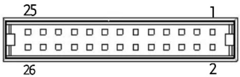 |
| Pin name | Pin number Description |
| Current Share | 1 Used when operating 2 or more units in parallel. |
| D COM | 2 | Connected to the (-S) sense- terminal when remote sense is used. Connected to the negative output terminal when remote sense is not used. |
| CURRENT SUM OUT | 3 | Current sum output signal when used in parallel mode. |
| EXT-V CV CONT | 4 | External voltage control of the voltage output. A voltage of 0~10V is used to control the full scale voltage output (0%~100%) of the instrument. |
| EXT-V CC CONT | 5 | External voltage control of the current output. A voltage of 0~10V is used to control the full scale current output (0%~100%) of the instrument |
| EXT-R CV CONT PIN1 | 6 | External resistance control of the voltage output. A resistance of 0kΩ ~ 10kΩ is used to control the full scale voltage output (0%~100%) of the instrument. |
| EXT-R CV CONT PIN2 | 7 | External resistance control of the voltage output. A resistance of 0kΩ ~ 10kΩ is used to control the full scale voltage output (0%~100%) of the instrument. |
| EXT-R CC CONT PIN1 | 8 | External resistance control of the current output. A resistance of 0kΩ ~ 10kΩ is used to control the full scale current output (0%~100%) of the instrument. |
| EXT-R CC CONT PIN2 | 9 | External resistance control of the current output. A resistance of 0kΩ ~ 10kΩ is used to control the full scale current output (0%~100%) of the instrument. |
| V MON | 10 | Voltage Monitor Output. Outputs the full scale voltage (0~100%) as a voltage (0V~10V). |
| I MON | 11 | Current Monitor Output. Outputs the full scale current (0~100%) as a voltage (0V~10V). |
| SHUTDOWN | 12 | The shut down signal will turn off the output or power when a low TTL signal is applied. The shutdown signal is pulled up to 5V with a 10kΩ pull-up resistor. |
| CURRENT_SUM_1 | 13 | Master unit current sum input signal from first slave CURRENT SUM OUTPUT. Used in parallel mode only. |
| CURRENT_SUM_2 | 14 | Master unit current sum input signal from second slave CURRENT SUM OUTPUT. Used in parallel mode only. |
| FEEDBACK | 15 | Parallel control signal during master-slave parallel operation. |
| A COM | 16 Analog signal common. Connected to the sense-terminal when remote sense is used. Connected to the negative output terminal when remote sense is not used. |
| STATUS COM | 17 Common for status signals 18, 19, 20, 21 and 22. |
| CV STATUS | 18 Turns on when CV mode is active. (photo coupled open collector output) |
| CC STATUS | 19 Turns on when CC mode is active. (photo coupled open collector output) |
| ALM STATUS | 20 Turns on when any of the protection modes are tripped (OVP, OCP) or if a shutdown signal is input. (photo coupled open collector output) |
| OUTPUT ON STATUS | 21 Turns on when the output has been turned on. (photo coupled open collector output) |
| POWER OFF STATUS | 22 Turns on when the power switch is turned off. |
| N.C. | 23 Not connected |
| OUT ON/OFF CONT | 24 Turns the output on/off when (default setting) a low TTL signal is applied. Internally, the circuit is pulled up to +5V with 10kΩ resistance. |
| SER SLV IN | 25 Series slave input during master-slave series operation. (30V/80V/160V models only) |
| N.C. | 26 Not connected |
External Voltage Control of Voltage Output
Background External voltage control of the voltage output is accomplished using the MIL-26 connector on the rear panel. A voltage of 0\~10V is used to control the full scale voltage of the instrument, where: Output voltage = full scale voltage × (external voltage/10)Connection
When connecting the external voltage source to the MIL connectors, use shielded or twisted paired wiring.  - Pin16 EXT-V (-) - Pin4 EXT-V (+) - Wire shield → negative (-) output terminal Connection-alt. shielding If the wire shield needs to be grounded at the voltage source (EXT-V), then the shield cannot also be grounded at the negative (-) terminal output of the PSW power supply. This would short the output.  - Pin16 → EXT-V(-) - Pin4 EXT-V(+) - Wire shield EXT-V ground (GND) Panel operation 1. Connect the external voltage according to the connection diagrams above.| 2. Set the F-90 power on configuration setting to 1 (CV control - Ext voltage).Be sure to cycle the power after the power on configuration has been set. | Page 114 | |
| 3. Press the Function key and confirm the new configuration settings (F-90=1). | Function | |
| 4. Press the Output key. The voltage can now be controlled with the External voltage. | Output | |
| Note | The input impedance for external voltage control is 10kΩ.Use a stable voltage supply for the external voltage control. | |
| Note | CV and CC Slew Rate Priority are disabled for V-I mode (F-03) when using external voltage control.See the normal function settings on page 102. | |
| CAUTION | Ensure no more than 10.5 volts are input into the external voltage input.Ensure the voltage polarity is correct when connecting the external voltage. | |
External Voltage Control of Current Output
Background
External voltage control of the current output is accomplished using the MIL-26 connector on the rear panel. A voltage of 0\~10V is used to control the full scale current of the instrument, where: Output current = full scale current × (external voltage/10)Connection
When connecting the external voltage source to the MIL connectors, use shielded or twisted paired wiring.  \- Pin16 EXT-V (-) \- Pin5 → EXT-V (+) • Wire shield → negative (-) output terminal Connection-alt. shielding If the wire shield needs to be grounded at the voltage source (EXT-V), then the shield cannot also be grounded at the negative (-) terminal output of the PSW power supply. This would short the output.  - Pin16 → EXT-V (-) - Pin5 EXT-V (+) - Wire shield EXT-V ground (GND) Steps 1. Connect the external voltage according to the connection diagrams above. 2. Set the F-91 power on configuration setting to 1 (CC control - Ext voltage). Page 114 \- Be sure to cycle the power after the power on configuration has been set. 3. Press the Function key and confirm the new configuration settings (F-91=1).  4. Press the Output key. The current can now be controlled with the External voltage. | Note | The input impedance for external voltage control is 10kΩ.Use a stable voltage supply for the external voltage control. |
| Note | CV and CC Slew Rate Priority are disabled for V-I mode (F-03) when using external voltage control.See the normal function settings on page 102. |
| CAUTION | Ensure the voltage polarity is correct when connecting the external voltage.Ensure no more than 10.5 volts are input into the external voltage input. |
| Background | External resistance control of the voltage output is accomplished using the MIL-26 connector on the rear panel. A resistance of 0kΩ~10kΩ is used to control the full scale voltage of the instrument.The output voltage (0 to full scale) can be controlled with the external resistance going up (Ext-R √) 0kΩ~10kΩ(10kΩ = Vo,max) or down (Ext-R △) 10kΩ~0kΩ(10kΩ = 0).For 0kΩ~10kΩ: Output voltage = full scale voltage × (external resistance/10)For 10kΩ~0kΩ: Output voltage = full scale voltage × ([10-external resistance]/10) |
Note
The Ext-R configuration is recommended for safety reasons. In the event that the cables become accidentally disconnected, the voltage output will drop to zero. Under similar circumstances using Ext-R, an unexpected high voltage would be output. If switches are used to switch between fixed resistances, use switches that avoid creating open circuits. Use short-circuit or continuous resistance switches.Connection
 - Pin6 EXT-R - Pin7 EXT-R • Wire shield → negative (-) output terminalSteps
1. Connect the external resistance according to the connection diagrams above. 2. Set the F-90 (CV Control) Page 114 configuration settings to 2 for Ext-R or 3 for Ext-R. \- Be sure to cycle the power after the power on configuration has been set. 3. Press the Function key and confirm the new configuration settings (F-90=2 or 3). Function | 4. Press the Output key. The voltage can now be controlled with the External resistance. | Output | |
| Note | Ensure the resistor(s) and cables used exceed the isolation voltage of the power supply. For example: insulation tubes with a withstand voltage higher than the power supply can be used.When choosing an external resistor ensure the resistor can withstand a high degree of heat. | |
| Note | CV and CC Slew Rate Priority are disabled for V-I mode (F-03) when using external resistance control. See the normal function settings on page 102. | |
| External Resistance Control of Current Output | ||
| Background | External resistance control of the current output is accomplished using the MIL-26 connector on the rear panel. A resistance of 0kΩ~10kΩ is used to control the full scale current of the instrument.The output current (0 to full scale) can be controlled with the external resistance going up (Ext-R √) 0kΩ~10kΩ(10kΩ = Vo,max) or down (Ext-R) 10kΩ~0kΩ(10kΩ = 0).For 0kΩ~10kΩ: Output current = full scale current × (external resistance/10)For 10kΩ~0kΩ: Output current = full scale current × ([10-external resistance]/10) | |
Note
The Ext-R configuration is recommended for safety reasons. In the event that the cables become accidentally disconnected, the current output will drop to zero. Under similar circumstances using Ext-R, an unexpected high current would be output. If switches are used to switch between fixed resistances, use switches that avoid creating open circuits. Use short-circuit or continuous resistance switches.Connection
 - Pin9 EXT-R - Pin8 EXT-R • Wire shield → negative (-) output terminalSteps
1. Connect the external resistance according to the connection diagrams above. 1. Set the F-91 (CC Control) Page 114 configuration settings to 2 for Ext-R or 3 for Ext-R. \- Be sure to cycle the power after the power on configuration has been set. 2. Press the Function key and confirm the new configuration settings (F-91=2 or 3). Function 3. Press the Output key. The current output can now be controlled with the External resistance.  | |
 | Ensure the resistor(s) and cables used exceed the isolation voltage of the power supply. For example: insulation tubes with a withstand voltage higher than the power supply can be used.When choosing an external resistor ensure the resistor can withstand a high degree of heat. |
 | CV and CC Slew Rate Priority are disabled for V-I mode (F-03) when using external resistance control. See the normal function settings on page 102. |
External Control of Output
Background
The output can be turned on or off externally using a switch. The analog control connector can be set to turn the output on from a high or low signal. The voltage across pins 2 and 24 are internally pulled to +5V ±5% @ 500uA with 10kΩ pull-up resistor. A short (closed switch) produces a low signal. When set to High = On, the output is turned on when the pins 2-24 are open. When Low = On, the output is turned on when pins 2-24 are shorted.Connection
PSWSwi  - Pin2 Switch - Pin24 → Switch - Wire shield → negative (-) output terminalSteps
1. Connect the external switch according to the connection diagrams above. Set F-94 (External output logic) in Page 114 the power on configuration settings to 0 (High = On) or 1 (Low = On). \- Be sure to cycle the power after setting the power on configuration settings. 2. Press the Function key and confirm the new configuration settings. Function  3. The switch is now ready to set the output on or off.  When using a switch over long distances, please use a switch relay to extend the line from the coil side of the relay. flowchart
graph LR
    A["Line extension"] --> B["Switch Relay"]
    B --> C["Analog connector"]
    B -->|2| C
    B -->|24| C
External control of Shutdown
Background
The output of the power supplies can be configured to shut down via an external switch. The ability to externally shut down the power supply must first be enabled in the power on configuration settings. The voltage across pins 2 and 12 are internally pulled to +5V ±5% @ 500uA with 10kΩ pull-up resistor.Connection
 - Pin2 Switch - Pin12 Switch • Wire shield → negative (-) output terminalSteps
1. Connect the external switches according to the connection diagrams above. 2. Set F-95 to in the configuration settings to 0 (Enable). This will allow the external control of shutdown. Page 114 3. Press the function key and confirm the new configuration settings. Function  4. The switch will now shut down the power supply when shorted.  When using a switch over long distances, please use a switch relay to extend the line from the coil side of the relay. flowchart
graph LR
    A["Line extension"] --> B["Switch Relay"]
    B --> C["Analog connector"]
    C --> D["2"]
    C --> E["12"]
Remote Monitoring
The PSW power supplies have remote monitoring support for current and voltage output. They also support monitoring of operation and alarm status. - External monitoring of output voltage and current → from page 133 - External monitoring of operation mode and alarm status → from page 135External Voltage and Current Monitoring
Background
The MIL 26 pin connector is used to monitor the current (IMON) or voltage (VMON) output. An output of 0\~10V represents the voltage or current output of 0\~ rated current/voltage output. - IMON = (current output/full scale) × 10 - VMON = (voltage output/full scale) × 10 External voltage and current monitoring doesn't need to be enabled in the configuration settings.| VMONConnection | 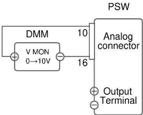 Pin16 → Neg (-)Pin10 → Pos (+) Pin16 → Neg (-)Pin10 → Pos (+) |
| IMONConnection | 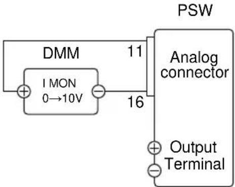 Pin16 → Neg (-)Pin11 → Pos (+) Pin16 → Neg (-)Pin11 → Pos (+) |
 Note Note | The output impedance of the voltage (VMON) and current (IMON) monitor pins is 1kΩ.Maximum current is 10mA.The monitor outputs are strictly DC and should not be used to monitor analog components such as transient voltage response or ripple etc. |
 CAUTION CAUTION | Ensure IMON(pin 11) and VMON(pin 10) are not shorted together. This will cause damage to the unit. |
External Operation and Status Monitoring
Background
The MIL 26 pin connector can also be used to monitor the status operation and alarm status of the instrument. The pins are isolated from the power supply internal circuitry by photo couplers. Status Com (Pin 17) is a photo coupler emitter output, whilst pins 18\~22 are photo coupler collector outputs. A maximum of 30V and 8mA can be applied to each pin.| Name and Pin | Description | |
| STATUS COM | 17 | Common (photo coupler emitter) for status signals 18, 19, 20, 21 and 22. |
| CV STATUS | 18 | Low when CV mode is active. |
| CC STATUS | 19 | Low when CC mode is active. |
| ALM STATUS | 20 | Low when any of the protection modes are tripped (OVP, OCP). Active low. |
| OUT ON STATUS | 21 | Low when the output is on. |
| PWR OFF STATUS | 22 | Active low. |
natural_image
Pure electrical circuit symbol for a diode (no text or labels)Timing diagrams
Below are 4 example timing diagrams covering a number fo scenarios. Note that pins 18\~22 are all active low.CV MODE:
Output turned on
The diagram below shows the timing diagram when the output is turned on when the PSW is set to CV mode. CV MODE:
Output turned off
The diagram below shows the output status lines when the output is turned off in CV mode. CC MODE:
Output turned on The diagram below shows the timing diagram when the output is turned on when the PSW is set to CC mode. CC MODE:
Output turned off The diagram below shows the output status lines when the output is turned off in CC mode. flowchart
graph TD
    A["CV status"] --> B["H"]
    C["CC status"] --> D["L"]
    E["Output status"] --> F["H"]
    G["Output status"] --> H["L"]
COMMUNICATION
INTERFACE
This chapter describes basic configuration of IEEE488.2 based remote control. For a command list, refer to the programming manual, downloadable from GW Instek website, www.gwinstek.comInterface Configuration ....139
USB Remote Interface 139 Configure GPIB Interface....139 Configure Ethernet Connection....141 Web Server Configuration 141 Sockets Server Configuration 142 USB Remote Control Function Check....143 Using Realterm to Establish a Remote Connection....144 Web Server Remote Control Function Check....148Interface Configuration
USB Remote Interface| USB configuration | PC side connector | Type A, host |
| PSW side connector | Rear panel Type B, slave | |
| Speed | 1.1/2.0 (full speed/high speed) | |
| USB Class | CDC (communications device class) |
Steps
1. Connect the USB cable to the rear panel USB B port.  2. Change the Rear panel-USB (F-22) setting to USB-CDC (2). Page 112Configure GPIB Interface
To use GPIB, the optional GPIB to USB (GUG-001) adapter must be used. Only one GPIB address can be used at a time.Configure GPIB
1. Ensure the PSW is off before proceeding. 2. Connect the USB cable from the rear panel USB B port on the PSW to the USB A port on the GPIB to USB adapter. 3. Connect a GPIB cable from a GPIB controller to the GPIB port on the adapter.  4. Turn the PSW on. 5. Press the Function key to enter the Page 112 Normal configuration settings. Set the following GPIB settings F-22 = 1 Set the rear panel USB port to GPIB-USB (GUG-001) F-23 = 0\~30 Set the GPIB address (0\~30) GPIB constraints • Maximum 15 devices altogether, 20m cable length, 2m between each device - Unique address assigned to each device - At least 2/3 of the devices turned On • No loop or parallel connectionConfigure Ethernet Connection
The Ethernet interface can be configured for a number of different applications. Ethernet can be configured for basic remote control or monitoring using a web server or it can be configured as a socket server. The PSW series supports both DHCP connections so the instrument can be automatically connected to an existing network or alternatively, network settings can be manually configured.| Ethernet configuration Parameters | For details on how to configure the Ethernet settings, please see the configuration chapter on page 107. | |
| MAC Address (display only) | LAN | |
| DHCP | IP Address | |
| Subnet Mask | Gateway | |
| DNS Address | Sockets Active | |
| Web Server Active | Web Password Active | |
| Web set password | 0000~9999 (default 0000) | |
Web Server Configuration
Configuration
This configuration example will configure the PSW as a web server and use DHCP to automatically assign an IP address to the PSW. 1. Connect an Ethernet cable from the network to the rear panel Ethernet port.  2. Press the Function key to enter the Page 112 Normal configuration settings. Set the following LAN settings: F-36 = 1 Enable LAN F-37 = 1 Turn DHCP to enable F-59 = 1 Turn the web server on  Note It may be necessary to cycle the power or refresh the web browser to connect to a network.Sockets Server Configuration
Configuration
This configuration example will configure the PSW socket server. The following configuration settings will manually assign the PSW an IP address and enable the socket server. By default, the socket server port number is 2268 and cannot be configured. 1. Connect an Ethernet cable from the network to the rear panel Ethernet port.  2. Press the Function key to enter the Page 112 Normal configuration settings. Set the following LAN settings: F-36 = 1 Enable LAN F-37 = 0 Disable DHCP F-39 = 172 IP Address part 1 of 4 F-40 = 16 IP Address part 2 of 4 F-41 = 5 IP Address part 3 of 4 F-42 = 133 IP Address part 4 of 4 F-43 = 255 Subnet Mask part 1 of 4 F-44 = 255 Subnet Mask part 2 of 4| F-45 = 128 | Subnet Mask part 3 of 4 |
| F-46 = 0 | Subnet Mask part 4 of 4 |
| F-43 = 172 | Gateway part 1 of 4 |
| F-44 = 16 | Gateway part 2 of 4 |
| F-45 = 21 | Gateway part 3 of 4 |
| F-46 = 101 | Gateway part 4 of 4 |
| F-57 = 1 | Enable Sockets |
| Functionality check | Invoke a terminal application such as Realterm. The PSW will appear as a COM port on the PC.To check the COM port No, see the Device Manager in the PC. For WinXP; Control panel → System → Hardware tab. |
| Note | If you are not familiar with using a terminal application to send/receive remote commands via a USB connection, please page 144 (Using Realterm to Establish a Remote Connection) for more information. |
| Run this query command via the terminal after the instrument has been configured for USB remote control (page 139).*idn?This should return the Manufacturer, Model number, Serial number, and Firmware version in the following format.GW-INSTEK,PSW-XXX-X,TW123456,01.00.20110101Manufacturer: GW-INSTEKModel number : PSW-XXX-XSerial number : TW123456Firmware version : 01.00.20110101 | |
 Note Note | For further details, please see the programming manual, available on the GW Instek web site @ www.gwinstek.com. |
| Background | Realterm is a terminal program that can be used to communicate with a device attached to the serial port of a PC or via an emulated serial port via USB.The following instructions apply to version 2.0.0.70. Even though Realterm is used as an example to establish a remote connection, any terminal program can be used that has similar functionality. |
 Note Note | Realterm can be downloaded on Sourceforge.net free of charge.For more information please see http://realterm.sourceforge.net/ |
| Operation | 1. Download Realterm and install according to the instructions on the Realterm website.2. Connect the PSW via USB (page 139).3. Go to the Windows device manager and find the COM port number for the connection. For example, go to the Start menu > Control Panel > Device Manager |
| Functionality check | Enter the IP address of the power supply in a web browser after the instrument has been configured as a web server (page 141).http:// XXX.XXX.XXX.XXSThe web browser interface appears. |
 Note Note | For further details, please see the programming manual, available on the GW Instek web site @ www.gwinstek.com. |
| Background | To test the socket server functionality, National Instruments Measurement and Automation Explorer can be used. This program is available on the NI website, www.ni.com., via a search for the VISA Run-time Engine page, or “downloads” at the following URL, http://www.ni.com/visa/ |
| Requirements | Firmware: V1.12Operating System: Windows XP, 7 |
MAINTENANCE
The PSW power supply filters should be replaced on a periodic schedule to maintain performance and specification characteristics. Replacing the Dust Filter....155Replacing the Dust Filter
The dust filter should be replaced at least 2 times a year. Not replacing the filter on a regular basis will reduce performance and may cause the unit to overheat. Front panel filter (all models) 1. Turn the instrument off. 2. Pull the filter out from the bottom of the front panel. natural_image
Close-up of a finger pressing down on a metallic surface with a downward arrow indicating a contact point (no text or symbols visible)natural_image
Close-up of a hand holding a ruler and pen, with a numbered callout (1) pointing to the pencil tip (no text or symbols on the ruler or background)F_AQ
- The power supply won't let me change the mode (C.V. mode C.C. mode). • The OVP voltage is triggered earlier than expected. • Can I combine more than 1 cable together for the output wiring? • The accuracy does not match the specification. The power supply won't let me change the mode (C.V. mode C.C. mode). To set the power supply to CC or CV mode, the Function key must be held when the power is turned on to enter the Power On Configuration Mode. See page 114. The OVP voltage is triggered earlier than expected. When setting the OVP voltage, take into account the voltage drop from the load cables. As the OVP level is set from the output terminals and not the load terminals, the voltage at the load terminals may be slightly lower. Can I combine more than 1 cable together for the output wiring? Yes. Cables can be used together (in parallel) if the current capacity of a single cable is insufficient. However the withstand voltage should also be taken into account. Ensure the cables are twisted together and are the same length. The accuracy does not match the specification. Make sure the device is powered On for at least 30 minutes, within +20°C\~+30°C. This is necessary to stabilize the unit to match the specification. For more information, contact your local dealer or GWInstek at www.gwinstek.com / marketing@goodwill.com.tw.APPENDIX
PSW Default Settings
The following default settings are the factory configuration settings for the power supply (Function settings/Test settings). For details on how to return to the factory default settings, see page 53.| Initial Settings | Default Setting | |
| Output | Off | |
| LOCK | 0 (Disabled) | |
| Voltage | 0V | |
| Current | 0A | |
| OVP | Maximum | |
| OCP | Maximum | |
| Normal Function | ||
| Settings | Setting | Default Setting |
| Output ON delay time | F-01 | 0.00s |
| Output OFF delay time | F-02 | 0.00s |
| V-I mode slew rate select | F-03 | 0 = CV high speed priority |
| Rising voltage slew rate | F-04 | 60.00V/s (PSW 30-XX) |
| 160.0V/s (PSW 80-XX) | ||
| 320.0V/s (PSW 160-XX) | ||
| 500.0V/s (PSW 250-XX) | ||
| 1600V/s (PSW 800-XX) | ||
| Falling voltage slew rate | F-05 | 60.00V/s (PSW 30-XX) |
| 160.0V/s (PSW 80-XX) | ||
| 320.0V/s (PSW 160-XX) | ||
| 500.0V/s (PSW 250-XX) | ||
| 1600V/s (PSW 80O-XX) | ||
| Rising current slew rate | F-06 | 72.00A/s (PSW 30-36)144.0A/s (PSW 30-72)216.0A/s (PSW 30-108)27.00A/s (PSW 80-13.5)54.00A/s (PSW 80-27)81.00A/s (PSW 80-40.5)14.40A/s (PSW 160-7.2)28.80A/s (PSW 160-14.4)43.20A/s (PSW 160-21.6)9.000A/s (PSW 250-4.5)18.00A/s (PSW 250-9)27.00A/s (PSW 250-13.5)2.880A/s (PSW 800-1.44)5.760A/s (PSW 800-2.88)8.640A/s (PSW 800-4.32) |
| Falling current slew rate | F-07 | 72.00A/s (PSW 30-36)144.0A/s (PSW 30-72)216.0A/s (PSW 30-108)27.00A/s (PSW 80-13.5)54.00A/s (PSW 80-27)81.00A/s (PSW80-40.5)14.40A/s (PSW 160-7.2)28.80A/s (PSW 160-14.4)43.20A/s (PSW 160-21.6)9.000A/s (PSW 250-4.5)18.00A/s (PSW 25O-9)27.00A/s (PSW 250-13.5)2.880A/s (PSW 800-1.44)5.760A/s (PSW 800-2.88)8.640A/s (PSW 800-4.32) |
| Internal resistance setting | F-08 | 0.000Ω |
| Bleeder circuit control | F-09 | 1 = ON |
| Buzzer ON/OFF control | F-10 | 1 = ON |
| Measurement Average Setting | F-17 | 0 = Low |
| Lock Mode | F-19 | 0 = Panel lock: allow output off |
| USB/GPIB setting | ||
| Rear Panel USB Mode | F-22 | 2 = USB CDC |
| GPIB address | F-23 | 8 |
| LAN | F-36 | 1 = Enable |
| DHCP | F-37 | 1 = Enable |
| Sockets active | F-57 | 1 = Enable |
| Web Server active | F-59 | 1 = Enable |
| Web password active | F-60 | 1 = Enable |
| Web setting password | F-61 | 0000 |
| Power On Configuration | ||
| CV Control | F-90 | 0= Panel control (local) |
| CC Control | F-91 | 0= Panel control (local) |
| Power-ON Output | F-92 | 0 = OFF at startup |
| Master/Slave | F-93 | 0 = Master/Local |
| External Out Logic | F-94 | 0= High ON |
| Power Switch trip | F-95 | 0 = Enable |
Error Messages & Messages
The following error messages or messages may appear on the PSW screen during operation.| Error Messages | Description |
| Err 001 | USB Mass Storage is not present |
| Err 002 | No (such)file in USB mass storage |
| Err 003 | Empty memory location |
| Err 004 | File access error |
 Note Note | For error messages other than Err 001 to Err 004, please contact your distributor for service repair. |
| Messages | Description |
| MSG 001 | External control of output. Output off (F-94=0, High=on) |
| MSG 002 | External control of output. Output off (F-94=1, Low=on) |
| MSG 003 | F-93 is not zero. Unable to calibrate. |
| LOCK F-19 | F-19 is zero. Unable to turn the output on. |
LED Display Format
Use the following table to read the LED display messages.| 0 | 1 | 2 | 3 | 4 | 5 | 6 | 7 | 8 | 9 | A | B | C | D |
| 0 | 1 | 2 | 3 | 4 | 5 | 6 | 7 | 8 | 9 | A | b | C | d |
| E | F | G | H | I | J | K | L | M | N | O | P | Q | R |
| E | F | G | H | C | U | E | L | o | P | 9 | r | ||
| S | T | U | V | W | X | Y | Z | ( ) | + | - | , | ||
| S | t | U | 8 | y | c | - | - | ||||||
PSW Specifications
The specifications apply when the PSW is powered on for at least 30 minutes. PSW 360W PSW 30-36, PSW 80-13.5, PSW 160-7.2, PSW 250-4.5, 800-1.44| Model | Unit | PSW30-36 | PSW80-13.5 | PSW160-7.2 | PSW250-4.5 | PSW800-1.44 | |
| Rated Output Voltage | V | 30 | 80 | 160 | 250 | 800 | |
| Rated Output Current | A | 36 | 13.5 | 7.2 | 4.5 | 1.44 | |
| Rated Output Power | W | 360 | 360 | 360 | 360 | 360 | |
| Power Ratio | -- | 3 | 3 | 3.2 | 3.125 | 3.2 | |
| Constant Voltage Mode | |||||||
| Line Regulation (*1) | mV | 18 | 43 | 83 | 128 | 403 | |
| Load Regulation (*2) | mV | 20 | 45 | 85 | 130 | 405 | |
| Ripple and Noise (*3) | |||||||
| p-p (*4) | mV | 60 | 60 | 60 | 80 | 150 | |
| r.m.s (*5) | mV | 7 | 7 | 12 | 15 | 30 | |
| Temperature coefficient | ppm /°C | 100ppm/°C of rated output voltage, after a 30 minute warm-up. | |||||
| Remote sense compensation voltage (single wire) | V | 0.6 | 0.6 | 0.6 | 1 | 1 | |
| Rise Time (*6) | |||||||
| Rated Load | ms | 50 | 50 | 100 | 100 | 150 | |
| No Load | ms | 50 | 50 | 100 | 100 | 150 | |
| Fall Time (*7) | |||||||
| Rated Load | ms | 50 | 50 | 100 | 150 | 300 | |
| No Load | ms | 500 | 500 | 1000 | 1200 | 2000 | |
| Transient response time (*8) | ms | 1 | 1 | 2 | 2 | 2 | |
| Constant Current Mode | |||||||
| Line regulation (*1) | mA | 41 | 18.5 | 12.2 | 9.5 | 6.44 | |
| Load regulation (*9) | mA | 41 | 18.5 | 12.2 | 9.5 | 6.44 | |
| r.m.s (*5) | mA | 72 | 27 | 15 | 10 | 5 |
| Temperature coefficient | ppm /°C | 200ppm/°C of rated output current, after a 30 minute warm-up. | ||||
| Protection Function | ||||||
| Over voltage protection (OVP) | ||||||
| Setting range | V | 3-33 | 8-88 | 16-176 | 20-275 | 20-880 |
| Setting accuracy | ± (2% of rated output voltage) | |||||
| Over current protection (OCP) | ||||||
| Setting range | A | 3.6-39.6 | 1.35-14.85 | 0.72-7.92 | 0.45-4.95 | 0.144-1.584 |
| Setting accuracy | ± (2% of rated output current) | |||||
| Over temperature protection (OTP) | ||||||
| Operation | Turn the output off. | |||||
| Low AC input protection (AC-FAIL) | ||||||
| Operation | Turn the output off. | |||||
| Power limit (POWER LIMIT) | ||||||
| Operation | Over power limit. | |||||
| Value (fixed) | Approx. 105% of rated output power | |||||
| Analog Programming and Monitoring | ||||||
| External voltage control output voltage | Accuracy and linearity: ±0.5% of rated output voltage. | |||||
| External voltage control output current | Accuracy and linearity: ±1% of rated output current. | |||||
| External resistor control output voltage | Accuracy and linearity: ±1.5% of rated output voltage. | |||||
| External resistor control output current | Accuracy and linearity: ±1.5% of rated output current. | |||||
| Output voltage monitor | ||||||
| Accuracy | % | ±1 | ±1 | ±1 | ±2 | ±2 |
| Output current monitor | ||||||
| Accuracy | % | ±1 | ±1 | ±1 | ±2 | ±2 |
| Shutdown control | Turns the output or power off with a LOW (0V to 0.5V) or short-circuit. | |||||
| Output on/off control | Possible logic selections: Turn the output on using a LOW (0V to 0.5V) or short-circuit, turn the output off using a HIGH (4.5V to 5V) or open-circuit. Turn the output on using a HIGH (4.5V to 5V) or open-circuit, turn the output off using a LOW (0V to 0.5V) or short-circuit. | |||||
| CV/CC/ALM/PWR ON/OUTON indicator | Photocoupler open collector output;Maximum voltage 30V, maximum sink current 8mA. | |||||
| Front Panel | ||||||
| Display, 4 digits | ||||||
| Voltage accuracy0.1% + | mV | 20 | 20 | 100 | 200 | 400 |
| Current accuracy0.1% + | mA | 40 | 20 | 5 | 5 | 2 |
| Indications | GREEN LED's: CV, CC, VSR, ISR, DLY, RMT,20, 40, 60, 80, 100, %W, W, V, A | |||||
| RED LED's: ALM | ||||||
| Buttons | Function, OVP/OCP, Set, Test, Lock/Local,PWR DSPL, Output | |||||
| Knobs | Voltage, Current | |||||
| USB port | Type A USB connector | |||||
| Programming and Measurement (USB, LAN, GPIB) | ||||||
| Output voltage programming accuracy 0.1% + | mV | 10 | 10 | 100 | 200 | 400 |
| Output current programming accuracy 0.1% + | mA | 30 | 10 | 5 | 5 | 2 |
| Output voltage programming resolution | mV | 1 | 2 | 3 | 5 | 14 |
| Output current programming resolution | mA | 1 | 1 | 1 | 1 | 1 |
| Output voltage measurement accuracy 0.1% + | mV | 10 | 10 | 100 | 200 | 400 |
| Output current measurement accuracy 0.1% + | mA | 30 | 10 | 5 | 5 | 2 |
| Output voltage measurement resolution | mV | 1 | 2 | 3 | 5 | 14 |
| Output current measurement resolution | mA | 1 | 1 | 1 | 1 | 1 |
| Series and Parallel Capability | ||||||
| Parallel number | Units | 3 | 3 | 3 | 3 | 3 |
| Series Number | Units | 2 | 2 | 2 | None | None |
| Input Characteristics | ||||||
| Nominal input rating | 100Vac to 240Vac, 50Hz to 60Hz, single phase | |||||
| Input voltage range | 85Vac ~ 265Vac | |||||
| Input voltage range | 47Hz ~ 63Hz | |||||
| Maximum input current | ||||||
| 100Vac | A | 5 | ||||
| 200Vac | A | 2.5 | ||||
| Inrush current | Less than 25A. | |||||
| Maximum input power | VA | 500 | ||||
| Power factor | ||||||
| 100Vac | 0.99 | |||||
| 200Vac | 0.97 | |||||
| Efficiency | ||||||
| 100Vac | % | 77 | 78 | 79 | 79 | 80 |
| 200Vac | % | 79 | 80 | 81 | 81 | 82 |
| Hold-up time | 20ms or greater | |||||
| Interface Capabilities | ||||||
| USB | TypeA: Host, TypeB: Slave, Speed: 1.1/2.0, USB Class: CDC(Communications Device Class) | |||||
| LAN | MAC Address, DNS IP Address, User Password, Gateway IP Address, Instrument IP Address, Subnet Mask | |||||
| GPIB | Optional: GUG-001 (GPIB to USB Adapter) | |||||
| Environmental Conditions | ||||||
| Operating temperature | 0°C to 50°C | |||||
| Storage temperature | -25°C to 70°C | |||||
| Operating humidity | 20% to 85% RH; No condensation | |||||
| Storage humidity | 90% RH or less; No condensation | |||||
| Altitude | Maximum 2000m | |||||
| General Specifications | ||
| Weight (main unit only) | kg | Approx. 3kg |
| Dimensions (WxHxD) | mm | 71×124×350 |
| Cooling | Forced air cooling by internal fan. | |
| EMC | Complies with the European EMC directive 2004/108/EC for Class A test and measurement products. | |
| Safety | Complies with the European Low Voltage Directive 2006/95/EC and carries the CE-marking. | |
| Withstand voltage | Between input and chassis: No abnormalities at 1500 Vac for 1 minute. | |
| Between input and output: No abnormalities at 3000 Vac for 1 minute. | ||
| Between output and chassis: No abnormalities at 500 Vdc for 1 minute for 30V, 80V, 160V models. | ||
| No abnormalities at 1500 Vdc for 1 minute for 250V, 800V models. | ||
| Insulation resistance | Between input and chassis: 500 Vdc, 100MΩ or more | |
| Between input and output: 500 Vdc, 100MΩ or more | ||
| Between output and chassis: 500 Vdc, 100MΩ or more for 30V, 80V, 160V and 250V models. | ||
| 1000Vdc, 100MΩ or more for 800V models | ||
| Model | Unit | PSW30-72 | PSW80-27 | PSW160-14.4 | PSW250-9 | PSW800-2.88 |
| Rated Output Voltage | V | 30 | 80 | 160 | 250 | 800 |
| Rated Output Current | A | 72 | 27 | 14.4 | 9 | 2.88 |
| Rated Output Power | W | 720 | 720 | 720 | 720 | 720 |
| Power Ratio | -- | 3 | 3 | 3.2 | 3.125 | 3.2 |
| Constant Voltage Mode | ||||||
| Line Regulation (*1) | mV | 18 | 43 | 83 | 128 | 403 |
| Load Regulation (*2) | mV | 20 | 45 | 85 | 130 | 405 |
| Ripple and Noise (*3) | ||||||
| p-p (*4) | mV | 80 | 80 | 80 | 100 | 200 |
| r.m.s (*5) | mV | 11 | 11 | 15 | 15 | 30 |
| Temperature coefficient | ppm /°C | 100ppm/°C of rated output voltage, after a 30 minute warm-up. | ||||
| Remote sense compensation voltage (single wire) | V | 0.6 | 0.6 | 0.6 | 1 | 1 |
| Rise Time (*6) | ||||||
| Rated Load | ms | 50 | 50 | 100 | 100 | 150 |
| No Load | ms | 50 | 50 | 100 | 100 | 150 |
| Fall Time (*7) | ||||||
| Rated Load | ms | 50 | 50 | 100 | 150 | 300 |
| No Load | ms | 500 | 500 | 1000 | 1200 | 2000 |
| Transient response time (*8) | ms | 1 | 1 | 2 | 2 | 2 |
| Constant Current Mode | ||||||
| Line regulation (*1) | mA | 77 | 32 | 19.4 | 14 | 7.88 |
| Load regulation (*9) | mA | 77 | 32 | 19.4 | 14 | 7.88 |
| Ripple and noise | ||||||
| r.m.s (*5) | mA | 144 | 54 | 30 | 20 | 10 |
| Temperature coefficient | ppm /°C | 200ppm/°C of rated output current, after a 30 minute warm-up. | ||||
| Setting range | V | 3-33 | 8-88 | 16-176 | 20-275 | 20-880 |
| Setting accuracy | ± (2% of rated output voltage) | |||||
| Over current protection (OCP) | ||||||
| Setting range | A | 2.7-5-79.2 | 1.44-29.7 | 15.84 | 0.9-9.9 | 0.288-3.168 |
| Setting accuracy | ± (2% of rated output current) | |||||
| Over temperature protection (OTP) | ||||||
| Operation | Turn the output off. | |||||
| Low AC input protection (AC-FAIL) | ||||||
| Operation | Turn the output off. | |||||
| Power limit (POWER LIMIT) | ||||||
| Operation | Over power limit. | |||||
| Value (fixed) | Approx. 105% of rated output power | |||||
| Analog Programming and Monitoring | ||||||
| External voltage control output voltage | Accuracy and linearity: ±0.5% of rated output voltage. | |||||
| External voltage control output current | Accuracy and linearity: ±1% of rated output current. | |||||
| External resistor control output voltage | Accuracy and linearity: ±1.5% of rated output voltage. | |||||
| External resistor control output current | Accuracy and linearity: ±1.5% of rated output current. | |||||
| Output voltage monitor | ||||||
| Accuracy | % | ±1 | ±1 | ±1 | ±2 | ±2 |
| Output current monitor | ||||||
| Accuracy | % | ±1 | ±1 | ±1 | ±2 | ±2 |
| Shutdown control | Turns the output or power off with a LOW (0V to 0.5V) or short-circuit. | |||||
| Output on/off control | Possible logic selections: Turn the output on using a LOW (0V to 0.5V) or short-circuit, turn the output off using a HIGH (4.5V to 5V) or open-circuit. Turn the output on using a HIGH (4.5V to 5V) or open-circuit, turn the output off using a LOW (0V to 0.5V) or short-circuit. | |||||
| CV/CC/ALM/PWR ON/OUT ON indicator | Photocoupler open collector output; Maximum voltage 30V, maximum sink current &mA. | |||||
| Front Panel | ||||||
| Display, 4 digits | ||||||
| Voltage accuracy0.1% + | mV | 20 | 20 | 100 | 200 | 400 |
| Current accuracy0.1% + | mA | 70 | 40 | 30 | 10 | 4 |
| Indications | GREEN LED's: CV, CC, VSR, ISR, DLY, RMT, 20, 40, 60, 80, 100, %W, W, V, A | |||||
| RED LED's: ALM | ||||||
| Buttons | Function, OVP/OCP, Set, Test, Lock/Local, PWR DSPL, Output | |||||
| Knobs | Voltage, Current | |||||
| USB port | Type A USB connector | |||||
| Programming and Measurement (USB, LAN, GPIB) | ||||||
| Output voltage programming accuracy 0.1% + | mV | 10 | 10 | 100 | 200 | 400 |
| Output current programming accuracy 0.1% + | mA | 60 | 30 | 15 | 10 | 4 |
| Output voltage programming resolution | mV | 1 | 2 | 3 | 5 | 14 |
| Output current programming resolution | mA | 2 | 2 | 2 | 1 | 1 |
| Output voltage measurement accuracy 0.1% + | mV | 10 | 10 | 100 | 200 | 400 |
| Output current measurement accuracy 0.1% + | mA | 60 | 30 | 15 | 10 | 4 |
| Output voltage measurement resolution | mV | 1 | 2 | 3 | 5 | 14 |
| Output current measurement resolution | mA | 2 | 2 | 2 | 1 | 1 |
| Series and Parallel Capability | ||||||
| Parallel number | Units | 3 | 3 | 3 | 3 | 3 |
| Series Number | Units | 2 | 2 | 2 | None | None |
| Input Characteristics | ||||||
| Nominal input rating | 100Vac to 240Vac, 50Hz to 60Hz, single phase | |||||
| Input voltage range | 85Vac ~ 265Vac | |||||
| Input voltage range | 47Hz ~ 63Hz | |||||
| Maximum input current | ||||||
| 100Vac | A | 10 | ||||
| 200Vac | A | 5 | ||||
| Inrush current | Less than 50A. | |||||
| Maximum input power | VA | 1000 | ||||
| Power factor | ||||||
| 100Vac | 0.99 | |||||
| 200Vac | 0.97 | |||||
| Efficiency | ||||||
| 100Vac | % | 77 | 78 | 79 | 79 | 80 |
| 200Vac | % | 79 | 80 | 81 | 81 | 82 |
| Hold-up time | 20ms or greater | |||||
| Interface Capabilities | ||||||
| USB | TypeA: Host, TypeB: Slave, Speed: 1.1/2.0, USB Class: CDC(Communications Device Class) | |||||
| LAN | MAC Address, DNS IP Address, User Password, Gateway IP Address, Instrument IP Address, Subnet Mask | |||||
| GPIB | Optional: GUG-001 (GPIB to USB Adapter) | |||||
| Environmental Conditions | ||||||
| Operating temperature | 0°C to 50°C | |||||
| Storage temperature | -25°C to 70°C | |||||
| Operating humidity | 20% to 85% RH; No condensation | |||||
| Storage humidity | 90% RH or less; No condensation | |||||
| Altitude | Maximum 2000m | |||||
| General Specifications | ||
| Weight (main unit only) | kg | Approx. 5.3kg |
| Dimensions (WxHxD) | mm | 142×124×350 |
| Cooling | Forced air cooling by internal fan. | |
| EMC | Complies with the European EMC directive 2004/108/EC for Class A test and measurement products. | |
| Safety | Complies with the European Low Voltage Directive 2006/95/EC and carries the CE-marking. | |
| Withstand voltage | Between input and chassis: No abnormalities at 1500 Vac for 1 minute. | |
| Between input and output: No abnormalities at 3000 Vac for 1 minute. | ||
| Between output and chassis: No abnormalities at 500 Vdc for 1 minute for 30V, 80V, 160V models. | ||
| No abnormalities at 1500 Vdc for 1 minute for 250V, 800V models. | ||
| Insulation resistance | Between input and chassis: 500 Vdc, 100MΩ or more | |
| Between input and output: 500 Vdc, 100MΩ or more | ||
| Between output and chassis: 500 Vdc, 100MΩ or more for 30V, 80V, 160V and 250V models. | ||
| 1000Vdc, 100MΩ or more for 800V models | ||
PSW 1080W
PSW 30-108, PSW 80-40.5, PSW 160-21.6, PSW 250-13.5, 800-4.32| PSW | PSW | PSW | PSW | PSW | ||
| Model | Unit | 30-108 | 80-40.5 | 160-21.6 | 250-13.5 | 800-4.32 |
| Rated Output Voltage | V | 30 | 80 | 160 | 250 | 800 |
| Rated Output Current | A | 108 | 40.5 | 21.6 | 13.5 | 4.32 |
| Rated Output Power | W | 1080 | 1080 | 1080 | 1080 | 1080 |
| Power Ratio | -- | 3 | 3 | 3.2 | 3.125 | 3.2 |
| Constant Voltage Mode | ||||||
| Line Regulation (*1) | mV | 18 | 43 | 83 | 128 | 403 |
| Load Regulation (*2) | mV | 20 | 45 | 85 | 130 | 405 |
| Ripple and Noise (*3) | ||||||
| p-p (*4) | mV | 100 | 100 | 100 | 120 | 200 |
| r.m.s (*5) | mV | 14 | 14 | 20 | 15 | 30 |
| Temperature coefficient | ppm /°C | 100ppm/°C of rated output voltage, after a 30 minute warm-up. | ||||
| Remote sense compensation voltage (single wire) | V | 0.6 | 0.6 | 0.6 | 1 | 1 |
| Rise Time (*6) | ||||||
| Rated Load | ms | 50 | 50 | 100 | 100 | 150 |
| No Load | ms | 50 | 50 | 100 | 100 | 150 |
| Fall Time (*7) | ||||||
| Rated Load | ms | 50 | 50 | 100 | 150 | 300 |
| No Load | ms | 500 | 500 | 1000 | 1200 | 2000 |
| Transient response time (*8) | ms | 1 | 1 | 2 | 2 | 2 |
| Constant Current Mode | ||||||
| Line regulation (*1) | mA | 113 | 45.5 | 26.6 | 18.5 | 9.32 |
| Load regulation (*9) | mA | 113 | 45.5 | 26.6 | 18.5 | 9.32 |
| Ripple and noise | ||||||
| r.m.s (*5) | mA | 216 | 81 | 45 | 30 | 15 |
| Temperature coefficient | ppm /°C | 200ppm/°C of rated output current, after a 30 minute warm-up. | ||||
| Protection Function | ||||||
| Over voltage protection (OVP) | ||||||
| Setting range | V | 3-33 | 8-88 | 16-176 | 20-275 | |
| Setting accuracy | ± (2% of rated output voltage) | |||||
| Over current protection (OCP) | ||||||
| Setting range | 5- | 4.05- | 2.16- | 1.35- | ||
| A | 118.8 | 44.55 | 23.76 | 14.85 | ||
| Setting accuracy | ± (2% of rated output current) | |||||
| Over temperature protection (OTP) | ||||||
| Operation | Turn the output off. | |||||
| Low AC input protection (AC-FAIL) | ||||||
| Operation | Turn the output off. | |||||
| Power limit (POWER LIMIT) | ||||||
| Operation | Over power limit. | |||||
| Value (fixed) | Approx. 105% of rated output power | |||||
| Analog Programming and Monitoring | ||||||
| External voltage control output voltage | Accuracy and linearity: ±0.5% of rated output voltage. | |||||
| External voltage control output current | Accuracy and linearity: ±1% of rated output current. | |||||
| External resistor control output voltage | Accuracy and linearity: ±1.5% of rated output voltage. | |||||
| External resistor control output current | Accuracy and linearity: ±1.5% of rated output current. | |||||
| Output voltage monitor | ||||||
| Accuracy | % | ±1 | ±1 | ±1 | ±2 | |
| Output current monitor | ||||||
| Accuracy | % | ±1 | ±1 | ±1 | ±2 | |
| Shutdown control | Turns the output or power off with a LOW (0V to 0.5V) or short-circuit. | |||||
| Output on/off control | Possible logic selections: Turn the output on using a LOW (0V to 0.5V) or short-circuit, turn the output off using a HIGH (4.5V to 5V) or open-circuit. Turn the output on using a HIGH (4.5V to 5V) or open-circuit, turn the output off using a LOW (0V to 0.5V) or short-circuit. | |||||
| CV/CC/ALM/PWR ON/OUT ON indicator | Photocoupler open collector output; Maximum voltage 30V, maximum sink current 8mA. | |||||
| Front Panel | ||||||
| Display, 4 digits | ||||||
| Voltage accuracy0.1% + | mV | 20 | 20 | 100 | 200 | 400 |
| Current accuracy0.1% + | mA | 100 | 50 | 30 | 20 | 6 |
| Indications | GREEN LED's: CV, CC, VSR, ISR, DLY, RMT,20, 40, 60, 80, 100, %W, W, V, A | |||||
| RED LED's: ALM | ||||||
| Buttons | Function, OVP/OCP, Set, Test, Lock/Local,PWR DSPL, Output | |||||
| Knobs | Voltage, Current | |||||
| USB port | Type A USB connector | |||||
| Programming and Measurement (USB, LAN, GPIB) | ||||||
| Output voltage programming accuracy 0.1% + | mV | 10 | 10 | 100 | 200 | 400 |
| Output current programming accuracy 0.1% + | mA | 100 | 40 | 20 | 15 | 6 |
| Output voltage programming resolution | mV | 1 | 2 | 3 | 5 | 14 |
| Output current programming resolution | mA | 3 | 3 | 3 | 1 | 1 |
| Output voltage measurement accuracy 0.1% + | mV | 10 | 10 | 100 | 200 | 400 |
| Output current measurement accuracy 0.1% + | mA | 100 | 40 | 20 | 15 | 6 |
| Output voltage measurement resolution | mV | 1 | 2 | 3 | 5 | 14 |
| Output current measurement resolution | mA | 3 | 3 | 3 | 1 | 1 |
| Series and Parallel Capability | ||||||
| Parallel number | Units | 3 | 3 | 3 | 3 | 3 |
| Series Number | Units | 2 | 2 | 2 | None | None |
| Input Characteristics | ||||||
| Nominal input rating | 100Vac to 240Vac, 50Hz to 60Hz, single phase | |||||
| Input voltage range | 85Vac ~ 265Vac | |||||
| Input voltage range | 47Hz ~ 63Hz | |||||
| Maximum input current | ||||||
| 100Vac | A | 15 | ||||
| 200Vac | A | 7.5 | ||||
| Inrush current | Less than 75A. | |||||
| Maximum input power | VA | 1500 | ||||
| Power factor | ||||||
| 100Vac | 0.99 | |||||
| 200Vac | 0.97 | |||||
| Efficiency | ||||||
| 100Vac | % | 77 | 78 | 79 | 79 | 80 |
| 200Vac | % | 79 | 80 | 81 | 81 | 82 |
| Hold-up time | 20ms or greater | |||||
| Interface Capabilities | ||||||
| USB | TypeA: Host, TypeB: Slave, Speed: 1.1/2.0, USB Class: CDC(Communications Device Class) | |||||
| LAN | MAC Address, DNS IP Address, User Password, Gateway IP Address, Instrument IP Address, Subnet Mask | |||||
| GPIB | Optional: GUG-001 (GPIB to USB Adapter) | |||||
| Environmental Conditions | ||||||
| Operating temperature | 0°C to 50°C | |||||
| Storage temperature | -25°C to 70°C | |||||
| Operating humidity | 20% to 85% RH; No condensation | |||||
| Storage humidity | 90% RH or less; No condensation | |||||
| Altitude | Maximum 2000m | |||||
| General Specifications | ||
| Weight (main unit only) | kg | Approx. 7.5kg |
| Dimensions (WxHxD) | mm | 214×124×350 |
| Cooling | Forced air cooling by internal fan. | |
| EMC | Complies with the European EMC directive 2004/108/EC for Class A test and measurement products. | |
| Safety | Complies with the European Low Voltage Directive 2006/95/EC and carries the CE-marking. | |
| Withstand voltage | Between input and chassis: No abnormalities at 1500 Vac for 1 minute. | |
| Between input and output: No abnormalities at 3000 Vac for 1 minute. | ||
| Between output and chassis: No abnormalities at 500 Vdc for 1 minute for 30V, 80V, 160V models. | ||
| No abnormalities at 1500 Vdc for 1 minute for 250V, 800V models. | ||
| Insulation resistance | Between input and chassis: 500 Vdc, 100MΩ or more | |
| Between input and output: 500 Vdc, 100MΩ or more | ||
| Between output and chassis: 500 Vdc, 100MΩ or more for 30V, 80V, 160V and 250V models. | ||
| 1000Vdc, 100MΩ or more for 800V models | ||
PSW Dimensions
Type I PSW 160-7.2/PSW 80-13.5/PSW 30-36 (scale: mm)  PSW 250-4.5/PSW 800-1.44 (scale: mm)Type II
PSW 160-14.4/PSW 80-27/PSW 30-72 (scale: mm)  Type II PSW 250-9/PSW 800-2.88 (scale: mm)    Type III
PSW 160-21.6/PSW 80-40.5/PSW 30-108 (scale: mm)   natural_image
Front view of a three-panel electronic device with fans and control panel (no visible text or symbols)Declaration of Conformity
WeGOOD WILL INSTRUMENT CO., LTD.
No. 7-1, Jhongsing Rd, Tucheng Dist., New Taipei City 236, TaiwanGOOD WILL INSTRUMENT (SUZHOU) CO., LTD.
No. 69 Lushan Road, Suzhou New District Jiangsu, China. declare that the below mentioned productType of Product: Multi-Range DC Power Supply
Model Number: PSW 30-36, PSW 80-13.5, PSW 160-7.2, PSW 30-72, PSW 80-27, PSW 160-14.4, PSW 30-108, PSW 80-40.5, PSW 160-21.6, PSW 250-4.5, PSW 800-1.44, PSW 250-9, PSW 800-2.88, PSW 250-13.5, PSW 800- 4.32 are herewith confirmed to comply with the requirements set out in the Council Directive on the Approximation of the Law of Member States relating to Electromagnetic Compatibility (2004/108/EC) and Low Voltage Directive (2006/95/EC). For the evaluation regarding the Electromagnetic Compatibility and Low Voltage Directive, the following standards were applied:| ◎ EMC | ||
| EN 61326-1:EN 61326-2-1: | Electrical equipment for measurement, control and laboratory use -- EMC requirements (2013) | |
| Conducted & Radiated EmissionEN 55011: 2009+A1:2010 | Electrostatic DischargeEN 61000-4-2: 2009 | |
| Current HarmonicsEN 61000-3-2:2006+A1: 2009+A2: 2009 | Radiated ImmunityEN 61000-4-3:2006+A1:2008+A2:2010 | |
| Voltage FluctuationsEN 61000-3-3: 2008 | Electrical Fast TransientsEN 61000-4-4: 2012 | |
| -------- | Surge ImmunityEN 61000-4-5: 2006 | |
| -------- | Conducted SusceptibilityEN 61000-4-6: 2009 | |
| -------- | Power Frequency Magnetic FieldEN 61000-4-8: 2010 | |
| -------- | Voltage Dip/ InterruptionEN 61000-4-11: 2004 | |
| Low Voltage Equipment Directive 2006/95/EC | |
| Safety Requirements | EN 61010-1: 2010EN 61010-2-030: 2010 |
INDEX
Accessories 12 Alarm description 29 Analog connector pin assignment.... 117 Analog control output control 128 overview 116 remote monitoring 133 resistance control - current output.... 126 resistance control - voltage output.... 124 shutdown control 131 status monitoring 135 voltage control - current output122 voltage control - voltage output119 Bleeder control Description 27 Build date view 54 Caution symbol 5 CC and CV mode description 25 CC mode operation 63 Cleaning the instrument ..... 7 Configuration calibration settings. 111 LAN settings 107 Normal function settings ...... 102 normal function settings operation .... 112 overview 97 power on configuration operation114 power on configuration settings.110 script test settings 88 System settings 108 table 97 test function settings 89 USB/GPIB settings 106 Connector plug manufacturer20, 46 Conventions 51 CV mode operation 60 DECA SwitchLab 20,46 Declaration of conformity ..... 182 Default settings 158 reset 53 Dimensions diagram 177 Display format 161 Display mode operation 66 Disposal instructions 7 EN61010 measurement category ...... 6 pollution degree 7 Environment safety instruction 7 Error messages 161 Ethernet interface 141 sockets 142 web server 141 FAQ 156 Filter installation 39 Front panel diagram 15 Ground symbol 5 Grounding.... 33 Internal resistance description 28 LCD conversion 161 Line voltage PSW 30-108/80-40.5/160-21.6 .... 37 List of features 11 Load connection PSW-250/800 46 PSW-30/80/160 42 Maintenance replacing the filter 155 Marketing contact 157 Messages 161 Model differences ...... 10 OCP level 57 Operating area description ..... 22 Operation considerations ...... 30 floating output 33 inrush current 30 Pulsed loads 30 reverse current 31 Output connector pinout ...... 47 Output connector wiring ..... 47 OVP level 57 Panel lock 67 Parallel mode connection....76 operation 79 overview 73 Power on/off safety instruction 6 Power up 40 Rack mount description 51 Rear panel diagram 18 Remote control 138 interface configuration ...... 139 Remote control function check143 Realterm 144 Remote sense connection....71 operation 68 Series mode connection....83 Operation 85 overview 81 Service operation about disassembly 6 contact 157 Slew rate description 27 Socket server function check .. 148 Specifications PSW 160-14.4 167 PSW 160-21.6 172 PSW 160-7.2 ...... 162 PSW 250-13.5 172 PSW 250-4.5 162 PSW 250-9 167 PSW 30-108 172 PSW 30-36 162 PSW 30-72 167 PSW 800-1.44 162 PSW 800-2.88 167 PSW 800-4.32 172 PSW 80-13.5 162 PSW 80-27 167 PSW 80-40.5 172 System version view 54 Terminal cover PSW-30/80/160 44 Test script check available memory 95 export....93 load 90 overview 88 remove/delete test 94 run automatically....92 manually 91 UK power cord USB driver version view 54 Warning symbol Web server function check ..... 148 Wire gauge chart : 41- Multi-Range DC Power Supply
- Table of Contents
- SAFETY INSTRUCTIONS
- Safety Symbols
- Safety Guidelines
- Power cord for the United Kingdom
- GETTING STARTED
- PSW Series Overview.... 10
- Appearance 15
- PSW Series Overview
- Series lineup
- Main Features
- Interface
- Accessories
- Appearance
- Function Keys
- Display Indicators
- Rear Panel
- Theory of Operation
- Operating Area Description
- CC and CV Mode
- Slew Rate
- Theory
- Bleeder Control
- Background
- Alarms
- Considerations
- Grounding
- Floating
- WARNING
- PERATION
- Set Up.... 37
- Basic Operation 57
- Parallel / Series Operation 72
- Test Scripts 87
- Set Up
- Removal
- Installation
- Filter Installation
- Steps
- Power Up
- Output Terminals PSW-30/80/160
- Using the Output Terminal Cover PSW-30/80/160
- Using the Output Terminal Cover PSW-250/800
- Using the Rack Mount Kit
- Rack mount diagram
- How to Use the Instrument
- Example
- Reset to Factory Default Settings
- View System Version and Build Date
- Basic Operation
- Setting OVP/OCP Levels
- Set to C.V. Mode
- Set to C.C. Mode
- Note
- Display Modes
- Exit
- Panel Lock
- Remote Sense
- Single Load
- Serial PSW Units
- Parallel / Series Operation
- CAUTION
- Master-Slave Parallel Overview
- Parallel Connection Overview
- Limitations
- OVP/ OCP
- Remote monitoring
- External Voltage and Resistance Control
- Internal Resistance
- Master-Slave Parallel Connection
- Master-Slave Connector
- Analog Connector Connection
- Master-Slave Operation
- Master-Slave Series Overview
- Series Connection Overview
- Display
- OVP/OCP
- Master-Slave Series Connection
- Series Output Connection
- Master-Slave Series Operation
- Test Scripts
- Setting the Test Script Settings
- Load Test Script from USB
- Overview
- Export Test Script to USB
- CONFIGURATION
- Configuration 97
- Configuration Table
- Normal Function Settings
- Output ON Delay Time
- Output OFF Delay Time
- V-I Mode
- Rising Voltage Slew Rate
- Setting Normal Function Settings
- Setting Power On Configuration Settings
- ANALOG CONTROL
- Analog Remote Control Overview ....117
- Remote Monitoring ....133
- Analog Remote Control Overview
- External Voltage Control of Voltage Output
- Connection
- External Voltage Control of Current Output
- External Control of Output
- External control of Shutdown
- External Voltage and Current Monitoring
- External Operation and Status Monitoring
- Timing diagrams
- CV MODE:
- Output turned on
- Output turned off
- CC MODE:
- COMMUNICATION
- Interface Configuration ....139
- Interface Configuration
- Configure GPIB Interface
- Configure GPIB
- Configure Ethernet Connection
- Web Server Configuration
- Sockets Server Configuration
- MAINTENANCE
- Replacing the Dust Filter
- F_AQ
- APPENDIX
- PSW Default Settings
- Error Messages & Messages
- LED Display Format
- PSW Specifications
- PSW 1080W
- PSW Dimensions
- Type II
- Type III
- Declaration of Conformity
- GOOD WILL INSTRUMENT CO., LTD.
- GOOD WILL INSTRUMENT (SUZHOU) CO., LTD.
- Type of Product: Multi-Range DC Power Supply
- INDEX
Brand : VOLTCRAFT
Model : PSW 250-9
Category : Uncategorized