
PSW 3000-12-G - Uncategorized VOLTCRAFT - Free user manual and instructions
Find the device manual for free PSW 3000-12-G VOLTCRAFT in PDF.


| Product Type | Power Inverter |
| Model | PSW 3000-12-G |
| Input Voltage | 12 V/DC |
| Output Voltage | 230 V/AC, 50 Hz |
| Output Waveform | Pure Sine Wave |
| Rated Output Power | 3000 W |
| Peak Output Power | 6000 W |
| Efficiency (Normal Load) | >85% |
| Standby Current | <1 A |
| Cooling | Fan |
| Number of AC Sockets | 2 |
| AC Socket Type | Earth-protected F-Type (Schuko) |
| USB Output | 5 V/DC, 2 A, 10 W |
| Protections | Reverse polarity, Undervoltage, Overvoltage, Overload, Overtemperature, Short-circuit |
| Input Connectors | Screw-type terminals |
| Supplied Connection Cables | Yes, with ring terminals |
| Operating Temperature | 0 to +60 °C |
| Storage Temperature | 0 to +60 °C |
| Operating Humidity | 20-85% RH |
| Dimensions (L x W x H) | 623 x 269 x 151 mm |
| Weight | 6.5 kg |
| Fuse | 12x 12 V/35 A, 6.3 x 32 mm (non-replaceable) |
| Installation | Fixed installation via mounting feet |
| Protection Class | II (double insulation) |
| Application | Indoor use only |
Frequently Asked Questions - PSW 3000-12-G VOLTCRAFT
User questions about PSW 3000-12-G VOLTCRAFT
0 question about this device. Answer the ones you know or ask your own.
Ask a new question about this device
Download the instructions for your Uncategorized in PDF format for free! Find your manual PSW 3000-12-G - VOLTCRAFT and take your electronic device back in hand. On this page are published all the documents necessary for the use of your device. PSW 3000-12-G by VOLTCRAFT.
USER MANUAL PSW 3000-12-G VOLTCRAFT
GB Operating Instructions
Power inverter
Item no: 2796905 / MSW 150-12-G / Modified sine wave
Item no: 2796906 / MSW 300-12-G / Modified sine wave
Item no: 2796907 / MSW 700-12-G / Modified sine wave
Item no: 2796908 / MSW 2000-12-G / Modified sine wave
Item no: 2796909 / PSW 300-12-G / Pure sine wave
Item no: 2796910 / PSW 1000-12-G / Pure sine wave
Item no: 2796911 / MSW 1200-12-G / Modified sine wave
Item no: 2898080 / MSW 3000-12-G / Modified sine wave
Item no: 2898081 / PSW 1500-12-G / Pure sine wave
Item no: 2898082 / PSW 2000-12-G / Pure sine wave
Item no: 2898083 / PSW 3000-12-G / Pure sine wave
natural_image
3D rendering of a blue and black electric motor housing with visible cooling fans and mounting ports (no text or symbols)1 Introduction.... 41
2 Intended use 41
3 Operating Instructions for download 42
4 Delivery contents 42
5 Description of symbols.... 43
6 Safety instructions 43
6.1 General 43
6.2 Handling 43
6.3 Site of setup - Location 43
6.4 Site of setup - Installation surface 44
6.5 Electrical connections.... 44
6.6 Operation.... 44
6.7 Cleaning and maintenance.... 45
7 Product overview 46
8 Getting started 47
8.1 Selecting input power source 47
8.2 Selecting installation location 47
8.3 Selecting connection cables.... 47
9 Installation.... 47
9.1 Installing the inverter 47
10 Connection.... 48
10.1 Connecting input power source.... 48
10.2 Checking connections 49
11 Operation.... 49
11.1 Powering mains appliances (230 V/AC).... 49
11.2 Powering USB devices (5 V/DC).... 49
12 Protections.... 50
12.1 Reverse polarity protection.... 50
12.2 Undervoltage protection 50
12.3 Overvoltage protection 50
12.4 Overload protection.... 51
12.5 Overtemperature protection 51
13 Cleaning.... 51
14 Troubleshooting 52
15 Disposal 53
16 Technical data (2796905).... 53
17 Technical data (2796906) 56
18 Technical data (2796907) 58
19 Technical data (2796908).... 60
20 Technical data (2796909).... 62
21 Technical data (2796910) 64
22 Technical data (2796911).... 66
23 Technical data (2898080).... 68
24 Technical data (2898081) 70
25 Technical data (2898082).... 72
26 Technical data (2898083).... 74
1 Introduction
Thank you for purchasing this product.
If there are any technical questions, please contact:
www.conrad.com/contact
2 Intended use
The product is a power inverter. The product converts DC input voltage into 230 V/AC output voltage.
Use the product to:
power 230 V/AC appliances
power 5 V/DC USB devices
DO NOT use the product to:
■ power life-supporting medical devices
power appliances that require a pure sine wave but the inverter model outputs a modified sine wave
■ power mains-powered appliances that directly plug into a mains socket (without a mains cable)
■ feed mains voltage into an electrical building installation
The product is designed for private and commercial use.
In commercial institutions, the accident prevention regulations of the Employer's Liability Insurance Association for Electrical Systems and Operating Materials are to be observed.
The product can be used in schools and training centres. The use must be supervised by trained personnel.
The product is intended for indoor use only. Do not use it outdoors.
Contact with moisture must be avoided under all circumstances.
The product is intended to be operated within the following limits:
| Item Model Input | voltage Output voltage | Rated output | power | Output sine wave | |
| 2796905 MSW 150 | -12-G 12 V/DC 230 | V/AC, 50 Hz 150 W Modified | |||
| 2796906 MSW 300 | -12-G 12 V/DC 230 | V/AC, 50 Hz 300 W Modified | |||
| 2796907 MSW 700 | -12-G 12 V/DC 230 | V/AC, 50 Hz 700 W Modified | |||
| 2796908 MSW 2000 | -12-G 12 V/DC 230 | V/AC, 50 Hz 2000 W Modified | |||
| 2796909 PSW 300 | -12-G 12 V/DC 230 | V/AC, 50 Hz 300 W Pure | |||
| 2796910 PSW 1000 | -12-G 12 V/DC 230 | V/AC, 50 Hz 1000 W Pure | |||
| 2796911 MSW 1200 | -12-G 12 V/DC 230 | V/AC, 50 Hz 1200 W Modified | |||
| 2898080 MSW 3000 | -12-G 12 V/DC 230 | V/AC, 50 Hz 3000 W Modified | |||
| 2898081 PSW 1500 | -12-G 12 V/DC 230 | V/AC, 50 Hz 1500 W Pure | |||
| 2898082 PSW 2000 | -12-G 12 V/DC 230 | V/AC, 50 Hz 2000 W Pure | |||
| 2898083 PSW 3000 | -12-G 12 V/DC 230 | V/AC, 50 Hz 3000 W Pure |
The product has the following protection mechanisms:
| Protection Function | |
| Reverse polarity protection Protect inverter if polarity of input is reversed. | |
| Overtemperature protection Protect inverter from overheating. | |
| Overload protection Protect inverter if total power consumption of connected devices exceeds the maximum power output of the inverter. | |
| Overvoltage protection Protect the inverter if the input voltage is outside the acceptable range of input voltages. | |
| Undervoltage protection Protect the input power source from damage (example: low voltage). | |
| Short-circuit protection Protect inverter if connections are short-circuited. | |
If you use the product for purposes other than those described, the product may be damaged.
Improper use can result in short circuits, fires, electric shocks or other hazards.
The product complies with the statutory national and European requirements.
For safety and approval purposes, you must not rebuild and/or modify the product.
Read the operating instructions carefully and store them in a safe place. Make this product available to third parties only together with the operating instructions.
All company names and product names are trademarks of their respective owners. All rights reserved.
3 Operating Instructions for download

Use the link www.conrad.com/downloads (alternatively scan the QR code) to download the complete operating instructions (or new/current versions if available). Follow the instructions on the web page.
4 Delivery contents
Power inverter
■ Connection cable with cigarette lighter plug (2796905)
■ Connection cables with clamps (2796906 / 2796909)
■ Connection cables with ring terminals (2796907 / 2796908 / 2796910 / 2796911 / 2898080 / 2898081 / 2898082 / 2898083)
- Operating instructions
5 Description of symbols
The following symbols are on the product/appliance or are used in the text:

The symbol warns of hazards that can lead to personal injury.

The symbol warns of dangerous voltage that can lead to personal injury by electric shock.

This product must only be used in dry, enclosed indoor areas. It must not become damp or wet.

Protection class 2 (double or reinforced insulation, protective insulation).
6 Safety instructions

Read the operating instructions carefully and especially observe the safety information. If you do not follow the safety instructions and information on proper handling, we assume no liability for any resulting personal injury or damage to property. Such cases will invalidate the warranty/guarantee.
6.1 General
The product is not a toy. Keep it out of the reach of children and pets.
Do not leave packaging material lying around carelessly. This may become dangerous playing material for children.
If you have questions which remain unanswered by this information product, contact our technical support service or other technical personnel.
- Maintenance, modifications and repairs must only be completed by a technician or an authorised repair centre.
6.2 Handling
- Handle the product carefully. Jolts, impacts or a fall even from a low height can damage the product.
6.3 Site of setup - Location
Only use the product in dry and closed rooms. The product must not become wet. Do not expose the product to high humidity, rain or moisture. Do not use the product in tropic climates. Risk of short circuits and electric shock!
The product must be easily accessible so that it can be switched off or disconnected from the voltage source and the connected consumer(s) quickly in case of error.
■ Ensure a distance of min. 5 cm on all sides for heat dissipation.
- Choose an installation location that children cannot reach.
- Keep the product away from easily inflammable materials (example: curtains, paper), flammable liquids (example: petrol), solvents, flammable gases and rechargeable batteries. Risk of fire or explosion!
- Keep the product away from sources of open fire (example: candles).
- Do not place the product next to a radiator, fan, air conditioning, or similar.
- Keep the product away from dust and dirt.
■ Protect the product from direct sunlight.
Do not switch the product on after it has been taken from a cold to a warm environment. The condensation that forms might destroy the product. Allow the product to reach room temperature before you use it.
6.4 Site of setup - Installation surface
- Choose a solid, flat, clean, and sufficiently large surface for the product.
- Never place the product on a flammable surface (e.g. carpet, tablecloth). Always use a suitable, non-flammable, heat-proof surface.
- Do not place the product under any mechanical stress.
- Do not place the product on any valuable furniture surfaces without using suitable protection.
6.5 Electrical connections
Do not wear any metal or conductive materials, such as jewelry (example: necklace, bracelet, ring) when making connections. Short circuits can cause injury, fire or explosion.
- Switch the product off before you connect it to the direct voltage source.
Do not connect the product to electrical systems where the plus pole is grounded or connected to the chassis of a vehicle.
Use connection cables with sufficiently large line cross-section. Line cross-sections that are too small cause cables to heat up. Heat can result in fires. Heat can damage the cable insulation which can result in short-circuits and cause nearby rechargeable batteries to explode.
- Observe the correct polarity (plus/+ and minus/-) for connections.
- Check all connections for tight fit and good electrical contact at regular intervals. Loose connections can cause sparking, overheating and fire.
■ Protect cables from damage.
- Do not place cables where a person can trip over or pull them.
6.6 Operation
Consult an expert when in doubt about the operation, safety or connection of the product.
Do not use the product for any purpose other than its intended use.
■ Always supervise the product while it is in operation.
- Observe the safety and operating instructions of any other devices connected to the product.
- Do not pull the mains plug from the mains socket of the inverter by pulling the cable.
■ Never connect the 230 V/AC output of the inverter to another 230 V/AC source (example: a mains socket).
■ Always observe the limitations of the product stated in the operating instructions.
The housing of the product will heat up in operation. Ensure sufficient ventilation. Do not cover the product. Do not block the ventilation slots of the product.
Do not place any containers filled with liquid (example: vases or plants) next to or onto the product. Water that enters the product can destroy the product and lead to electric shock.
If water enters the product, immediately disconnect the product from the input power source. Have the product inspected by a professional before you use it again.
- Never touch the product or any cables with wet or damp hands. Risk of electric shock!
- Never touch a damaged and connected inverter. Risk of electric shock! Disconnect all connections from the inverter before you touch it.
- Never touch damaged cables. Risk of electric shock! Power off the inverter and disconnect damaged cables before you touch them.
After triggering built-in protective devices, electrical connections of the product might still be live. Risk of electric shock! Switch the product off before touching electrical connections. - Never pull the mains plug from the socket by pulling at the cable. Always pull it from the mains socket using the intended grips.
■ Unplug the mains plug from the mains socket if you do not use the device for an extended period of time. - Disconnect the mains plug from the mains socket in thunderstorms for reasons of safety.
If the product emits smoke or unusual smells, immediately turn it off and disconnect it from the power source. Contact a qualified technician to inspect the product. - Disconnect the product from the input power supply if you do not need it anymore.
If it is no longer possible to operate the product safely, take it out of operation and protect it from any accidental use. DO NOT attempt to repair the product yourself. Safe operation can no longer be guaranteed if the product:
– is visibly damaged,
– is no longer working properly,
– has been stored for extended periods in poor ambient conditions or
– has been subjected to any serious transport-related stresses.
6.7 Cleaning and maintenance
- Keep the product and all its components clean and free from dust and debris.
■ Always unplug the product from the input power source before cleaning or performing any maintenance.
Do not attempt to disassemble or repair the product yourself, as this may result in electric shock or other hazards. Contact a qualified technician or an authorized repair center for any repairs or maintenance.
■ Always store the product in a dry and safe place, out of reach of children and pets.
7 Product overview
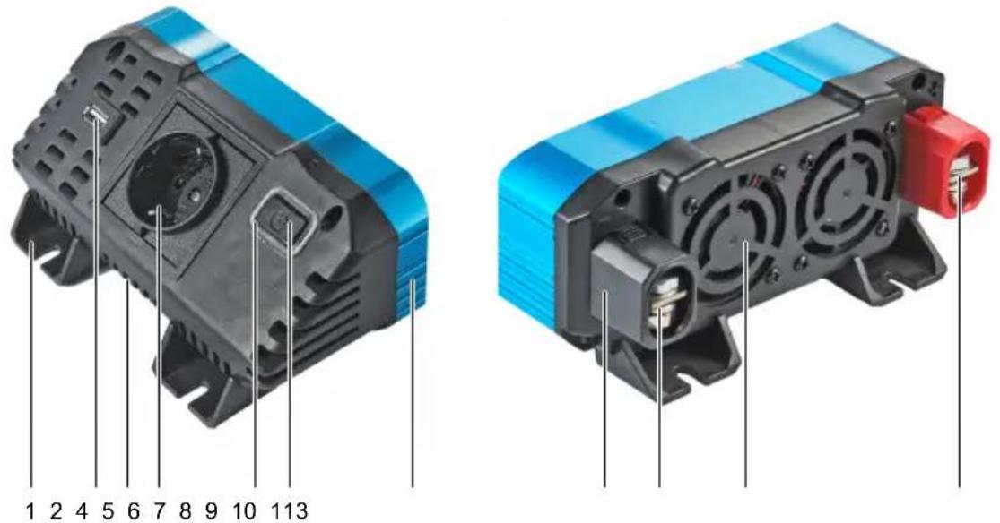
1 2 4 5 6 7 8 9 10 113
Images show item no. 2796911
| Part Component Description/Function | |||
| 1 Installation foot Secure the inverter to the installation surface. | |||
| 2 USB-A socket Connect 5 V/DC USB devices to power them. | |||
| 3 Ventilation slots Enable airflow to help cool internal components. | |||
| 4 Mains power socket | Connect | 230 V/AC mains appliances to power them. | |
| 5 Control LED | Indicates | the operational status:GREEN: Normal operationRED: Fault occurred (seeTroubleshooting [► 52]) | |
| 6 Power button | Switch the inverter on and off. | ||
| 7 Cooling fins | Dissipate | heat generated during operation. | |
| 8 Protective cap | Protect the terminals from accidental contact. | ||
| 9 Negative input terminal (-) | Connect | the negative terminal (-) of the input power source. | |
| 10 | Cooling fan | Cool the inverter during operation. | |
| 11 | Positive input terminal (+) | Connect the positive terminal (+) of the input power source. | |
8 Getting started
8.1 Selecting input power source
Select an input power source that satisfies the following:
- Rated voltage of input power source and inverter are identical.
– Example: 12 V/DC (input power source), 12 V/DC (inverter)
Input power source can supply the total required current ( C_T ) to start up and power all connected appliances. Consider start-up current requirements in your calculations. Calculate as follows: - Total required current (C_T) = Current of connected appliances (C_A) + 20% of C_A
- Example: C_A = 5A C_T = C_A + 0.2 × C_A = 5A + 0.2 × 5 = 6A
An appropriately sized fuse is installed between the input power source and the connection points to which you will connect the inverter. Do not connect the inverter directly to the input power source.
8.2 Selecting installation location
Select an installation location that satisfies the following:
The installation surface is dry and sturdy.
There is a distance of min. 5 cm on all sides for heat dissipation.
■ The inverter is easily accessible.
The inverter can be switched off quickly.
The inverter can be disconnected from the input power source quickly and safely.
■ Connected devices can be disconnected quickly and safely.
(Products with fan) the installation location is clear of loose objects (example: curtains) that could get sucked into the fan.
■ Vibrations at the installation location are minimal.
8.3 Selecting connection cables
Use the supplied connection cables if possible. If you use your own connection cables, select cables of suitable line cross-section. Contact a specialist if you lack the necessary knowledge to calculate the required line cross-section.
9 Installation
9.1 Installing the inverter
Preconditions:
√ You have selected an appropriate installation location.
- Use suitable washers and screws to fix the inverter at the feet to the installation surface.
10 Connection
10.1 Connecting input power source

WARNING
Touching live connectors can cause sparks
Risk of explosion of nearby rechargeable batteries.
- Do not rub electrical connectors against live connectors.
- Ensure ventilation around rechargeable batteries.
- Shield rechargeable batteries while making connections.
Connection diagram
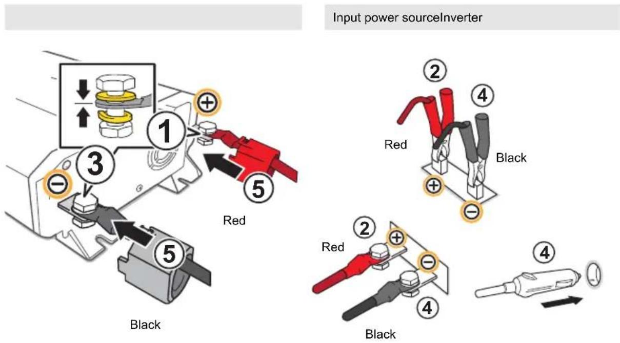
Note: the connection method for the input power source is dependent on the inverter model.
Making connections
Preconditions:
√ You have selected a suitable input power source.
√ The input power source is protected by a fuse.
- (If connecting to a vehicle) switch off the vehicle ignition.
- Remove the protective caps from the inverter input terminals.
- Guide the connection cables through the protective caps.
- Make the positive connection (+). Follow step (1) and then (2) of the connection diagram.
-
Make the negative connection (-). Follow step (3) and then (4) of the connection diagram. Do not connect to the car chassis!
-
(Cigarette lighter plug) Connect the plug to a cigarette lighter socket. Follow step (4) of the connection diagram.
- Secure cables with cable ties to prevent them from getting entangled.
- Check the connections. [▶ 49]
- Attach the protective caps to the inverter input terminals. Follow step (5) of the connection diagram.
→ The inverter is ready for operation.
10.2 Checking connections
Check the connections after making electrical connections to ensure safe operation. Make sure the following is satisfied and take corrective measures as necessary:
Cables are secured and cannot get caught by rotating parts (example: fan).
Cables do not touch surfaces that are hot or will become hot.
■ Connections are secure.
11 Operation
11.1 Powering mains appliances (230 V/AC)
The inverter can power mains appliances with different start-up power levels.
Important:
If the start-up power consumption of the mains appliance exceeds the peak output power of the inverter, the overload protection will be activated.
Requirements:
Make sure the mains appliance satisfies the below before connecting:
The rated power does not exceed the permanent output power of the inverter.
The start-up power does not exceed the peak output power of the inverter.
See "Technical data" for values.
Operating:
- (If possible) Switch the mains appliance off.
- Connect the mains appliance to the mains socket on the inverter.
- Push the power button to switch the inverter on and supply power to the connected appliance/device.
→ The control indicator is lit GREEN if no fault is detected.
→ The control indicator is lit RED if a fault is detected. See Troubleshooting [▶ 52]. - Start the mains appliance. If the inverter can power two mains appliances, start up the first appliance completely and only then start the second appliance.
- After use, push the power button to switch the inverter off.
11.2 Powering USB devices (5 V/DC)
- Connect the USB device to the USB socket on the inverter.
- Push the power button to switch the inverter on and supply power to the connected appliance/device.
→ The control indicator is lit GREEN if no fault is detected.
→ The control indicator is lit RED if a fault is detected. See Troubleshooting [▶ 52].
- After use, push the power button to switch the inverter off.
12 Protections
12.1 Reverse polarity protection
The reverse polarity protection protects the inverter from damage if the input polarity is swapped. If reverse polarity is detected, the inverter will not work.
12.2 Undervoltage protection
The undervoltage protection protects the input power source from damage.
See "Technical data" for values.
Notes:
For inverters connected to vehicles:
Starting the vehicle engine might trigger the undervoltage protection as the onboard voltage drops during the starting process.
The undervoltage protection operates in two stages:
| Stage Indications Recovery | ||
| Stage 1:Stage triggers if the first activation value is detected. | Control LED is lit GREEN.Alarm sounds-connected devices keep operating. | Push the power button to switch the inverter off.Connect another input power source.Push the power button to switch the inverter on. |
| Stage 2:Stage triggers if the second activation value is detected. | Control LED is lit RED.Alarm sounds-connected mains appliances stop operating-connected USB devices keep operating. | Push the power button to switch the inverter off.Connect another input power source.Push the power button to switch the inverter on. |
12.3 Overvoltage protection
The overvoltage protection protects the inverter from high input voltages.
See "Technical data" for values.
| Indications Recovery | |
| Indication sequence:1. Control LED turns RED.2. Alarm sounds.3. Inverter switches off. | 1. Push the power button to switch the inverter off.2. Connect a suitable input power source.3. Push the power button to switch the inverter on. |
12.4 Overload protection
The overload protection protects the inverter from damage if the total power consumption of connected devices exceeds the maximum power output of the inverter.
See "Technical data" for values.
| Indications Recovery | |
| Indication sequence:1. Alarm sounds.2. Inverter switches off. | 1. Disconnect the connected appliance/device. Do not connect and operate the appliance/device again.2. Press the power button to switch the inverter on. |
12.5 Overtemperature protection
The overtemperature protection protects the inverter from overheating. Excessive power consumption of connected devices and high ambient temperatures can cause the inverter to overheat.
See "Technical data" for values.
| Indications Recovery | |
| Indication sequence:1. Alarm sounds.2. Inverter switches off. | 1. Let the inverter cool down for 15 minutes.2. Check if the inverter is properly ventilated. If ambient temperatures are high, provide additional cooling (example: fan).3. Push the power button to switch the inverter on. |
13 Cleaning
Important:
- Do not use aggressive cleaning agents, rubbing alcohol or other chemical solutions. They damage the housing and can cause the product to malfunction.
-
Do not immerse the product in water.
-
Switch the product off.
- Let the product cool down to ambient temperature.
- Disconnect all connections.
- Clean the product with a dry, fibre-free cloth.
14 Troubleshooting
Power
| Problem Possible cause Suggested solution | |
| Inverter does not work. Connection cables connected with wrong polarity. | Connect connection cables with correct polarity. |
| Inverter does not output rated power. Connection cables are too long. Replace the connection cables by shorter ones. | |
Control LED and Alarm
| Problem Possible cause Suggested solution | ||
| ■ Control LED is lit GREEN.■ Alarm sounds. | Undervoltage protection "Stage 1" is activated. | See Undervoltage protection [▶ 50] |
| ■ Control LED is lit RED.■ Alarm sounds. | Undervoltage protection "Stage 2" is activated. | See Undervoltage protection [▶ 50] |
| Problem sequence:1. Control LED turns RED.2. Alarm sounds.3. Inverter switches off. | Overvoltage protection is activated. | See Overvoltage protection [▶ 50] |
| Problem sequence:1. Alarm sounds.2. Inverter switches off. | Overtemperature protection is activated. | See Overtemperature protection [▶ 51] |
| Overload protection is activated. See | Overload protection [▶ 51] | |
15 Disposal

This symbol must appear on any electrical and electronic equipment placed on the EU market. This symbol indicates that this device should not be disposed of as unsorted municipal waste at the end of its service life.
Owners of WEEE (Waste from Electrical and Electronic Equipment) shall dispose of it separately from unsorted municipal waste. Spent batteries and accumulators, which are not enclosed by the WEEE, as well as lamps that can be removed from the WEEE in a non-destructive manner, must be removed by end users from the WEEE in a non-destructive manner before it is handed over to a collection point.
Distributors of electrical and electronic equipment are legally obliged to provide free take-back of waste. Conrad provides the following return options free of charge (more details on our website):
in our Conrad offices
■ at the Conrad collection points
at the collection points of public waste management authorities or the collection points set up by manufacturers or distributors within the meaning of the ElektroG
End users are responsible for deleting personal data from the WEEE to be disposed of.
It should be noted that different obligations about the return or recycling of WEEE may apply in countries outside of Germany.
16 Technical data (2796905)
General
| Unit Value | ||
| Model MSW 150-12-G | ||
| Permanent output power W 150 | ||
| Peak output power W 300 | ||
| Efficiency (normal load) % >85 | ||
| Standby intake A <1 | ||
| Cooling Fan |
Input
| Unit Value | ||
| Required battery capacity (min.) Ah 30 | ||
| Rated input voltage V/DC 12 | ||
| Undervoltage alarm V/DC 10.5 ± 0.5 | ||
| Undervoltage deactivation V/DC 10 ± 0.5 | ||
| Overvoltage deactivation | V/DC 15 ± | 0.5 |
| Input connectors | Screw-type terminals |
Output (230 V/AC)
| Unit Value | ||
| Socket count 1 | ||
| Socket type Earth-protected, F-Type | ||
| Output voltage V/AC 230 | ||
| Output frequency Hz 50 | ||
| Signal output form Modified sine wave |
Output (USB)
| Unit Value | ||
| Socket count 1 | ||
| Socket type USB-A | ||
| Output voltage V/DC 5 | ||
| Max. output current A 2 | ||
| Max. output power W 10 |
Protections
| Unit Value | ||
| Fuse 1x 12 V/25 A, 6.3 x 32 mm (non-replaceable) | ||
| Reverse polarity protection Yes | ||
| Short-circuit protection Yes | ||
| Overload protection | Yes | |
| Overtemperature protection | Yes | |
Connection cables
| Unit Value | ||
| Cross-section | mm^2 | 1.3 |
| Length | m | 0.8 |
Environment
| Unit Value | ||
| Operating temperature | °C 0 to +60 | |
| Operating humidity | % | 20 - 85 |
| Storage temperature | °C 0 to +60 | |
| Storage humidity | % | 20 - 85 |
Others
| Unit Value | ||
| Dimensions (L x W x H) mm 222 x 107 x 73 | ||
| Weight kg 0.8 | ||
17 Technical data (2796906)
General
| Unit Value | ||
| Model MSW 300-12-G | ||
| Permanent output power W 300 | ||
| Peak output power W 600 | ||
| Efficiency (normal load) % >85 | ||
| Standby intake A <1 | ||
| Cooling Fan |
Input
| Unit Value | ||
| Required battery capacity (min.) Ah 60 | ||
| Rated input voltage V/DC 12 | ||
| Undervoltage alarm V/DC 10.5 ± 0.5 | ||
| Undervoltage deactivation V/DC 10 ± 0.5 | ||
| Overvoltage deactivation | V/DC 15 ± | 0.5 |
| Input connectors | Screw-type terminals |
Output (230 V/AC)
| Unit Value | ||
| Socket count | 1 | |
| Socket type | Earth-protected, F-Type | |
| Output voltage | V/AC | 230 |
| Output frequency | Hz 50 | |
| Signal output form | Modified sine wave |
Output (USB)
| Unit Value | ||
| Socket count | 1 | |
| Socket type | USB-A | |
| Output voltage | V/DC 5 | |
| Max. output current A 2 | ||
| Max. output power | W 10 |
Protections
| Unit Value | ||
| Fuse 1x 12 V/40 A, 6.3 x 32 mm (non-replaceable) | ||
| Reverse polarity protection Yes | ||
| Short-circuit protection Yes | ||
| Overload protection Yes | ||
| Overtemperature protection Yes | ||
Connection cables
| Unit Value | ||
| Cross-section mm^2 4 | ||
| Length m 0.6 |
Environment
| Unit Value | ||
| Operating temperature °C 0 to +60 | ||
| Operating humidity % 20 - 85 | ||
| Storage temperature °C 0 to +60 | ||
| Storage humidity % 20 - 85 |
Others
| Unit Value | ||
| Dimensions (L x W x H) | mm | 351 x 213 x 113 |
| Weight | kg | 2.2 |
18 Technical data (2796907)
General
| Unit Value | ||
| Model MSW 700-12-G | ||
| Permanent output power W 700 | ||
| Peak output power W 1400 | ||
| Efficiency (normal load) % >85 | ||
| Standby intake A <1 | ||
| Cooling Fan |
Input
| Unit Value | ||
| Required battery capacity (min.) Ah 140 | ||
| Rated input voltage V/DC 12 | ||
| Undervoltage alarm V/DC 10.5 ± 0.5 | ||
| Undervoltage deactivation V/DC 10 ± 0.5 | ||
| Overvoltage deactivation | V/DC 15 ± | 0.5 |
| Input connectors | Screw-type terminals |
Output (230 V/AC)
| Unit Value | ||
| Socket count | 1 | |
| Socket type | Earth-protected, F-Type | |
| Output voltage | V/AC | 230 |
| Output frequency | Hz 50 | |
| Signal output form | Modified sine wave |
Output (USB)
| Unit Value | ||
| Socket count | 1 | |
| Socket type | USB-A | |
| Output voltage | V/DC 5 | |
| Max. output current A 2 | ||
| Max. output power | W 10 |
Protections
| Unit Value | ||
| Fuse 2x 12 V/40 A, 6.3 x 32 mm (non-replaceable) | ||
| Reverse polarity protection Yes | ||
| Short-circuit protection Yes | ||
| Overload protection Yes | ||
| Overtemperature protection Yes | ||
Connection cables
| Unit Value | ||
| Cross-section mm^2 10 | ||
| Length m 0.6 |
Environment
| Unit Value | ||
| Operating temperature °C 0 to +60 | ||
| Operating humidity % 20 - 85 | ||
| Storage temperature °C 0 to +60 | ||
| Storage humidity % 20 - 85 |
Others
| Unit Value | ||
| Dimensions (L x W x H) | mm | 684 x 546 x 446 |
| Weight | kg | 2.2 |
19 Technical data (2796908)
General
| Unit Value | ||
| Model MSW 2000-12-G | ||
| Permanent output power W 2000 | ||
| Peak output power W 4000 | ||
| Efficiency (normal load) % >85 | ||
| Standby intake A <1 | ||
| Cooling Fan |
Input
| Unit Value | ||
| Required battery capacity (min.) Ah 400 | ||
| Rated input voltage V/DC 12 | ||
| Undervoltage alarm V/DC 10.5 ± 0.5 | ||
| Undervoltage deactivation V/DC 10 ± 0.5 | ||
| Overvoltage deactivation | V/DC 15 ± | 0.5 |
| Input connectors | Screw-type terminals |
Output (230 V/AC)
| Unit Value | ||
| Socket count | 2 | |
| Socket type | Earth-protected, F-Type | |
| Output voltage | V/AC | 230 |
| Output frequency | Hz 50 | |
| Signal output form | Modified sine wave |
Output (USB)
| Unit Value | ||
| Socket count | 1 | |
| Socket type | USB-A | |
| Output voltage | V/DC 5 | |
| Max. output current A 2 | ||
| Max. output power | W 10 |
Protections
| Unit Value | ||
| Fuse 8x 12 V/40 A, 6.3 x 32 mm (non-replaceable) | ||
| Reverse polarity protection Yes | ||
| Short-circuit protection Yes | ||
| Overload protection Yes | ||
| Overtemperature protection Yes | ||
Connection cables
| Unit Value | ||
| Cross-section mm^2 25 | ||
| Length m 0.6 |
Environment
| Unit Value | ||
| Operating temperature °C 0 to +60 | ||
| Operating humidity % 20 - 85 | ||
| Storage temperature °C 0 to +60 | ||
| Storage humidity % 20 - 85 |
Others
| Unit Value | ||
| Dimensions (L x W x H) | mm | 503 x 269 x 141 |
| Weight | kg | 5.8 |
20 Technical data (2796909)
General
| Unit Value | ||
| Model PSW 300-12-G | ||
| Permanent output power W 300 | ||
| Peak output power W 600 | ||
| Efficiency (normal load) % >85 | ||
| Standby intake A <1 | ||
| Cooling Fan |
Input
| Unit Value | ||
| Required battery capacity (min.) Ah 60 | ||
| Rated input voltage V/DC 12 | ||
| Undervoltage alarm V/DC 10.5 ± 0.5 | ||
| Undervoltage deactivation V/DC 10 ± 0.5 | ||
| Overvoltage deactivation | V/DC 15 ± | 0.5 |
| Input connectors | Screw-type terminals |
Output (230 V/AC)
| Unit Value | ||
| Socket count | 1 | |
| Socket type | Earth-protected, F-Type | |
| Output voltage | V/AC | 230 |
| Output frequency | Hz 50 | |
| Signal output form | Pure sine wave |
Output (USB)
| Unit Value | ||
| Socket count | 1 | |
| Socket type | USB-A | |
| Output voltage | V/DC 5 | |
| Max. output current A 2 | ||
| Max. output power | W 10 |
Protections
| Unit Value | ||
| Fuse 1x 12 V/35 A, 6.3 x 32 mm (non-replaceable) | ||
| Reverse polarity protection Yes | ||
| Short-circuit protection Yes | ||
| Overload protection Yes | ||
| Overtemperature protection Yes | ||
Connection cables
| Unit Value | ||
| Cross-section mm^2 4 | ||
| Length m 0.6 |
Environment
| Unit Value | ||
| Operating temperature °C 0 to +60 | ||
| Operating humidity % 20 - 85 | ||
| Storage temperature °C 0 to +60 | ||
| Storage humidity % 20 - 85 |
Others
| Unit Value | ||
| Dimensions (L x W x H) | mm | 232 x 107 x 73 |
| Weight | kg | 0.8 |
21 Technical data (2796910)
General
| Unit Value | ||
| Model PSW 1000-12-G | ||
| Permanent output power W 1000 | ||
| Peak output power W 2000 | ||
| Efficiency (normal load) % >85 | ||
| Standby intake A <1 | ||
| Cooling Fan |
Input
| Unit Value | ||
| Required battery capacity (min.) Ah 200 | ||
| Rated input voltage V/DC 12 | ||
| Undervoltage alarm V/DC 10.5 ± 0.5 | ||
| Undervoltage deactivation V/DC 10 ± 0.5 | ||
| Overvoltage deactivation | V/DC 15 ± | 0.5 |
| Input connectors | Screw-type terminals |
Output (230 V/AC)
| Unit Value | ||
| Socket count | 2 | |
| Socket type | Earth-protected, F-Type | |
| Output voltage | V/AC | 230 |
| Output frequency | Hz 50 | |
| Signal output form | Pure sine wave |
Output (USB)
| Unit Value | ||
| Socket count | 1 | |
| Socket type | USB-A | |
| Output voltage | V/DC 5 | |
| Max. output current A 2 | ||
| Max. output power | W 10 |
Protections
| Unit Value | ||
| Fuse 4x 12 V/35 A, 6.3 x 32 mm (non-replaceable) | ||
| Reverse polarity protection Yes | ||
| Short-circuit protection Yes | ||
| Overload protection Yes | ||
| Overtemperature protection Yes | ||
Connection cables
| Unit Value | ||
| Cross-section mm^2 10 | ||
| Length m 0.6 |
Environment
| Unit Value | ||
| Operating temperature °C 0 to +60 | ||
| Operating humidity % 20 - 85 | ||
| Storage temperature °C 0 to +60 | ||
| Storage humidity % 20 - 85 |
Others
| Unit Value | ||
| Dimensions (L x W x H) | mm | 414 x 213 x 113 |
| Weight | kg | 2.25 |
22 Technical data (2796911)
General
| Unit Value | ||
| Model MSW 1200-12-G | ||
| Permanent output power W 1200 | ||
| Peak output power W 2400 | ||
| Efficiency (normal load) % >85 | ||
| Standby intake A <1 | ||
| Cooling Fan |
Input
| Unit Value | ||
| Required battery capacity (min.) Ah 240 | ||
| Rated input voltage V/DC 12 | ||
| Undervoltage alarm V/DC 10.5 ± 0.5 | ||
| Undervoltage deactivation V/DC 10 ± 0.5 | ||
| Overvoltage deactivation | V/DC 15 ± | 0.5 |
| Input connectors | Screw-type terminals |
Output (230 V/AC)
| Unit Value | ||
| Socket count | 1 | |
| Socket type | Earth-protected, F-Type | |
| Output voltage | V/AC | 230 |
| Output frequency | Hz 50 | |
| Signal output form | Modified sine wave |
Output (USB)
| Unit Value | ||
| Socket count | 1 | |
| Socket type | USB-A | |
| Output voltage | V/DC 5 | |
| Max. output current A 2 | ||
| Max. output power | W 10 |
Protections
| Unit Value | ||
| Fuse 2x 12 V/40 A, 6.3 x 32 mm (non-replaceable) | ||
| Reverse polarity protection Yes | ||
| Short-circuit protection Yes | ||
| Overload protection Yes | ||
| Overtemperature protection Yes | ||
Connection cables
| Unit Value | ||
| Cross-section mm^2 10 | ||
| Length m 0.6 |
Environment
| Unit Value | ||
| Operating temperature °C 0 to +60 | ||
| Operating humidity % 20 - 85 | ||
| Storage temperature °C 0 to +60 | ||
| Storage humidity % 20 - 85 |
Others
| Unit Value | ||
| Dimensions (L x W x H) | mm | 357 x 175 x 73 |
| Weight | kg | 2.7 |
23 Technical data (2898080)
General
| Unit Value | ||
| Model MSW 3000-12-G | ||
| Permanent output power W 3000 | ||
| Peak output power W 6000 | ||
| Efficiency (normal load) % >85 | ||
| Standby intake A <1 | ||
| Cooling Fan |
Input
| Unit Value | ||
| Rated input voltage V/DC 12 | ||
| Undervoltage alarm V/DC 11 ± 0.5 | ||
| Undervoltage deactivation V/DC 10.5 ± 0.5 | ||
| Overvoltage deactivation V/DC 15 ± 0.5 | ||
| Input connectors Screw-type terminals |
Output (230 V/AC)
| Unit Value | ||
| Socket count | 2 | |
| Socket type | Earth-protected, F-Type | |
| Output voltage | V/AC | 230 |
| Output frequency | Hz | 50 |
| Signal output form | Modified sine wave |
Output (USB)
| Unit Value | ||
| Socket count | 1 | |
| Socket type | USB-A | |
| Output voltage | V/DC 5 | |
| Max. output current A 2 | ||
| Max. output power | W 10 |
Protections
| Unit Value | ||
| Fuse 12x 12 V/40 A, 6.3 x 32 mm (non-replaceable) | ||
| Reverse polarity protection Yes | ||
| Short-circuit protection Yes | ||
| Overload protection Yes | ||
| Overtemperature protection Yes | ||
Connection cables
| Unit Value | ||
| Cross-section mm^2 35 | ||
| Length mm 0.6 |
Environment
| Unit Value | ||
| Operating temperature °C 0 to +60 | ||
| Operating humidity % 20 - 85 | ||
| Storage temperature °C 0 to +60 | ||
| Storage humidity % 20 - 85 |
Others
| Unit Value | ||
| Dimensions (L x W x H) | mm 541 x 235 x 107 | |
| Weight | kg | 5.8 |
24 Technical data (2898081)
General
| Unit Value | ||
| Model PSW 1500-12-G | ||
| Permanent output power W 1500 | ||
| Peak output power W 3000 | ||
| Efficiency (normal load) % >85 | ||
| Standby intake A <1 | ||
| Cooling Fan |
Input
| Unit Value | ||
| Rated input voltage V/DC 12 | ||
| Undervoltage alarm V/DC 11 ± 0.5 | ||
| Undervoltage deactivation V/DC 10.5 ± 0.5 | ||
| Overvoltage deactivation V/DC 15 ± 0.5 | ||
| Input connectors Screw-type terminals |
Output (230 V/AC)
| Unit Value | ||
| Socket count | 2 | |
| Socket type | Earth-protected, F-Type | |
| Output voltage | V/AC | 230 |
| Output frequency | Hz | 50 |
| Signal output form | Pure sine wave |
Output (USB)
| Unit Value | ||
| Socket count | 1 | |
| Socket type | USB-A | |
| Output voltage | V/DC 5 | |
| Max. output current A 2 | ||
| Max. output power | W 10 |
Protections
| Unit Value | ||
| Fuse 6x 12 V/35 A, 6.3 x 32 mm (non-replaceable) | ||
| Reverse polarity protection Yes | ||
| Short-circuit protection Yes | ||
| Overload protection Yes | ||
| Overtemperature protection Yes | ||
Connection cables
| Unit Value | ||
| Cross-section mm^2 16 | ||
| Length mm 0.6 |
Environment
| Unit Value | ||
| Operating temperature °C 0 to +60 | ||
| Operating humidity % 20 - 85 | ||
| Storage temperature °C 0 to +60 | ||
| Storage humidity % 20 - 85 |
Others
| Unit Value | ||
| Dimensions (L x W x H) | mm 454 x 269 x 141 | |
| Weight | kg | 2.5 |
25 Technical data (2898082)
General
| Unit Value | ||
| Model PSW 2000-12-G | ||
| Permanent output power W 2000 | ||
| Peak output power W 4000 | ||
| Efficiency (normal load) % >85 | ||
| Standby intake A <1 | ||
| Cooling Fan |
Input
| Unit Value | ||
| Rated input voltage V/DC 12 | ||
| Undervoltage alarm V/DC 11 ± 0.5 | ||
| Undervoltage deactivation V/DC 10.5 ± 0.5 | ||
| Overvoltage deactivation V/DC 15 ± 0.5 | ||
| Input connectors Screw-type terminals |
Output (230 V/AC)
| Unit Value | ||
| Socket count | 2 | |
| Socket type | Earth-protected, F-Type | |
| Output voltage | V/AC | 230 |
| Output frequency | Hz | 50 |
| Signal output form | Pure sine wave |
Output (USB)
| Unit Value | ||
| Socket count | 1 | |
| Socket type | USB-A | |
| Output voltage | V/DC 5 | |
| Max. output current A 2 | ||
| Max. output power | W 10 |
Protections
| Unit Value | ||
| Fuse 8x 12 V/35 A, 6.3 x 32 mm (non-replaceable) | ||
| Reverse polarity protection Yes | ||
| Short-circuit protection Yes | ||
| Overload protection Yes | ||
| Overtemperature protection Yes | ||
Connection cables
| Unit Value | ||
| Cross-section mm^2 25 | ||
| Length mm 0.6 |
Environment
| Unit Value | ||
| Operating temperature °C 0 to +60 | ||
| Operating humidity % 20 - 85 | ||
| Storage temperature °C 0 to +60 | ||
| Storage humidity % 20 - 85 |
Others
| Unit Value | ||
| Dimensions (L x W x H) | mm 548 x 269 x 141 | |
| Weight | kg | 2.5 |
26 Technical data (2898083)
General
| Unit Value | ||
| Model PSW 3000-12-G | ||
| Permanent output power W 3000 | ||
| Peak output power W 6000 | ||
| Efficiency (normal load) % >85 | ||
| Standby intake A <1 | ||
| Cooling Fan |
Input
| Unit Value | ||
| Rated input voltage V/DC 12 | ||
| Undervoltage alarm V/DC 11 ± 0.5 | ||
| Undervoltage deactivation V/DC 10.5 ± 0.5 | ||
| Overvoltage deactivation V/DC 15 ± 0.5 | ||
| Input connectors Screw-type terminals |
Output (230 V/AC)
| Unit Value | ||
| Socket count | 2 | |
| Socket type | Earth-protected, F-Type | |
| Output voltage | V/AC | 230 |
| Output frequency | Hz | 50 |
| Signal output form | Pure sine wave |
Output (USB)
| Unit Value | ||
| Socket count | 1 | |
| Socket type | USB-A | |
| Output voltage | V/DC 5 | |
| Max. output current A 2 | ||
| Max. output power | W 10 |
Protections
| Unit Value | ||
| Fuse 12x 12 V/35 A, 6.3 x 32 mm (non-replaceable) | ||
| Reverse polarity protection Yes | ||
| Short-circuit protection Yes | ||
| Overload protection Yes | ||
| Overtemperature protection Yes | ||
Connection cables
| Unit Value | ||
| Cross-section mm^2 35 | ||
| Length mm 0.6 |
Environment
| Unit Value | ||
| Operating temperature °C 0 to +60 | ||
| Operating humidity % 20 - 85 | ||
| Storage temperature °C 0 to +60 | ||
| Storage humidity % 20 - 85 |
Others
| Unit Value | ||
| Dimensions (L x W x H) | mm 623 x 269 x 151 | |
| Weight | kg | 6.5 |

Copyright by Conrad Electronic SE *2796905-11_2898080-83_V1_0824_jh_mh_de 36028797924508683-1 I5/O1 en

This is a publication by Conrad Electronic SE, Klaus-Conrad-Str. 1, D-92240 Hirschau (www.conrad.com).
All rights including translation reserved. Reproduction by any method (e.g. photocopying, microfilming or the capture in electronic data processing systems) requires prior written approval from the editor. Reprinting, also in part, is prohibited. This publication reflects the technical status at the time of printing.
Copyright by Conrad Electronic SE *2796905-11_2898080-83_V1_0824_jh_mh_en 36028797924508683-2 I5/O1 en
- Power inverter
- Introduction
- Intended use
- Operating Instructions for download
- Delivery contents
- Description of symbols
- Safety instructions
- General
- Handling
- Site of setup - Location
- Site of setup - Installation surface
- Electrical connections
- Operation
- Cleaning and maintenance
- Getting started
- Selecting input power source
- Selecting installation location
- Selecting connection cables
- Installation
- Installing the inverter
- Connection
- Connecting input power source
- WARNING
- Touching live connectors can cause sparks
- Connection diagram
- Making connections
- Preconditions:
- Checking connections
- Operation
- Powering mains appliances (230 V/AC)
- Important:
- Requirements:
- Operating:
- Powering USB devices (5 V/DC)
- Protections
- Reverse polarity protection
- Undervoltage protection
- Notes:
- Overvoltage protection
- Overload protection
- Overtemperature protection
- Cleaning
- Troubleshooting
- Disposal
- Technical data (2796905)
- Technical data (2796906)
- Technical data (2796907)
- Technical data (2796908)
- Technical data (2796909)
- Technical data (2796910)
- Technical data (2796911)
- Technical data (2898080)
- Technical data (2898081)
- Technical data (2898082)
- Technical data (2898083)
Brand : VOLTCRAFT
Model : PSW 3000-12-G
Category : Uncategorized