
R4040S - Saw RIDGID - Free user manual and instructions
Find the device manual for free R4040S RIDGID in PDF.
| Product Type | Tile Saw |
| Brand | Ridgid |
| Model | R4040S |
| Wheel Diameter | 203 mm (8 in) |
| Arbor Size | 15.8 mm (5/8 in) |
| Rip Capacity | 610 mm (24 in) |
| Diagonal Cut Capacity | 457 mm (18 in) |
| Max. Cutting Depth | 70 mm (2-3/4 in) |
| Power Supply | 120 V~, 12 A, 60 Hz |
| No-Load Speed | 5,000 rpm |
| Sliding Table | Yes, with locking |
| Miter Guide | With stops at 0°, 22.5°, and 45° |
| Bevel Cut | From 0° to 45° |
| Laser System | Adjustable Laser Guide |
| Water Pump | Submersible with adjustable flow |
| Protection | Wheel guard and splash guard |
| Wrench Storage | Built-in compartment |
| Transport Wheels | Yes, with handle |
| Warranty | 3-year limited |
Frequently Asked Questions - R4040S RIDGID
User questions about R4040S RIDGID
0 question about this device. Answer the ones you know or ask your own.
Ask a new question about this device
Download the instructions for your Saw in PDF format for free! Find your manual R4040S - RIDGID and take your electronic device back in hand. On this page are published all the documents necessary for the use of your device. R4040S by RIDGID.
USER MANUAL R4040S RIDGID
RIDG ^
OPERATOR'S MANUAL
MANUEL D'UTILISATION
MANUAL DEL OPERADOR
8 in. TILE AND PAVER SAW WITH LASER
SCIE À CARREAUX ET PAVES SOUS EAU
DE 203 mm (8 po) AVEC LASER
SIERRA PARA LOSAS Y PAVIMENTO
DE 203 mm (8 pulg.) CON LÁSER
R4040

To register your RIDGID product, please visit: http://register.RIDGID.com Pour enregistrer votre produit de RIDGID, s'il vous plaît la visite: http://register.RIDGID.com Para registrar su producto de RIDGID, por favor visita: http://register.RIDGID.com
Your saw has been engineered and manufactured to our high standard for dependability, ease of operation, and operator safety. When properly cared for, it will give you years of rugged, trouble-free performance.

WARNING:
To reduce the risk of injury, the user must read and understand the operator's manual before using this product.
SAVE THIS MANUAL FOR FUTURE REFERENCE
■ Operation....17-24
■ Adjustments....25-28
Réglages / Ajustes
■ Maintenance....29-30
Entretien / Mantenimiento
■ Warranty ....31
Garantie / Garantía
■ Parts Ordering and Service....Back page
Commande de pièces et réparation / Pedidos de piezas y servicio
INTRODUCTION
This product has many features for making its use more pleasant and enjoyable. Safety, performance, and dependability have been given top priority in the design of this product making it easy to maintain and operate.
* * *
Read and understand all instructions. Failure to follow all instructions listed below, may result in electric shock, fire and/or serious personal injury.
READ ALL INSTRUCTIONS
- KNOW YOUR POWER TOOL. Read the operator's manual carefully. Learn the saw's applications and limitations as well as the specific potential hazards related to this tool.
■ GUARD AGAINST ELECTRICAL SHOCK BY PREVENTING BODY CONTACT WITH GROUNDED SURFACES. For example, pipes, radiators, ranges, refrigerator enclosures. - KEEP GUARDS IN PLACE and in good working order.
■ REMOVE ADJUSTING KEYS AND WRENCHES. Form habit of checking to see that keys and adjusting wrenches are removed from tool before turning it on. - KEEP WORK AREA CLEAN. Cluttered areas and benches invite accidents. DO NOT leave tools or pieces of tile on the saw while it is in operation.
■ DO NOT USE IN DANGEROUS ENVIRONMENTS. Do not use power tools in damp or wet locations or expose to rain. Keep the work area well lit. - KEEP CHILDREN AND VISITORS AWAY. All visitors should wear safety glasses and be kept a safe distance from work area. Do not let visitors contact tool or extension cord while operating.
■ MAKE WORKSHOP CHILDPROOF with padlocks and master switches, or by removing starter keys.
■ DON'T FORCE TOOL. It will do the job better and safer at the feed rate for which it was designed.
■ USE RIGHT TOOL. Don't force the tool or attachment to do a job it was not designed for. Don't use it for a purpose not intended.
■ USE THE PROPER EXTENSION CORD. Make sure your extension cord is in good condition. Use only a cord heavy enough to carry the current your product will draw. An undersized cord will cause a drop in line voltage resulting in loss of power and overheating. A wire gauge size (A.W.G.) of at least 14 is recommended for an extension cord 25 feet or less in length. If in doubt, use the next heavier gauge. The smaller the gauge number, the heavier the cord.
■ DRESS PROPERLY. Do not wear loose clothing, gloves, neckties, or jewelry. They can get caught and draw you into moving parts. Rubber gloves and nonskid footwear (rubber soled boots) are recommended when working outdoors. Also wear protective hair covering to contain long hair.
■ ALWAYS WEAR EYE PROTECTION WITH SIDE SHIELDS WHICH IS MARKED TO COMPLY WITH ANSI Z87.1 WHEN USING THIS PRODUCT.
■ SECURE WORK. Use clamps or a vise to hold work when practical, it is safer than using your hand and frees both hands to operate the tool.
■ DON'T OVERREACH. Keep proper footing and balance at all times.
■ MAINTAIN TOOLS WITH CARE. Keep tools sharp and clean for better and safer performance. Follow instructions for lubricating and changing accessories.
■ DISCONNECT TOOLS. When not in use, before servicing, or when changing attachments, wheels, bits, cutters, etc., all tools should be disconnected.
■ AVOID ACCIDENTAL STARTING. Be sure switch is off when plugging in any tool.
■ USE RECOMMENDED ACCESSORIES. Consult the operator's manual for recommended accessories. The use of improper accessories may risk injury.
■ NEVER STAND ON TOOL. Serious injury could occur if the tool is tipped or if the cutting tool is unintentionally contacted.
■ CHECK DAMAGED PARTS. Before further use of the tool, a guard or other part that is damaged should be carefully checked to determine that it will operate properly and perform its intended function. Check for alignment of moving parts, binding of moving parts, breakage of parts, mounting and any other conditions that may affect its operation. A guard or other part that is damaged must be properly repaired or replaced by an authorized service center to avoid risk of personal injury.
■ USE THE RIGHT DIRECTION OF FEED. Feed work into a wheel or cutter against the direction of rotation of wheel or cutter only.
■ NEVER LEAVE TOOL RUNNING UNATTENDED. TURN THE POWER OFF. Don't leave tool until it comes to a complete stop.
■ PROTECT YOUR LUNGS. Wear a face or dust mask if the cutting operation is dusty.
■ PROTECT YOUR HEARING. Wear hearing protection during extended periods of operation.
■ DO NOT ABUSE CORD. Never carry tool by the cord or yank it to disconnect from receptacle. Keep cord from heat, oil, and sharp edges.
■ ALWAYS USE AN OUTDOOR EXTENSION CORD MARKED "W-A" OR "W". These cords are rated for outdoor use and reduce the risk of electric shock.
■ ALWAYS KEEP THE WHEEL GUARD IN PLACE and in working order.
- KEEP HANDS AWAY FROM CUTTING AREA. Keep hands away from wheels. Do not reach underneath work or around or over the wheel while wheel is rotating. Do not attempt to remove cut material when wheel is moving.
■ WHEEL COASTS AFTER BEING TURNED OFF.
■ NEVER USE IN AN EXPLOSIVE ATMOSPHERE. Normal sparking of the motor could ignite fumes.
■ INSPECT TOOL CORDS PERIODICALLY. If damaged, have repaired by a qualified service technician at an authorized service facility. The conductor with insulation having an outer surface that is green with or without yellow stripes is the equipment-grounding conductor. If repair or replacement of the electric cord or plug is necessary, do not connect the equipment-grounding conductor to a live terminal. Repair or replace a damaged or worn cord immediately. Stay constantly aware of cord location and keep it well away from the rotating wheel.
■ INSPECT EXTENSION CORDS PERIODICALLY and replace if damaged.
■ GROUND ALL TOOLS. If tool is equipped with three-prong plug, it should be plugged into a three-hole electrical receptacle.
■ ONLY POWER THE TOOL WITH A GFCI (GROUND FAULT CIRCUIT INTERRUPTOR) PROTECTED OUTLET.
■ CHECK WITH A QUALIFIED ELECTRICIAN or service personnel if the grounding instructions are not completely understood or if in doubt as to whether the tool is properly grounded.
■ USE ONLY CORRECT ELECTRICAL DEVICES: 3-wire extension cords that have 3-prong grounding plugs and 3-pole receptacles that accept the tool's plug.
■ DO NOT MODIFY the plug provided. If it will not fit the outlet, have the proper outlet installed by a qualified electrician.
- KEEP TOOL DRY, CLEAN, AND FREE FROM OIL AND GREASE. Always use a clean cloth when cleaning. Never
use brake fluids, gasoline, petroleum-based products, or any solvents to clean tool.
■ STAY ALERT AND EXERCISE CONTROL. Watch what you are doing and use common sense. Do not operate tool when you are tired. Do not rush.
■ DO NOT USE TOOL IF SWITCH DOES NOT TURN IT ON AND OFF. Have defective switches replaced by an authorized service center.
■ USE ONLY CORRECT WHEELS. Do not use wheels with incorrect size holes. Never use washers or arbor nuts that are defective or incorrect. The maximum wheel capacity of your saw is 8 in. (203 mm).
■ BEFORE MAKING ACUT, BESURE ALL ADJUSTMENTS ARE SECURE.
■ NEVER TOUCH WHEEL or other moving parts during use.
■ NEVER START A TOOL WHEN ANY ROTATING COMPONENT IS IN CONTACT WITH THE WORKPIECE.
■ DO NOT OPERATE A TOOL WHILE UNDER THE INFLUENCE OF DRUGS, ALCOHOL, OR ANY MEDICATION.
■ WHEN SERVICING use only identical replacement parts. Use of any other parts may create a hazard or cause product damage.
■ USE ONLY RECOMMENDED ACCESSORIES listed in this manual or addendums. Use of accessories that are not listed may cause the risk of personal injury. Instructions for safe use of accessories are included with the accessory.
■ DOUBLE CHECK ALL SETUPS. Make sure wheel is tight and not making contact with saw or workpiece before connecting to power supply.
SPECIFIC SAFETY RULES
■ SECURE WORK firmly against the miter guide or fence.
■ NEVER stand or have any part of your body in line with the path of the wheel.
■ NEVER attempt to free a stalled wheel without first turning the saw OFF and disconnecting the saw from the power source.
■ IF THE POWER SUPPLY CORD IS DAMAGED, it must be replaced only by the manufacturer or by an authorized service center to avoid risk.
■ AVOID AWKWARD OPERATIONS AND HAND POSITIONS where a sudden slip could cause your hand to move into the cutting tool.
■ MAKE SURE THE WORK AREA HAS AMPLE LIGHTING to see the work and that no obstructions will interfere with safe operation BEFORE performing any work using the saw.
■ ALWAYS TURN OFF SAW before disconnecting it, to avoid accidental starting when reconnecting to power supply.
■ THIS TOOL should have the following markings:
a) Wear eye, hearing, and breathing protection.
b) Use wheel guard for every operation for which it can be used.
c) Disconnect saw before servicing, when changing cutting wheels, and cleaning.
d) Use tool only with smooth edge cutting wheels free of openings, grooves, and teeth.
e) Replace damaged cutting wheel before operating.
f) Do not fill water bath above water fill line.
■ SAVE THESE INSTRUCTIONS. Refer to them frequently and use to instruct other users. If you loan someone this tool, loan them these instructions too.
| The following signal words and meanings are intended to explain the levels of risk associated with this product. | ||
| SYMBOL | SIGNAL | MEANING |
 | DANGER: | Indicates a hazardous situation, which, if not avoided, will result in death or serious injury. |
 | WARNING: | Indicates a hazardous situation, which, if not avoided, could result in death or serious injury. |
 | CAUTION: | Indicates a hazardous situation, that, if not avoided, may result in minor or moderate injury. |
| NOTICE: | (Without Safety Alert Symbol) Indicates information considered important, but not related to a potential injury (e.g. messages relating to property damage). | |
| Some of the following symbols may be used on this product. Please study them and learn their meaning. Proper interpretation of these symbols will allow you to operate the product better and safer. SYMBOL NAME DESIGNATION/EXPLANATION | ||
 | Safety Alert Indicates a potential personal injury hazard. | |
 | Read Operator's Manual | To reduce the risk of injury, user must read and understand operator's manual before using this product. |
 | Eye, Ear, & Breathing Protection | Always wear eye protection with side shields marked to comply with ANSI Z87.1 along with hearing and breathing protection. |
 | Wet Conditions Alert Do not expose to rain or use in damp locations. | |
 | No Hands | Failure to keep your hands away from the wheel will result in serious personal injury. |
 | Electrocution Failure to properly ground can result in electrocution. | |
| V Volts Voltage | ||
| A Amperes Current | ||
| Hz Hertz Frequency (cycles per second) | ||
| min Minutes Time | ||
| ~ | Alternating Current Type of current | |
| n_0 | No-Load Speed | Rotational speed, at no load |
| .../min | Per Minute | Revolutions, strokes, surface speed, orbits etc., per minute |
EXTENSION CORDS
Use only 3-wire extension cords that have 3-prong grounding plugs and 3-pole receptacles that accept the tool's plug. When using a power tool at a considerable distance from the power source, use an extension cord heavy enough to carry the current that the tool will draw. An undersized extension cord will cause a drop in line voltage, resulting in a loss of power and causing the motor to overheat. Use the chart provided below to determine the minimum wire size required in an extension cord. Only round jacketed cords listed by Underwriter's Laboratories (UL) should be used.
**Ampere rating (on tool data plate)
0-2.0 2.1-3.4 3.5-5.0 5.1-7.0 7.1-12.0 12.1-16.0
| Cord Length | Wire Size (A.W.G.) | ||||
| 25' | 16 | 16 | 16 | 16 | 14 |
| 50' | 16 | 16 | 16 | 14 | 14 |
| 100' | 16 | 16 | 14 | 12 | 10 |
**Used on 12 gauge - 20 amp circuit. NOTE: AWG = American Wire Gauge
Always use an extension cord that is designed for outside use. This is indicated by the letters “W-A” or “W” on the cord’s jacket.
Before using an extension cord, inspect it for loose or exposed wires and cut or worn insulation.
Use only extension cords that are intended for outdoor use. These extension cords are identified by a marking "Acceptable for use with outdoor appliances; store indoors while not in use". Use only extension cords having an electrical rating not less than the rating of the product. Do not use damaged extension cords. Examine extension cord before using and replace if damaged. Do not abuse extension cords and do not yank on any cord to disconnect. Keep cord away from heat and sharp edges. Always disconnect the extension cord from the receptacle before disconnecting the product from the extension cord.

WARNING:
Keep the extension cord clear of the working area. Position the cord so that it will not get caught on lumber, tools or other obstructions while you are working with a power tool. Failure to do so can result in serious personal injury.

WARNING:
Check extension cords before each use. If damaged replace immediately. Never use tool with a damaged cord since touching the damaged area could cause electrical shock resulting in serious injury.
ELECTRICAL CONNECTION
This tool is powered by a precision built electric motor. It should be connected to a power supply that is 120 V, AC only (normal household current), 60 Hz. Do not operate this tool on direct current (DC). A substantial voltage drop will cause a loss of power and the motor will overheat. If the saw does not operate when plugged into an outlet, double check the power supply.
SPEED AND WIRING
The no-load speed of this tool is approximately 5,000 rpm. This speed is not constant and decreases under a load or with lower voltage. For voltage, the wiring in a shop is as important as the motor's horsepower rating. A line intended only for lights cannot properly carry a power tool motor. Wire that is heavy enough for a short distance will be too light for a greater distance. A line that can support one power tool may not be able to support two or three tools.
GROUNDING INSTRUCTIONS
See Figure 1.
This tool must be grounded. In the event of a malfunction or breakdown, grounding provides a path of least resistance for electric current to reduce the risk of electric shock. This tool is equipped with an electric cord having an equipment-grounding conductor and a grounding plug. The plug must be plugged into a matching outlet that is properly installed and grounded in accordance with all local codes and ordinances.
Do not modify the plug provided. If it will not fit the outlet, have the proper outlet installed by a qualified electrician.

WARNING:
Improper installation of the grounding plug can result in a risk of electric shock. When repair or replacement of the cord is required, do not connect the grounding wire to either flat blade terminal. The wire with insulation having an outer surface that is green with or without yellow stripes is the grounding wire.
Check with a qualified electrician or service personnel if the grounding instructions are not completely understood, or if in doubt as to whether the tool is properly grounded.
Repair or replace a damaged or worn cord immediately.
This product is for use on a nominal 120 volt circuit and has a grounding plug similar to the plug illustrated in figure 1. Only connect the product to an outlet having the same configuration as the plug. Do not use an adapter with this product.
Ground Fault Circuit Interrupter (GFCI) protection should be provided on the circuit(s) or outlet(s) to be used for the tile saw. Outlets are available having built-in GFCI protection and may be used for this measure of safety.
If the saw is used with an extension cord, ensure the connection of the tool's power cord and the extension cord are not on the ground.
If a protected outlet is not available, do not use the saw until an outlet can be changed or auxiliary protection can be obtained. These auxiliary protection devices are available at your local retailer.
POSITION OF THE TILE SAW
See Figure 2.
To avoid the possibility of the tool plug or outlet getting wet, position tile saw to one side of a wall-mounted outlet to prevent water from dripping onto the outlet or plug. The operator should arrange a "drip loop" in the cord connecting the saw to the outlet. The "drip loop" is that part of the cord below the level of the outlet, or the connector if an extension cord is used, to prevent water traveling along the cord and coming in contact with the outlet.
If the plug or outlet does get wet, DO NOT unplug the cord. Disconnect the fuse or circuit breaker that supplies power to the tool then unplug and examine for the presence of water in the outlet.

WARNING:
To reduce the risk of electrocution, keep all connections dry and off the ground. Do not touch the plug with wet hands.

Fig. 1


PRODUCT SPECIFICATIONS
Wheel Diameter....8 in.
Wheel Arbor....5/8 in.
Rip Capacity (Tile size) 24 in.
Diagonal Capacity (Tile size) ....18 in.
Maximum Depth of Cut....2-3/4 in.
Rating 120 V\~, 12 Amps, 60 Hz
No Load Speed 5,000 r/min. (RPM)

Fig. 3
KNOW YOUR TILE SAW
See Figure 3.
The safe use of this product requires an understanding of the information on the tool and in this operator's manual as well as a knowledge of the project you are attempting. Before use of this product, familiarize yourself with all operating features and safety rules.
8 in. TILE CUTTING WHEEL - An 8 in. tile cutting wheel is included with your saw.

WARNING:
Do not use wheels rated less than the speed of this tool. Failure to heed this warning could result in personal injury.
BEVEL LOCK KNOB - The bevel lock knob securely locks the saw head at any bevel angle between 0° and 45°. It is recommended that you only make bevel cuts at 0°, 22.5°, and 45° angles.

WARNING:
Making bevel cuts at angles other than 0^ , 22.5^ , and 45^ angles could cause the cutting wheel to come in contact with the sliding table resulting in damage to the unit and/or possible serious injury.
ADJUSTABLE LASER ALIGNMENT SYSTEM - For more accurate cuts, a laser guide is included with the tile saw. When used properly, the laser guide makes accurate, precision cutting simple and easy. Simply push the button to turn the laser on or off.
MITER GUIDE - The easy-to-read indicator on the miter guide shows the exact angle for a miter cut with detents at 0^ , 22.5^ , and 45^ .
ON/OFF SWITCH - This saw has an easy access power switch located on the saw arm. To lock the switch, install a padlock (not included) through the hole in the switch trigger. When the lock is installed and locked, the switch is inoperable. Store the padlock key in another location.
SLIDING TABLE - The sliding table allows the user to slide the workpiece into the cutting wheel for accurate cuts.
SPLASH GUARD ASSEMBLY WITH TOOLESS REMOVABLE SIDE GUARD - The splash guard helps contain spray and mist.
SUBMERSIBLE PUMP - The submersible pump (not shown) provides water to the cutting wheel.
WATER TRAY EXTENSION - When cutting larger tile, the extension keeps work area cleaner and drier.
WRENCH STORAGE - The tile saw has a convenient storage area specifically designed for wrenches.
TOOLS NEEDED
The following tools (not included or drawn to scale) are needed for assembly and alignment:

Fig. 4
The following items are included with your tile saw:

Fig. 5
A - Motor head assembly....1
B - Hex key (6 mm)....1
C - Wheel wrench....1
D - Arbor nut....1
E - Cutting wheel ....1
F - Inner washer....1
G - Outer washer....1
H- Miter guide ....1
I - Sliding table....1
J - Frame ....1
K - Water tray ....1
L - Water filter ....1
M- Cap screw 4
N - Water pump....1
O - Screw....1
P - Washer....1
Q - Rear splash guard ....1
R - Side splash guard....1
S - Water tray extension....1
T - Hex key (2.5 mm)....1
UNPACKING
See Figure 5.
This product requires assembly.
■ Carefully lift the parts from the carton and place on a level work surface.
NOTE: Many of the Loose Parts are stored in the water reservoir.

WARNING:
Do not use this product if any parts on the Loose Parts list are already assembled to your product when you unpack it. Parts on this list are not assembled to the product by the manufacturer and require customer installation. Use of a product that may have been improperly assembled could result in serious personal injury.
■ Inspect the tool carefully to make sure no breakage or damage occurred during shipping.
■ Do not discard the packing material until you have carefully inspected and satisfactorily operated the tool.
■ The saw is factory set for accurate cutting. After assembling it, check for accuracy. If shipping has influenced the settings, refer to specific procedures explained in this manual.
■ If any parts are damaged or missing, please call 1-866-539-1710 for assistance.

WARNING:
If any parts are damaged or missing do not operate this tool until the parts are replaced. Use of this product with damaged or missing parts could result in serious personal injury.

WARNING:
Do not attempt to modify this tool or create accessories not recommended for use with this tool. Any such alteration or modification is misuse and could result in a hazardous condition leading to possible serious personal injury.

WARNING:
Do not connect to power supply until assembly is complete. Failure to comply could result in accidental starting and possible serious personal injury.
INSTALLING MOTOR HEAD ASSEMBLY TO FRAME
See Figure 6.
■ Align the holes in the motor head assembly with the holes on the frame.
■ Lower the motor head assembly onto the posts.
- Thread socket head screws through motor head assembly and into holes on frame.
■ Tighten screws using the 6 mm hex key (provided).
NOTE: Wrench storage is located in the back of the motor head assembly.
■ Set motor head and frame assembly aside.

Fig. 6
INSTALLING WATER FILTER AND WATER PUMP
See Figures 7 - 9.
The water pump recirculates water from the tray to the cutting wheel.
- Locate filter slots and pump well in water tray. Pump well is marked, "pump well."
■ Slide filter into filter slots, as shown. - Locate the "Max/Min" water flow selector on the pump. For best performance, start with the flow to "Max" to control the flow of water over the wheel.
NOTE: Water flow can be adjusted during use by removing the filter, reaching into water well and turning flow selector on pump. Reinsert filter.
■ Place water pump into pump well.

Fig. 7
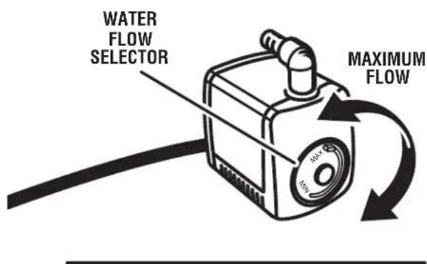

Fig. 8
INSTALLING WATER TRAY
See Figure 8 - 9.
■ Place the water tray, with the pump and filter in place, on a sturdy flat surface or on level ground.
■ Attach the water hose to the pump elbow.
■ Carefully lift the motor head and water tray frame assembly over the water tray, as shown.
■ Tilt the water tray frame and insert heavy duty tab into the bar slot on water tray.
- Secure the water tray frame in place with latches on front of the water tray.
■ Connect the pump power cord to the motor head power cord. Check that the rubber boot is pulled over cord connection to help keep water off the plug.
NOTE: The pump turns on when the motor is turned on. Let the cutting wheel build up to full speed and wait for the wheel to get wet before moving the material into the wheel.
■ Rest power cord and water hose in the notches provided on the water tray.

Fig. 9
INSTALLING THE SLIDING TABLE
See Figure 10.
To install the sliding table:
- Grasp the table firmly and set the rollers on the front of rails.
■ Holding the table parallel with the frame, push the table toward the back of the saw.
■ When the table lock lever reaches the stop on the front rail on the right hand side of the frame, pull the lever out and hold it out until the lock has passed the stop. Release the lever.
■ Slide the table along the rails until the final rollers engage the rails.
To lock sliding table:
■ Pull the table lock lever out and turn 90° counterclockwise.
■ Release the lever.
NOTE: When the sliding table is installed, and you push the table, it will "click" into place. This is the table lock lever snapping into a hole in the frame locking the table in place.
To unlock the sliding table:
■ Pull the table lock lever out and turn 90° clockwise.
TILE CUTTING WHEEL
For maximum performance and safety, it is recommended that you use the 8 in. cutting wheel provided with your saw. Additional cutting wheels of the same high quality are available at your local dealer.

WARNING:
Do not use cutting wheels rated less than the no load speed of this tool. Failure to heed this warning could result in personal injury. Do not use wheel with cracks, gaps, or teeth.
INSTALLING THE CUTTING WHEEL
See Figure 11.

WARNING:
A 8 in. tile cutting wheel is the maximum wheel capacity of the saw. Never use a wheel that is too thick to allow wheel washer to engage with the flats on the arbor. Larger wheels will come in contact with the splash hood, while thicker wheels will prevent the wheel bolt from securing the wheel on the arbor. Either of these situations could result in a serious accident and can cause serious personal injury.
■ Unplug the saw.
■ Lock table in front position.
■ Loosen wheel guard knob by turning counterclockwise and open the cutting wheel guard.

Fig. 10

■ Place the wheel wrench on the arbor nut then slide the 6 mm hex wrench into the arbor.
■ Holding the hex wrench firmly to prevent movement, turn the wheel wrench counterclockwise to loosen.
■ Remove the arbor nut and outer washer, leaving the inner washer on the arbor.

WARNING:
If inner washer has been removed, replace it before placing wheel on arbor. Failure to do so could cause an accident since the wheel will not tighten properly. Never use wheels that have openings, grooves, or teeth on this tool.
■ Place the cutting wheel onto arbor with the arrows on wheel going in the counterclockwise direction.
NOTE: Two water nozzles come installed on this product. Be sure to install cutting wheel so that there is a water nozzle on each side of cutting wheel with water ports facing the cutting wheel. The outer water nozzle can be easily removed for installation of cutting wheel. Check that outer nozzle outlet hole has been reattached with water port facing toward the cutting wheel.
- Replace the outer washer. The double "D" flats on the washers align with the flats on the arbor.
■ Replace the arbor nut on the arbor. Using wheel wrench and arbor wrench, tighten arbor nut securely.
INSTALLING SPLASH GUARD ASSEMBLY
See Figures 12 - 14.
The splash guard on this saw is a two-part assembly.
Attaching rear splash guard:
■ Line up rear splash guard holes with screw hole and post on back of cutting wheel guard, as shown.
■ Insert screw through washer and splash guard then thread into screw hole.
■ Tighten securely. Be careful not to overtighten.
Attaching side splash guard:
■ Install side splash guard over the rear splash guard.
■ Insert post, located on side of cutting wheel guard, through hole in side flap of guard.
■ Settle splash guard grooves over ridges in cutting wheel guard.
■ Repeat with other side.
■ After assembly is complete, pull rear splash guard outward so flaps rest over side splash guard.

Fig. 13
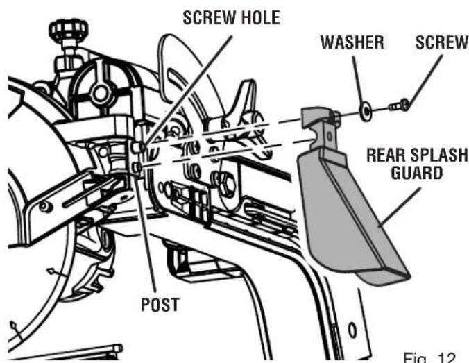
Fig. 12

Fig. 14
INSTALLING WATER TRAY EXTENSDN
See Figure 15.
■ Standing at the back of the saw, hold the water tray extension with the tray tabs toward the slots.
■ Tilt the tray and slip the tray tabs between the frame top and frame bottom. Tray should be over pump power cord and water hose.
■ Once the extension slides into place, lower until the tray tabs fit into the holes under frame.
INSTALLING THE MITER GUIDE
See Figure 16.
The miter guide can be used from both the left and right side of the cutting wheel.
■ Place the slot on the underside of the miter guide on the sliding table fence.
■ Lock the miter guide securely to the table by turning the miter guide knob clockwise.
To adjust angles:
■ Loosen the miter guide knob.
■ Set to the desired angle by moving the guide left or right.
■ Tighten the knob securely.
FILLING/CHANGING THE WATER RESERVOIR
See Figure 17.
■ Install drain cap.
Fill the water reservoir with clean tap water to the fill line. Do not fill past the "maximum" line on the tray.
To change reservoir water:
■ Unplug the saw.
■ Remove the drain cap and empty waste water into a bucket. Do not allow the water to splash onto the ground or around the machine.
■ Rinse the water reservoir thoroughly.
■ Discard the waste water in accordance with local regulations.
■ Replace the drain cap and refill tray with clean water.
NOTE: Drain fits standard size garden hose.
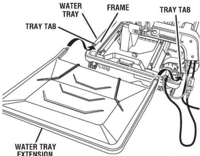
Fig. 15
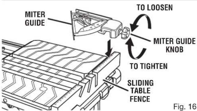
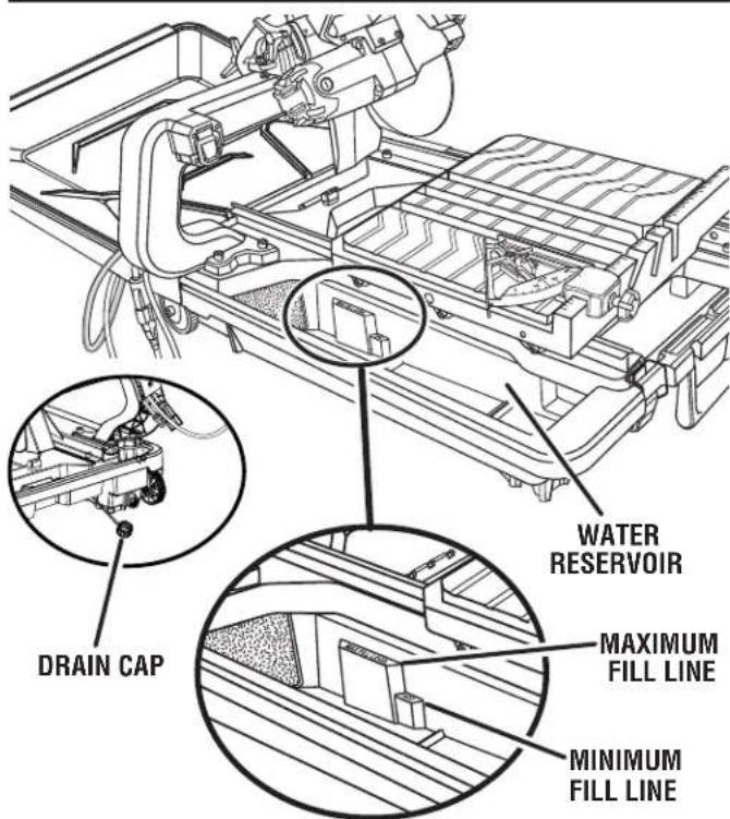
Fig. 17
TRANSPORTING THE TILE SAW
See Figure 18.
■ Lock the sliding table.
■ Remove the water tray extension.
■ Be sure the hoses and cords do not drag on the ground.
■ Saw is easily moved, using pull handle and wheels.

natural_image
Line drawing of a person walking with luggage, no text or symbols presentFig. 18
OPERATION

WARNING:
Do not allow familiarity with tools to make you careless. Remember that a careless fraction of a second is sufficient to inflict serious injury.

WARNING:
Always wear eye protection with side shields marked to comply with ANSI Z87.1 along with hearing and breathing protection. Failure to do so could result in objects being thrown into your eyes, resulting in possible serious injury.

WARNING:
Do not use any attachments or accessories not recommended by the manufacturer of this tool. The use of attachments or accessories not recommended can result in serious personal injury.
APPLICATIONS
This saw is designed to cut man-made tile, pavers, stone tile, and pavers up to 4 in maximum.
You may use this tool for the purposes listed below:
■ Straight line cutting operations such as cross cutting, mitering, ripping, plunging, and beveling
■ Cutting garden stone
ON/OFF SWITCH
See Figure 19.
To turn your saw on:
■ Lift the switch to turn on.
To turn your saw off:
■ Press the switch down to turn off.
To lock your saw:
■ With the saw turned off, install a padlock (not included) through the hole in the switch.

WARNING:
In the event of a power failure or when the tool is not in use, turn the on/off switch off. This action will prevent the tool from accidentally starting when power returns.

WARNING:
ALWAYS make sure your workpiece is not in contact with the cutting wheel before operating the switch to start the tool. Failure to heed this warning can cause the workpiece to be kicked back toward the operator and result in serious personal injury.

WARNING:
To reduce the risk of accidental starting, ALWAYS make sure the on/off switch is in the off position before plugging tool into the power source.
LOCKING/UNLOCKING THE MOTOR HEAD FOR PLUNGE CUTS
See Figure 20.
To unlock and raise the motor head:
■ Firmly grasp the "D" handle and apply downward pressure while at the same time turning the motor head lock knob counterclockwise.
■ Slowly raise the motor head.
To lock the motor head:
■ Firmly grasp the "D" handle and apply downward pressure while at the same time turning the motor head lock knob clockwise to lock.
NOTE: For all through cuts, place the saw in the locked position.

Fig. 19

MOTOR HEAD
Fig. 20
MAKING CUTS
Always draw the line to be cut on the tile using a marker or grease pencil. If the tile is shiny and hard-to-mark, place masking tape on the tile and mark the tape.
A common problem when cutting tile is straying from the marked line. Once you've strayed from the mark, you can not force the wheel back to the line by twisting the tile. Instead, back up and recut the tile slicing off a small amount of tile until the wheel is back on track.
To avoid this problem, use the miter guide whenever possible.
Another problem is cutting difficult material. To prevent chipping of the material at the end of the cut, use a plunge cut.
NOTE: A more shallow blade adjustment may help minimize chipping, see the Depth stop adjustments section.
Clean the saw table and miter guide frequently during use. Debris from the cut material can interfere with tool function.

DANGER:
Laser radiation. Avoid direct eye contact with light source.

WARNING:
Use of controls or adjustments or performance of procedures other than those specified herein may result in hazardous radiation exposure.
USING THE LASER GUIDE
See Figure 21.
Using a straight edge or square, draw a mark on the tile with a marker or grease pencil. Turn the laser on and off by pressing the laser guide switch located on the side of the "D" handle. When the laser is turned on it will generate a red line on the work surface. This line will let you see your mark and the laser guide line at the same time, and will assist you in lining up the mark for more accurate cutting of the tile.
NOTE: Laser may be difficult to see in bright sunlight.
With the wheel in the cutting position, move the tile until the mark and the laser line are aligned.
Make several practice cuts on different styles and thickness of material. Repeat the steps as necessary.
Removing Your Mark:
Position the tile so that the laser line is near the left edge of your mark in order to remove the mark.
To Cut Your Mark:
Position the tile so that the laser line is near or over your mark in order to cut the mark.
To Leave Your Mark:
Position the tile so that the laser line is near the right edge of your mark in order to leave the mark.
After you have become familiar with using the laser guide, you will be able to remove, cut, or leave your mark on the work surface. Practice will teach you the correct position for aligning your mark with the laser line.
To adjust the position of the laser guide line, refer to the Adjustments section later in this manual.

Fig. 21
TO MAKE A CROSS CUT / RIP CUT
See Figure 22.
Cross/rip cuts are straight 90° cuts. The material is fed into the cut at a 90° angle to the wheel, and the wheel is vertical.
■ Using a straight edge or square, draw a line on the tile with a marker or grease pencil.
■ Set the miter guide to 0^ for right side or 90^ for left side use. Tighten the lock knob, and lock in place.
■ Make sure miter guide is not in the cut path.
■ Place the material on the table and firmly against the miter guide and fence.
■ Make sure the material is clear of the cutting wheel before turning on the saw.
■ Flip the on/off switch to the on position.
■ Let the cutting wheel build up to full speed and wait for the wheel to get wet before moving the material into the wheel.
■ Hold the material firmly against the miter guide and fence and slowly feed the material into the cutting wheel.
■ When the cut is made, turn the saw off. Wait for the cutting wheel to come to a complete stop before removing any part of the material.
TO MAKE A DIAGONAL CUT
See Figure 23.
Diagonal cuts are also referred to as "long point-to-long point cuts".
■ Using a straight edge or square, draw a line on the tile with a marker or grease pencil.
■ Set the miter guide to 0^ for right side or 90^ for left side use. Tighten the lock knob, and lock in place.
■ Make sure miter guide is not in the cut path.
■ Place the material on the table and firmly against the miter guide and fence.
■ Make sure the material is clear of the cutting wheel before turning on the saw.
■ Flip the on/off switch to the on position.
■ Let the cutting wheel build up to full speed and wait for the wheel to get wet before moving the material into the wheel.
■ Hold the material firmly against the miter guide and fence and slowly feed the material into the cutting wheel.
■ When the cut is made, turn the saw off. Wait for the cutting wheel to come to a complete stop before removing any part of the material.
CROSS CUT / RIP CUT

Fig. 22

Fig. 23
TO MAKE A MITER CUT
See Figure 24.
Miter cuts are used for cutting outside and inside corners on material, at any angle to the wheel other than 90°. Miter cuts tend to "creep" during cutting. This can be controlled by holding the workpiece securely against the miter guide.
■ Using a marker or grease pencil, mark the area to be cut on material.
■ Set the miter guide to the desired setting, lock in place, and tighten the lock knob.
■ Make sure miter guide is not in the cut path.
■ Place the material on the table and firmly against the miter guide and fence.
■ Make sure the material is clear of the cutting wheel before turning on the saw.
■ Flip the on/off switch to the on position.
■ Let the cutting wheel build up to full speed and wait for the wheel to get wet before moving the material into the wheel.
■ Hold the material firmly against the miter guide and fence and slowly feed the material into the cutting wheel.
■ When the cut is made, turn the saw off. Wait for the cutting wheel to come to a complete stop before removing any part of the material.
TO MAKE AN L-CUT
See Figure 25.
L-cuts are cuts that remove a piece of tile to fit in a corner, around a cabinet, or a piece of molding and are made by two separate cuts.
NOTE: Only over cut on the bottom or underside of the material being cut.
■ Using a marker or grease pencil, mark the area to be cut on both sides of the material.
■ Set the miter guide to the desired setting; lock in place.
■ Make sure miter guide is not in the cut path.
■ Place the material on the table and firmly against the miter guide and fence.
■ Make sure the material is clear of the cutting wheel before turning on the saw.
■ Flip the on/off switch to the on position.
■ Let the cutting wheel build up to full speed and wait for the wheel to get wet before moving the material into the wheel.
■ Hold the material firmly against the miter guide and fence and slowly feed the material into the cutting wheel.
■ Make the cut far enough into the material without over cutting other line.
■ When the cut is made, turn the saw off. Wait for the cutting wheel to come to a complete stop before removing any part of the material.
■ Turn the material over and make the cut along uncut mark. This time, carefully over cut the other line and the cut piece should separate from the rest of the material.
■ When the second cut is made, turn the saw off. Wait for the cutting wheel to come to a complete stop before removing any part of the material.
MITER CUT

natural_image
Technical line drawing of a mechanical assembly with rollers, gears, and a base plate (no text or symbols)Fig. 24
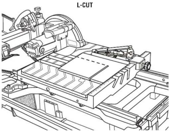
Fig. 25
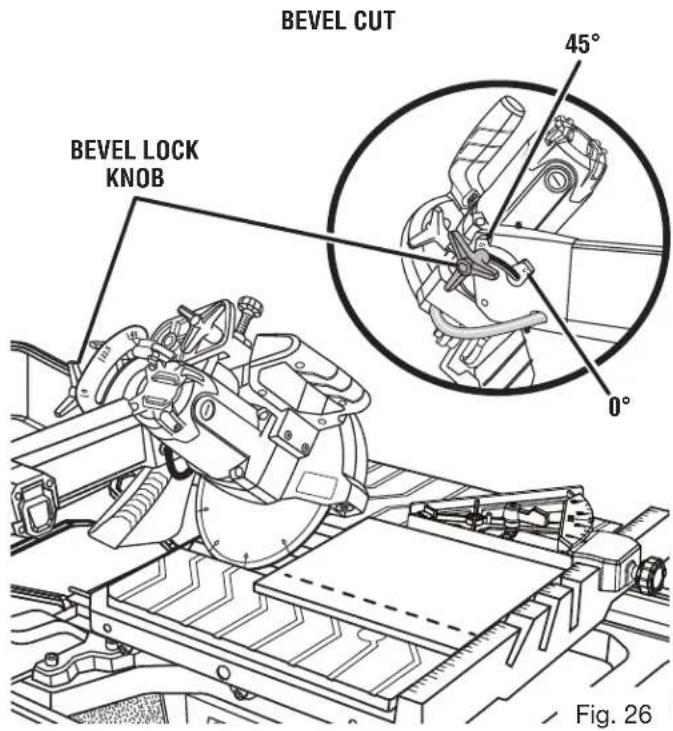
TO MAKE A BEVEL CUT
See Figure 26.
Bevel cuts are made by feeding the material into the cutting wheel with the motor head at an angle. It is recommended that you only make cuts at 0^ , 22.5^ and 45^ .

WARNING:
Making cuts at angles other than 0^ , 22.5^ and 45^ angles could cause the cutting wheel to come in contact with the sliding table resulting in damage to the unit and/or possible serious injury.
■ Using a straight edge or square, draw a line on the tile with a marker or grease pencil.
■ Slide the saw table to the front of the water tray before tilting the saw head.
■ Loosen the bevel lock knob.
■ Set the saw arm to a 22.5^ or 45^ angle and tighten the bevel knob.
■ Place the miter guide on the table the desired distance from the wheel and lock in place.
■ Make sure miter guide is not in the cut path.
■ Place the material on the table and firmly against the miter guide and fence.
■ Make sure the material is clear of the cutting wheel before turning on the saw.
■ Turn the on/off switch to the on position.
■ Let the cutting wheel build up to full speed and wait for the wheel to get wet before moving the material into the wheel.
■ Hold the material firmly against the miter guide and fence and slowly feed the material into the cutting wheel.
■ When the cut is made, turn the saw off. Wait for the cutting wheel to come to a complete stop before removing any part of the material.
Plunge cuts are made by positioning the material directly underneath the cutting wheel and lowering the wheel onto the workpiece. This allows pieces to be cut from the center of the material.
■ Using a marker or grease pencil, mark the area to be cut on material.
■ Loosen the lock knob on the side of the motor head and position the motor head upward to its maximum height.
■ Place the miter guide on the table the desired distance from the wheel and lock in place.
■ Turn the on/off switch to the on position.
■ Let the cutting wheel build up to full speed and wait for the wheel to get wet before moving the material into the wheel.
■ Hold the motor head firmly by the handle.
■ Move the material into the desired position for cutting.
■ Slowly lower the motor head into the material to make the cut.
■ Raise the motor head.
■ Turn the on/off switch to the off position.
■ Slide the table away from the motor head and position the work material for the next cut.
PLUNGE CUT

natural_image
Technical line drawing of a mechanical assembly with no visible text or symbolsMAKING GARDEN PAVER CUTS
See Figures 28 - 31.
Garden pavers require special cuts to make curves and corners in walls, patios, and other landscaping features.
To cut paver shorter:
■ Measure paver to determine how much material needs to be removed.
■ Using a marker or grease pencil, make two marks, marking all the way around the paver.
■ Place the material on the table and firmly against the fence.
NOTE: It may be necessary to remove side splash guard to make room for paver cut.
■ Make sure the material is clear of the cutting wheel before turning on the saw.
■ Turn the on/off switch to the on position.
■ Let the cutting wheel build up to full speed and wait for the wheel to get wet before moving the material into the wheel.
■ Hold the material firmly against the miter guide and fence and feed the material into the cutting wheel.
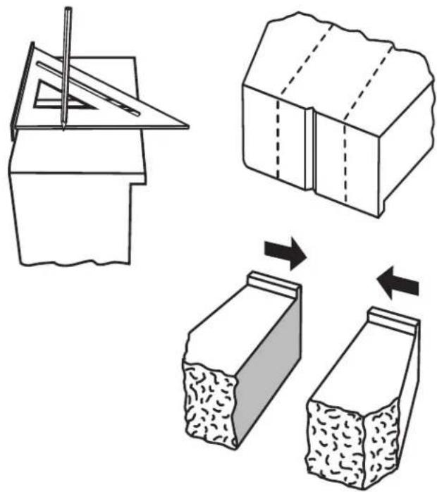
Fig. 28
■ When the cut is made, turn the saw off. Wait for the cutting wheel to come to a complete stop before removing any part of the material.
■ Move the sliding table away from the motor head and turn paver over to make through cut.

Fig. 29

Fig. 30
To make paver for corners:
■ Measure paver and landscaping feature to determine how much material needs to be removed and how much of an angle is required for wall corner.
■ Using grease pencil and square, draw a mark from center of brick to corner, marking all the way around the paver.
■ Place the material on the table and firmly against the fence.
■ Make sure the material is clear of the cutting wheel before turning on the saw.
■ Turn the on/off switch to the on position.
■ Let the cutting wheel build up to full speed and wait for the wheel to get wet before moving the material into the wheel.
■ Hold the material firmly against the miter guide and fence and feed the material into the cutting wheel.
■ When the cut is made, turn the saw off. Wait for the cutting wheel to come to a complete stop before removing any part of the material.
■ Move the sliding table away from the motor head and turn paver over to make through cut.
If stacking paver, knock off pavers' drop edge, turn paver over and lay paver.

Fig. 31

WARNING:
Before performing any adjustment, make sure the tool is unplugged from the power supply and the switch is in the OFF position. Failure to heed this warning could result in serious personal injury.
The saw has been adjusted at the factory for making very accurate cuts. However, some of the components might have been jarred out of alignment during shipping. Also, over a period of time, readjustment will probably become necessary due to wear, and/or transport.
Do not start any adjustments until you have checked with a square and made test cuts to be sure adjustments are needed.
TO SQUARE THE CUTTING WHEEL TO THE TABLE
See Figures 32 - 34.
Do not loosen any screws for this adjustment until you have checked with a square and made test cuts to be sure adjustments are necessary. Once the screws are loosened, these items must be reset.
■ Unplug the saw.
■ Using the hex key, loosen cap bolts on the left rail.
■ Place a framing square against the fence and the flat part of the wheel.
■ Make adjustments and tighten bolts securely.
■ Move sliding table through full range of travel, to check for square. Make adjustments again, if necessary.
■ Check distance of rails at the front and the rear. Distance between inside rails should be 12-7/16 in.
■ Visually check that blade is centered in 0^ slot.
■ After all necessary rail adjustments have been made tighten the hex bolts securely.


Fig. 33

Fig. 34
TO ADJUST SLIDING TABLE
See Figures 35 - 38.
If the sliding table doesn't roll smoothly on the rails or wiggles side to side, adjustments are required. The wheels on the sliding table should gently touch rails and roll smoothly through the full range of travel.
To adjust the center upper cam roller:
The left side upper rollers sit on the track. They have a groove down the middle of each roller. If the upper rollers are not parallel and/or level, make the following adjustments:
■ Visually check sliding table through full range of motion to check roller alignment.
■ To make adjustments, remove sliding table from rails.
NOTE: Only the center upper cam roller is adjustable.
■ Using the wrench and 6 mm hex key, remove the center lower roller to access and loosen cam roller set screw.
■ Use 2.5 mm hex key to loosen set screw.
■ Use the framing square or other straight edge to check cam roller height. Place framing square in groove of rollers.
■ Make height adjustments by manually turning center upper cam roller.
■ Use straight edge to check that cam rollers are also parallel.

Fig. 35
■ Tighten set screw to hold adjustments.
■ Reinstall slide table and check that the rollers are touching the rail and are parallel.
NOTE: Check that rollers are sliding properly after each adjustment.
■ When adjustments to upper cam roller are complete, replace center lower cam roller.

To adjust the lower cam rollers:
■ Use 6 mm hex key to hold cam bolt nut. Use the 10 mm wrench to loosen the cam bolts.
■ Make height adjustments by turning cam roller.
■ Once the rollers are touching the rail, tighten the cam bolt nut securely. Repeat for each roller as required.
NOTE: Check that rollers are sliding properly after each adjustment.
To adjust the right side cam rollers:
Only front and back roller can be adjusted on the right side.
■ Use wrench to hold cam bolt nut. Use 6 mm hex wrench to loosen cam bolts.
■ Make height adjustments by turning cam roller.
■ Once the rollers are touching the rail, tighten the cam bolt nut securely. Repeat for each roller as required.
NOTE: Check that rollers are sliding properly after each adjustment.
DEPTH STOP ADJUSTMENTS
See Figure 39.
The depth stop limits the cutting wheel's downward travel. It allows the wheel to go below the table enough to maintain full cutting capacities. The depth stop is factory set to provide maximum cutting capacity for the wheel provided with the saw. Make adjustments if needed.
■ Unplug the saw.
■ To adjust the depth, loosen the wing nut located on the depth stop.

■ Turn the depth stop knob. Set the wheel to the correct cutting depth (wheel just below the table surface). Lower the cutting wheel to the table to check wheel clearance.
■ Readjust if necessary.
■ Tighten the wing nut.
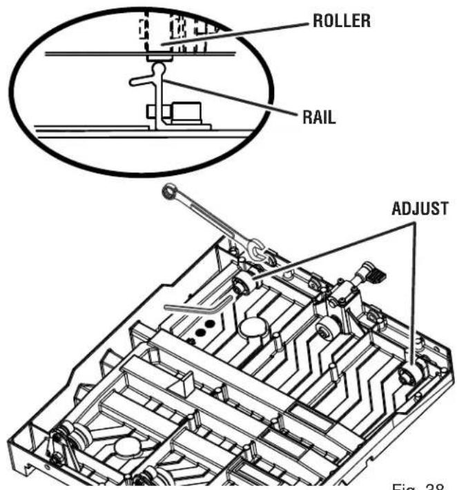
Fig. 38

Fig. 39
POSITIVE STOP ADJUSTMENTS
See Figure 40.
NOTE: These adjustments were made at the factory and normally do not require readjustment.
■ Unplug the saw.
If the wheel is not perfectly vertical (0°):
■ Loosen the bevel lock knob.
■ Raise the motor head.
■ Place a combination square beside the wheel.
■ Using a wrench, turn the 0^ hex bolt until the wheel is square to the table and the hex bolt is resting on the saw housing.
■ Tighten the bevel lock knob.
If the wheel is not an exact 45^ :
■ Set bevel to 45°.
■ Place a combination square against the wheel and set the motor head at 45^ .
■ Using a wrench, turn the 45^ hex bolt until the hex bolt is resting on the saw housing.
ALIGNING THE LASER GUIDE LINE
See Figure 41.

DANGER:
Laser radiation. Avoid direct eye contact with light source.

WARNING:
Use of controls or adjustments or performance of procedures other than those specified herein can result in hazardous radiation exposure.
■ Use the work clamp or a C-clamp to secure a piece of scrap tile.
■ Draw a line on the tile.
- Plug the saw into the power source and make a slight cut to score the tile.
■ Release the switch trigger and allow the saw blade to stop rotating before raising the wheel.
■ Roll sliding table away from cutting wheel. Lower and lock motor head.
■ Turn on the laser.
■ To adjust the laser line, open the cutting wheel guard, loosen the Phillips head screw, adjust the laser module as needed, and tighten the screw securely.
■ Once aligned, close and lock the wheel guard.
NOTE: Always make practice cuts on scrap material before cutting through your workpiece.


natural_image
Technical line drawing of a mechanical assembly with rollers and conveyor system (no text or symbols)
Fig. 41

WARNING:
When servicing, use only identical RIDGID replacement parts. Use of any other parts can create a hazard or cause product damage.

WARNING:
Always wear eye protection with side shields marked to comply with ANSI Z87.1 along with hearing and breathing protection. during product operation. If operation is dusty, also wear a dust mask.
GENERAL MAINTENANCE
Avoid using solvents when cleaning plastic parts. Most plastics are susceptible to damage from various types of commercial solvents and may be damaged by their use. Use clean cloths to remove dirt, dust, oil, grease, etc.

WARNING:
Do not at any time let brake fluids, gasoline, petroleum-based products, penetrating oils, etc., come in contact with plastic parts. Chemicals can damage, weaken or destroy plastic which can result in serious personal injury.
LUBRICATION
All of the bearings in this tool are lubricated with a sufficient amount of high grade lubricant for the life of the unit under normal operating conditions. After extended use, clean the rails so the table will roll smoothly.
BRUSH REPLACEMENT
See Figure 42.
The saw motor has externally accessible brush assemblies that should be periodically checked for wear.
Proceed as follows when replacement is required:
■ Unplug the saw.
■ Remove brush cap with a screwdriver. Brush assembly is spring loaded and will pop out when you remove brush cap.
■ Remove brush assembly.
- Check for wear. Replace both brushes when either has less than 1/4 in. length of carbon remaining. Do not replace one side without replacing the other.
■ Reassemble using new brush assemblies. Make sure curvature of brush matches curvature of motor and that brush moves freely in brush tube.
■ Make sure brush cap is oriented correctly (straight) and replace.
■ Tighten brush cap securely. Do not overtighten.

CLEANING THE RAILS
During use, the rails will become dirty preventing the table rollers from rolling smoothly. Be sure to wash off and wipe clean the rails often.
CLEANING THE SAW
■ Unplug the saw and water pump.
■ Empty the dirty water from the water tray and replace with clean water.
■ Run clean water through the saw flushing debris through the tube and around the cutting wheel.
■ Remove sliding table.
■ Once the table has been removed, rinse the rails and water tray, and water tray frame.
■ Replace the drain cap. Tighten securely.
■ Empty dirty water from the water tray and dry off the tool.
CLEANING THE SUBMERSIBLE PUMP
■ Unplug pump before handling or cleaning the pump.
■ Remove the front cover.
■ Using a small brush and/or water, clean any debris or trash that is trapped on the inside of the pump.
NOTE: To maintain efficiency and extend the life of the pump, check intake screen before use to make sure it is clean.
■ Rinse filter with clean water.
If the pump will not run, try the following solutions:
■ Ensure that the intake screen is free of obstructions.
■ Make sure that the water hose isn't clogged or knotted.
■ Be sure the unit is plugged into a functioning power outlet and the pump is plugged into the electrical plug.
- Be sure there is adequate water in the water tank and that the pump's water flow selector is set to "MAX".
NOTE: Do not handle the pump while it is connected to a power source.
RIDGID® HAND HELD AND STATIONARY POWER TOOL 3 YEAR LIMITED SERVICE WARRANTY
Proof of purchase must be presented when requesting warranty service.
Limited to RIDGID® hand held and stationary power tools purchased 2/1/04 and after. This product is manufactured by One World Technologies, Inc. The trademark is licensed from RIDGID®, Inc. All warranty communications should be directed to One World Technologies, Inc., attn: RIDGID® Hand Held and Stationary Power Tool Technical Service at (toll free) 1-866-539-1710.
90-DAY SATISFACTION GUARANTEE POLICY
During the first 90 days after the date of purchase, if you are dissatisfied with the performance of this RIDGID® Hand Held and Stationary Power Tool for any reason you may return the tool to the dealer from which it was purchased for a full refund or exchange. To receive a replacement tool you must present proof of purchase and return all original equipment packaged with the original product. The replacement tool will be covered by the limited warranty for the balance of the 3 YEAR service warranty period.
WHAT IS COVERED UNDER THE 3 YEAR LIMITED SERVICE WARRANTY
This warranty on RIDGID® Hand Held and Stationary Power Tools covers all defects in workmanship or materials and normal wear items such as brushes, chucks, motors, switches, cords, gears and even cordless batteries in this RIDGID® tool for three years following the purchase date of the tool. Warranties for other RIDGID® products may vary.
HOW TO OBTAIN SERVICE
To obtain service for this RIDGID® tool you must return it; freight prepaid, or take it in to an authorized service center for RIDGID® branded hand held and stationary power tools. You may obtain the location of the authorized service center nearest you by calling (toll free) 1-866-539-1710 or by logging on to the RIDGID® website at www.ridgid.com. When requesting warranty service, you must present the original dated sales receipt. The authorized service center will repair any faulty workmanship, and either repair or replace any part covered under the warranty, at our option, at no charge to you.
WHAT IS NOT COVERED
This warranty applies only to the original purchaser at retail and may not be transferred. This warranty only covers defects arising under normal usage and does not cover any malfunction, failure or defect resulting from misuse, abuse, neglect, alteration, modification or repair by other than an authorized service center for RIDGID® branded hand held and stationary power tools. Consumable accessories provided with the tool such as, but not limited to, blades, bits and sand paper are not covered.
RIDGID®, INC. AND ONE WORLD TECHNOLOGIES, INC. MAKE NO WARRANTIES, REPRESENTATIONS OR PROMISES AS TO THE QUALITY OR PERFORMANCE OF ITS POWER TOOLS OTHER THAN THOSE SPECIFICALLY STATED IN THIS WARRANTY.
ADDITIONAL LIMITATIONS
To the extent permitted by applicable law, all implied warranties, including warranties of MERCHANTABILITY or FITNESS FOR A PARTICULAR PURPOSE, are disclaimed. Any implied warranties, including warranties of merchantability or fitness for a particular purpose, that cannot be disclaimed under state law are limited to three years from the date of purchase. One World Technologies, Inc. and RIDGID®, Inc. are not responsible for direct, indirect, incidental or consequential damages. Some states do not allow limitations on how long an implied warranty lasts and/or do not allow the exclusion or limitation of incidental or consequential damages, so the above limitations may not apply to you. This warranty gives you specific legal rights, and you may also have other rights which vary from state to state.
One World Technologies, Inc.
P.O. Box 1427
Anderson, SC 29622

AVERTISSEMENT :
Fig. 5
natural_image
Technical line drawing of a mechanical assembly with no visible text or symbolsFig. 9
INSTALLATION DES TABLE COULISSSANTE
Voir la figure 10.
natural_image
Line drawing of a person walking with a luggage cart, no text or symbols presentFig. 18
UTILISATION

AVERTISSEMENT :
Fig. 21
POUR EFFECTUER UNE COUPE TRANSVERSALE / REFENTE
Voir la figure 22.
natural_image
Technical line drawing of a mechanical assembly with no visible text or symbolsFig. 23
POUR EFFECTUER UNE COUPE D'ONGLET
Voir la figure 24.
natural_image
Technical line drawing of a mechanical assembly with rollers and conveyor system (no text or symbols)Fig. 24
COUPE EN L

natural_image
Technical line drawing of an automotive chassis frame with conveyor and chassis components (no text or symbols)Fig. 25
POUR EFFECTUER UNE COUPE BISEAU
Voir la figure 26.
natural_image
Technical line drawing of a 3D printer or machine with no visible text or symbolsPOUR EFFECTUER LA COUPE DE PIERRE À JARDIN
natural_image
Diagram illustrating a mechanical assembly process with three stages: cutting, forming a block, and finally pressing a material (no text or symbols present)Fig. 28

Fig. 30
natural_image
Technical line drawing of a mechanical assembly with internal components and a flat panel (no text or symbols)Fig. 35
natural_image
Technical line drawing of a mechanical assembly with no visible text or symbolsFig. 40

Fig. 41

AVERTISSEMENT :
RÉPARATIONS SOUS GARANTIE
One World Technologies, Inc.
P.O. Box 1427
Anderson, SC 29622

ADVERTENCIA:
natural_image
Line drawing of a black electrical outlet plug with two leads (no text or symbols)natural_image
Line drawing of a person walking with luggage, no text or symbols presentFig. 18
FUNCIONAMIENTO

ADVERTENCIA:
Fig. 21
PARA EFECTUAR CORTES TRANSVERSALES / CORTE AL HILO
Vea la figura 22.
natural_image
Technical line drawing of a mechanical assembly with rollers and brackets (no text or symbols)Fig. 24

Fig. 25
PARA EFECTUAR CORTES EN BISEL
Vea la figura 26.
natural_image
Technical line drawing of a 3D printer or machine with a paper plane and mechanical components, showing no text or symbols.Fig. 28

Fig. 30
Cortar adoquines para esquinas:
Fig. 34
REALIZAR AJUSTES SOBRE LA MESA DESLIZABLE
natural_image
Technical line drawing of a mechanical assembly with internal components and a flat plate (no text or symbols)Fig. 35
natural_image
Technical line drawing of a mechanical assembly with rollers and conveyor system (no text or symbols)Fig. 40

Fig. 41

ADVERTENCIA:
One World Technologies, Inc.
P.O. Box 1427
Anderson, SC 29622
OPERATOR'S MANUAL
MANUEL D'UTILISATION
MANUAL DEL OPERADOR
8 in. TILE AND PAVER SAW WITH LASER
SCIE À CARREAUX ET PAVES SOUS EAU DE 203 mm (8 po) AVEC LASER
SIERRA PARA LOSAS Y PAVIMENTO DE 203 mm (8 pulg.) CON LÁSER
R4040
Customer Service Information:
For parts or service, do not return this product to the store. Contact your nearest RIDGID® authorized service center. Be sure to provide all relevant information when you call or visit. For the location of the authorized service center nearest you, please call 1-866-539-1710 or visit us online at www.RIDGID.com.
MODEL NO. ____ SERIAL NO. ____
RIDGID is a registered trademark of RIDGID, Inc., used under license.


- RIDG ^
- OPERATOR'S MANUAL
- MANUEL D'UTILISATION
- MANUAL DEL OPERADOR
- in. TILE AND PAVER SAW WITH LASER
- SCIE À CARREAUX ET PAVES SOUS EAU
- DE 203 mm (8 po) AVEC LASER
- SIERRA PARA LOSAS Y PAVIMENTO
- DE 203 mm (8 pulg.) CON LÁSER
- WARNING:
- SAVE THIS MANUAL FOR FUTURE REFERENCE
- INTRODUCTION
- READ ALL INSTRUCTIONS
- SPECIFIC SAFETY RULES
- EXTENSION CORDS
- ELECTRICAL CONNECTION
- SPEED AND WIRING
- GROUNDING INSTRUCTIONS
- POSITION OF THE TILE SAW
- See Figure 2.
- PRODUCT SPECIFICATIONS
- KNOW YOUR TILE SAW
- TOOLS NEEDED
- UNPACKING
- INSTALLING MOTOR HEAD ASSEMBLY TO FRAME
- INSTALLING WATER FILTER AND WATER PUMP
- INSTALLING WATER TRAY
- See Figure 8 - 9.
- INSTALLING THE SLIDING TABLE
- To install the sliding table:
- To lock sliding table:
- To unlock the sliding table:
- TILE CUTTING WHEEL
- INSTALLING THE CUTTING WHEEL
- INSTALLING SPLASH GUARD ASSEMBLY
- Attaching rear splash guard:
- Attaching side splash guard:
- INSTALLING WATER TRAY EXTENSDN
- See Figure 15.
- INSTALLING THE MITER GUIDE
- See Figure 16.
- To adjust angles:
- FILLING/CHANGING THE WATER RESERVOIR
- See Figure 17.
- To change reservoir water:
- TRANSPORTING THE TILE SAW
- OPERATION
- APPLICATIONS
- ON/OFF SWITCH
- LOCKING/UNLOCKING THE MOTOR HEAD FOR PLUNGE CUTS
- MAKING CUTS
- DANGER:
- USING THE LASER GUIDE
- Removing Your Mark:
- To Cut Your Mark:
- To Leave Your Mark:
- TO MAKE A CROSS CUT / RIP CUT
- TO MAKE A DIAGONAL CUT
- TO MAKE A MITER CUT
- See Figure 24.
- TO MAKE AN L-CUT
- See Figure 25.
- TO MAKE A BEVEL CUT
- MAKING GARDEN PAVER CUTS
- To cut paver shorter:
- To make paver for corners:
- TO SQUARE THE CUTTING WHEEL TO THE TABLE
- TO ADJUST SLIDING TABLE
- To adjust the center upper cam roller:
- To adjust the lower cam rollers:
- To adjust the right side cam rollers:
- DEPTH STOP ADJUSTMENTS
- POSITIVE STOP ADJUSTMENTS
- ALIGNING THE LASER GUIDE LINE
- GENERAL MAINTENANCE
- LUBRICATION
- BRUSH REPLACEMENT
- Proceed as follows when replacement is required:
- CLEANING THE RAILS
- CLEANING THE SAW
- CLEANING THE SUBMERSIBLE PUMP
- If the pump will not run, try the following solutions:
- RIDGID® HAND HELD AND STATIONARY POWER TOOL 3 YEAR LIMITED SERVICE WARRANTY
- 90-DAY SATISFACTION GUARANTEE POLICY
- WHAT IS COVERED UNDER THE 3 YEAR LIMITED SERVICE WARRANTY
- HOW TO OBTAIN SERVICE
- WHAT IS NOT COVERED
- ADDITIONAL LIMITATIONS
- AVERTISSEMENT :
- INSTALLATION DES TABLE COULISSSANTE
- UTILISATION
- POUR EFFECTUER UNE COUPE TRANSVERSALE / REFENTE
- POUR EFFECTUER UNE COUPE D'ONGLET
- POUR EFFECTUER UNE COUPE BISEAU
- POUR EFFECTUER LA COUPE DE PIERRE À JARDIN
- RÉPARATIONS SOUS GARANTIE
- ADVERTENCIA:
- FUNCIONAMIENTO
- PARA EFECTUAR CORTES TRANSVERSALES / CORTE AL HILO
- PARA EFECTUAR CORTES EN BISEL
- Cortar adoquines para esquinas:
- REALIZAR AJUSTES SOBRE LA MESA DESLIZABLE
- SCIE À CARREAUX ET PAVES SOUS EAU DE 203 mm (8 po) AVEC LASER
- SIERRA PARA LOSAS Y PAVIMENTO DE 203 mm (8 pulg.) CON LÁSER
- R4040
- Customer Service Information:
Brand : RIDGID
Model : R4040S
Category : Saw