GA5040CZ1 - Electric saw MAKITA - Free user manual and instructions
Find the device manual for free GA5040CZ1 MAKITA in PDF.
| Product type | Electric saw (angle grinder) |
| Brand | Makita |
| Model | GA5040CZ1 |
| Wheel diameter | 125 mm (5 in) |
| No-load speed | 11,000 min⁻¹ (variable 2,800 to 11,000 min⁻¹) |
| Overall length | 303 mm |
| Net weight | 2.5 kg (according to EPTA 01/2003) |
| Power supply | Single-phase, double insulation, voltage according to rating plate |
| Applications | Grinding, sanding, cutting of metal and stone (without water) |
| Safety | Protective guard, shaft lock, mechanical brake (41C models), protection against accidental restart |
| Main functions | Constant speed control, soft start, overload protection |
| Maintenance and cleaning | Clean ventilation openings regularly; do not use solvents |
| Spare parts and repairability | Use only Makita parts; repairs by authorized center |
| Optional accessories | Depressed center wheels, flap discs, flexible wheels, wire brushes, etc. |
| General information | Manual available in several languages; specifications subject to change |
Frequently Asked Questions - GA5040CZ1 MAKITA
User questions about GA5040CZ1 MAKITA
0 question about this device. Answer the ones you know or ask your own.
Ask a new question about this device
Download the instructions for your Electric saw in PDF format for free! Find your manual GA5040CZ1 - MAKITA and take your electronic device back in hand. On this page are published all the documents necessary for the use of your device. GA5040CZ1 by MAKITA.
USER MANUAL GA5040CZ1 MAKITA
GB Angle Grinder Instruction Manual
natural_image
Line drawing of a mechanical power tool with a central blade and surrounding blades (no text or symbols)

natural_image
Technical line drawing of a mechanical device with a grinding tool (no text or symbols)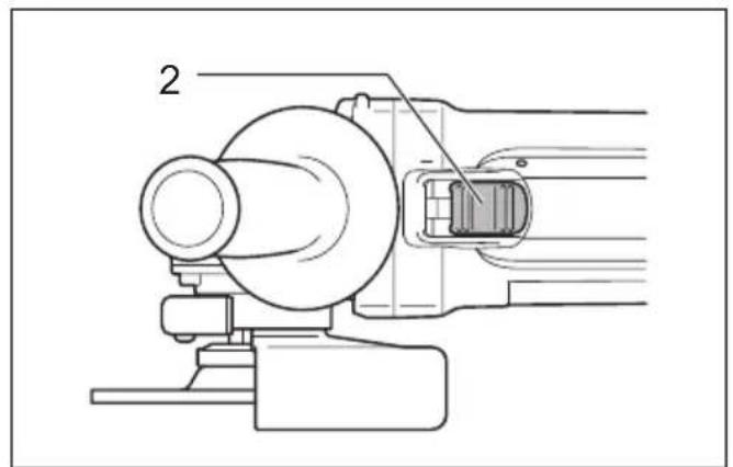
natural_image
Technical line drawing of a mechanical assembly with no visible text or symbols012725 012728
1
natural_image
Technical line drawing of a mechanical component with labeled parts (no text or symbols present)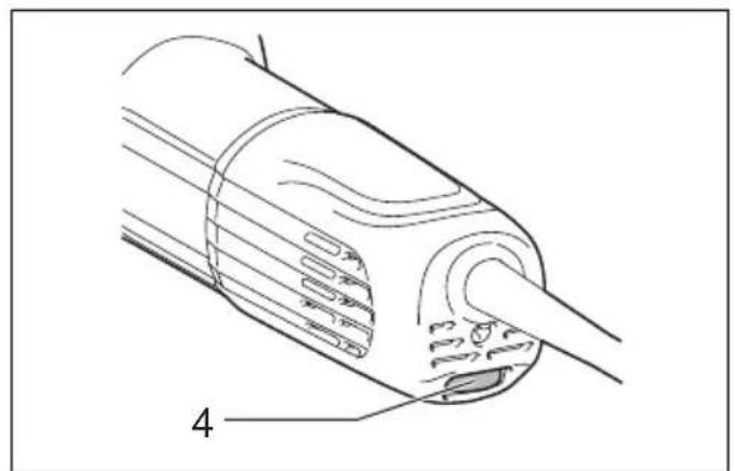
natural_image
Technical line drawing of a mechanical component with labeled parts (no text or symbols present)012729 012747 4
3

natural_image
Technical line drawing of a mechanical device with two arms and a central hub (no text or symbols)
text_image
5 6 7012724 012736
5
text_image
5 6 7 8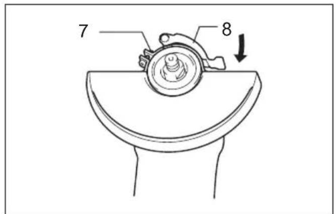
text_image
7 87
009430 009431
8
text_image
9 10 119
text_image
1 12012802 012727 10
text_image
13 14 11 1511 12
natural_image
Line drawing of hands operating a mechanical device with a circular component and a directional arrow (no text or symbols)012772
012773
text_image
16 1713 14
natural_image
Mechanical gear mechanism diagram showing rotational motion with no text or symbols010846 010863
text_image
9 18 19 1115 16
text_image
20 21 22012740 012742

text_image
23 24 25 26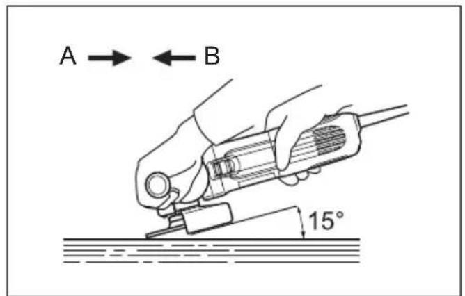
text_image
A → ← B 15°012731 012730
17 18
text_image
9 27 11 28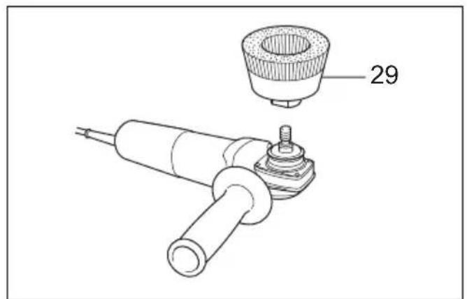
text_image
29010855 012743
19 20
text_image
30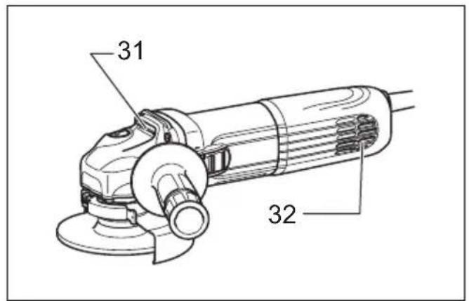
text_image
31 3221 22
012744 012732
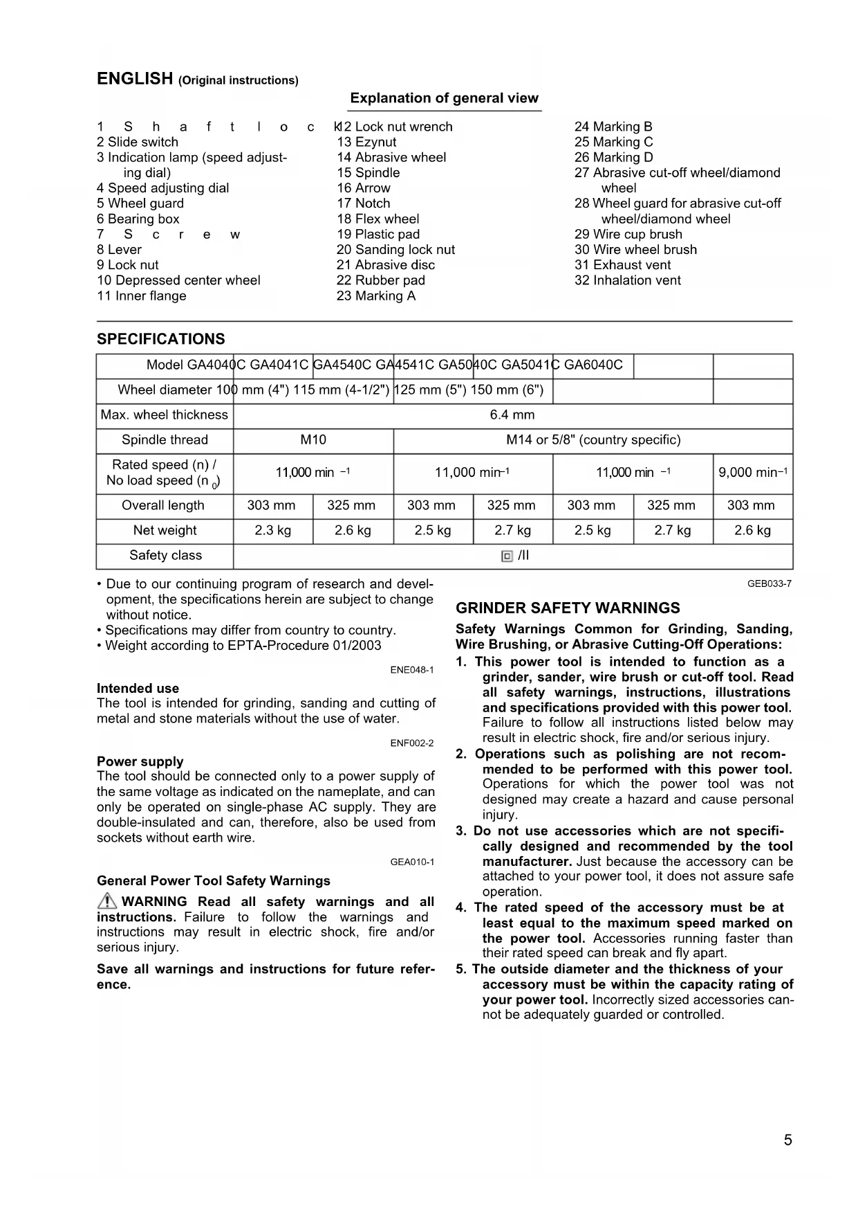
ENGLISH (Original instructions)
| Explanation of general view | ||
| 1 S h a f t l o c | K12 Lock nut wrench | 24 Marking B |
| 2 Slide switch | 13 Ezynut | 25 Marking C |
| 3 Indication lamp (speed adjusting dial) | 14 Abrasive wheel | 26 Marking D |
| 15 Spindle | 27 Abrasive cut-off wheel/diamond wheel | |
| 4 Speed adjusting dial | 16 Arrow | |
| 5 Wheel guard | 17 Notch | 28 Wheel guard for abrasive cut-off wheel/diamond wheel |
| 6 Bearing box | 18 Flex wheel | |
| 7 S c r e w | 19 Plastic pad | 29 Wire cup brush |
| 8 Lever | 20 Sanding lock nut | 30 Wire wheel brush |
| 9 Lock nut | 21 Abrasive disc | 31 Exhaust vent |
| 10 Depressed center wheel | 22 Rubber pad | 32 Inhalation vent |
| 11 Inner flange | 23 Marking A | |
SPECIFICATIONS
| Model GA4040 | C GA4041C | GA4540C GA | 4541C GA50 | 40C GA5041 | C GA6040C | ||
| Wheel diameter 100 mm (4") 115 mm (4-1/2") | 125 mm (5") 150 mm (6") | ||||||
| Max. wheel thickness | 6.4 mm | ||||||
| Spindle thread | M10 | M14 or 5/8" (country specific) | |||||
| Rated speed (n) / No load speed (n0) | 11,000 min -1 | 11,000 min-1 | 11,000 min -1 | 9,000 min-1 | |||
| Overall length | 303 mm | 325 mm | 303 mm | 325 mm | 303 mm | 325 mm | 303 mm |
| Net weight | 2.3 kg | 2.6 kg | 2.5 kg | 2.7 kg | 2.5 kg | 2.7 kg | 2.6 kg |
| Safety class | ☐ /II | ||||||
- Due to our continuing program of research and development, the specifications herein are subject to change without notice.
- Specifications may differ from country to country.
• Weight according to EPTA-Procedure 01/2003
ENE048-1
Intended use
The tool is intended for grinding, sanding and cutting of metal and stone materials without the use of water.
ENF002-2
Power supply
The tool should be connected only to a power supply of the same voltage as indicated on the nameplate, and can only be operated on single-phase AC supply. They are double-insulated and can, therefore, also be used from sockets without earth wire.
GEA010-1
General Power Tool Safety Warnings
⚠ WARNING Read all safety warnings and all instructions. Failure to follow the warnings and instructions may result in electric shock, fire and/or serious injury.
Save all warnings and instructions for future reference.
GEB033-7
GRINDER SAFETY WARNINGS
Safety Warnings Common for Grinding, Sanding, Wire Brushing, or Abrasive Cutting-Off Operations:
- This power tool is intended to function as a grinder, sander, wire brush or cut-off tool. Read all safety warnings, instructions, illustrations and specifications provided with this power tool. Failure to follow all instructions listed below may result in electric shock, fire and/or serious injury.
- Operations such as polishing are not recommended to be performed with this power tool. Operations for which the power tool was not designed may create a hazard and cause personal injury.
- Do not use accessories which are not specifically designed and recommended by the tool manufacturer. Just because the accessory can be attached to your power tool, it does not assure safe operation.
- The rated speed of the accessory must be at least equal to the maximum speed marked on the power tool. Accessories running faster than their rated speed can break and fly apart.
-
The outside diameter and the thickness of your accessory must be within the capacity rating of your power tool. Incorrectly sized accessories cannot be adequately guarded or controlled.
-
Threaded mounting of accessories must match the grinder spindle thread. For accessories mounted by flanges, the arbour hole of the accessory must fit the locating diameter of the flange. Accessories that do not match the mounting hardware of the power tool will run out of balance, vibrate excessively and may cause loss of control.
- Do not use a damaged accessory. Before each use inspect the accessory such as abrasive wheels for chips and cracks, backing pad for cracks, tear or excess wear, wire brush for loose or cracked wires. If power tool or accessory is dropped, inspect for damage or install an undamaged accessory. After inspecting and installing an accessory, position yourself and bystanders away from the plane of the rotating accessory and run the power tool at maximum no-load speed for one minute. Damaged accessories will normally break apart during this test time.
- Wear personal protective equipment. Depending on application, use face shield, safety goggles or safety glasses. As appropriate, wear dust mask, hearing protectors, gloves and workshop apron capable of stopping small abrasive or workpiece fragments. The eye protection must be capable of stopping flying debris generated by various operations. The dust mask or respirator must be capable of filtrating particles generated by your operation. Prolonged exposure to high intensity noise may cause hearing loss.
- Keep bystanders a safe distance away from work area. Anyone entering the work area must wear personal protective equipment. Fragments of workpiece or of a broken accessory may fly away and cause injury beyond immediate area of operation.
- Hold the power tool by insulated gripping surfaces only, when performing an operation where the cutting accessory may contact hidden wiring or its own cord. Cutting accessory contacting a "live" wire may make exposed metal parts of the power tool "live" and could give the operator an electric shock.
- Position the cord clear of the spinning accessory. If you lose control, the cord may be cut or snagged and your hand or arm may be pulled into the spinning accessory.
- Never lay the power tool down until the accessory has come to a complete stop. The spinning accessory may grab the surface and pull the power tool out of your control.
- Do not run the power tool while carrying it at your side. Accidental contact with the spinning accessory could snag your clothing, pulling the accessory into your body.
- Regularly clean the power tool's air vents. The motor's fan will draw the dust inside the housing and excessive accumulation of powdered metal may cause electrical hazards.
- Do not operate the power tool near flammable materials. Sparks could ignite these materials.
- Do not use accessories that require liquid coolants. Using water or other liquid coolants may result in electrocution or shock.
Kickback and Related Warnings
Kickback is a sudden reaction to a pinched or snagged rotating wheel, backing pad, brush or any other accessory. Pinching or snagging causes rapid stalling of the rotating accessory which in turn causes the uncontrolled power tool to be forced in the direction opposite of the accessory's rotation at the point of the binding.
For example, if an abrasive wheel is snagged or pinched by the workpiece, the edge of the wheel that is entering into the pinch point can dig into the surface of the material causing the wheel to climb out or kick out. The wheel may either jump toward or away from the operator, depending on direction of the wheel's movement at the point of pinching. Abrasive wheels may also break under these conditions.
Kickback is the result of power tool misuse and/or incorrect operating procedures or conditions and can be avoided by taking proper precautions as given below.
a) Maintain a firm grip on the power tool and position your body and arm to allow you to resist kickback forces. Always use auxiliary handle, if provided, for maximum control over kickback or torque reaction during start-up. The operator can control torque reactions or kickback forces, if proper precautions are taken.
b) Never place your hand near the rotating accessory. Accessory may kickback over your hand.
c) Do not position your body in the area where power tool will move if kickback occurs. Kickback will propel the tool in direction opposite to the wheel's movement at the point of snagging.
d) Use special care when working corners, sharp edges etc. Avoid bouncing and snagging the accessory. Corners, sharp edges or bouncing have a tendency to snag the rotating accessory and cause loss of control or kickback.
e) Do not attach a saw chain woodcarving blade or toothed saw blade. Such blades create frequent kickback and loss of control.
Safety Warnings Specific for Grinding and Abrasive Cutting-Off Operations:
a) Use only wheel types that are recommended for your power tool and the specific guard designed for the selected wheel. Wheels for which the power tool was not designed cannot be adequately guarded and are unsafe.
b) The grinding surface of centre depressed wheels must be mounted below the plane of the guard lip. An improperly mounted wheel that projects through the plane of the guard lip cannot be adequately protected.
c) The guard must be securely attached to the power tool and positioned for maximum safety, so the least amount of wheel is exposed towards the operator. The guard helps to protect the operator from broken wheel fragments, accidental contact with wheel and sparks that could ignite clothing.
d) Wheels must be used only for recommended applications. For example: do not grind with the side of cut-off wheel. Abrasive cut-off wheels are intended for peripheral grinding, side forces applied to these wheels may cause them to shatter.
e) Always use undamaged wheel flanges that are of correct size and shape for your selected wheel. Proper wheel flanges support the wheel thus reducing the possibility of wheel breakage. Flanges for cut-off wheels may be different from grinding wheel flanges.
f) Do not use worn down wheels from larger power tools. Wheel intended for larger power tool is not suitable for the higher speed of a smaller tool and may burst.
Additional Safety Warnings Specific for Abrasive Cutting-Off Operations:
a) Do not “jam” the cut-off wheel or apply excessive pressure. Do not attempt to make an excessive depth of cut. Overstressing the wheel increases the loading and susceptibility to twisting or binding of the wheel in the cut and the possibility of kickback or wheel breakage.
b) Do not position your body in line with and behind the rotating wheel. When the wheel, at the point of operation, is moving away from your body, the possible kickback may propel the spinning wheel and the power tool directly at you.
c) When wheel is binding or when interrupting a cut for any reason, switch off the power tool and hold the power tool motionless until the wheel comes to a complete stop. Never attempt to remove the cut-off wheel from the cut while the wheel is in motion otherwise kickback may occur. Investigate and take corrective action to eliminate the cause of wheel binding
d) Do not restart the cutting operation in the workpiece. Let the wheel reach full speed and carefully re-enter the cut. The wheel may bind, walk up or kickback if the power tool is restarted in the workpiece.
e) Support panels or any oversized workpiece to minimize the risk of wheel pinching and kickback. Large workpieces tend to sag under their own weight. Supports must be placed under the workpiece near the line of cut and near the edge of the workpiece on both sides of the wheel.
f) Use extra caution when making a "pocket cut" into existing walls or other blind areas. The protruding wheel may cut gas or water pipes, electrical wiring or objects that can cause kickback.
Safety Warnings Specific for Sanding Operations:
a) Do not use excessively oversized sanding disc paper. Follow manufacturers recommendations, when selecting sanding paper. Larger sanding paper extending beyond the sanding pad presents a laceration hazard and may cause snagging, tearing of the disc or kickback.
Safety Warnings Specific for Wire Brushing Operations:
a) Be aware that wire bristles are thrown by the brush even during ordinary operation. Do not overstress the wires by applying excessive load to the brush. The wire bristles can easily penetrate light clothing and/or skin.
b) If the use of a guard is recommended for wire brushing, do not allow interference of the wire wheel or brush with the guard. Wire wheel or brush may expand in diameter due to work load and centrifugal forces.
Additional safety warnings:
- When using depressed centre grinding wheels, be sure to use only fiberglass-reinforced wheels.
- NEVER USE Stone Cup type wheels with this grinder. This grinder is not designed for these types of wheels and the use of such a product may result in serious personal injury.
- Be careful not to damage the spindle, the flange (especially the installing surface) or the lock nut. Damage to these parts could result in wheel breakage.
- Make sure the wheel is not contacting the workpiece before the switch is turned on.
- Before using the tool on an actual workpiece, let it run for a while. Watch for vibration or wobbling that could indicate poor installation or a poorly balanced wheel.
- Use the specified surface of the wheel to perform the grinding.
- Do not leave the tool running. Operate the tool only when hand-held.
- Do not touch the workpiece immediately after operation; it may be extremely hot and could burn your skin.
- Observe the instructions of the manufacturer for correct mounting and use of wheels. Handle and store wheels with care.
- Do not use separate reducing bushings or adaptors to adapt large hole abrasive wheels.
- Use only flanges specified for this tool.
- For tools intended to be fitted with threaded hole wheel, ensure that the thread in the wheel is long enough to accept the spindle length.
- Check that the workpiece is properly supported.
- Pay attention that the wheel continues to rotate after the tool is switched off.
- If working place is extremely hot and humid, or badly polluted by conductive dust, use a short-circuit breaker (30 mA) to assure operator safety.
- Do not use the tool on any materials containing asbestos.
- When use cut-off wheel, always work with the dust collecting wheel guard required by domestic regulation.
- Cutting discs must not be subjected to any lateral pressure.
SAVE THESE INSTRUCTIONS.
WARNING:
DO NOT let comfort or familiarity with product (gained from repeated use) replace strict adherence to safety rules for the subject product. MISUSE or failure to follow the safety rules stated in this instruction manual may cause serious personal injury.
FUNCTIONAL DESCRIPTION
CAUTION:
- Always be sure that the tool is switched off and unplugged before adjusting or checking function on the tool.
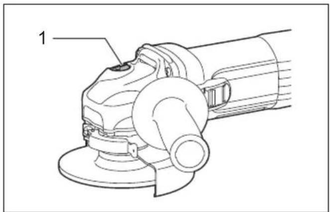
Shaft lock (Fig. 1)
CAUTION:
- Never actuate the shaft lock when the spindle is moving. The tool may be damaged.
Press the shaft lock to prevent spindle rotation when installing or removing accessories.
Switch action (Fig. 2)
CAUTION:
- Before plugging in the tool, always check to see that the slide switch actuates properly and returns to the "OFF" position when the rear of the slide switch is depressed.
- Switch can be locked in "ON" position for ease of operator comfort during extended use. Apply caution when locking tool in "ON" position and maintain firm grasp on tool.
To start the tool, slide the slide switch toward the "I (ON)" position by pushing the rear of the slide switch. For continuous operation, press the front of the slide switch to lock it.
To stop the tool, press the rear of the slide switch, then slide it toward the "O (OFF)" position.
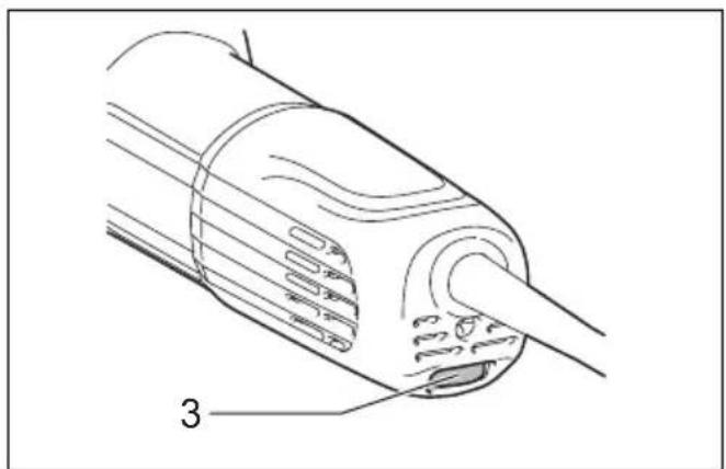
Indication lamp (Fig. 3)
The indication lamp lights up green when the tool is plugged. If the indication lamp does not light up, the mains cord or the controller may be defective. The indication lamp is lit but the tool does not start even if the tool is switched on, the carbon brushes may be worn out, or the controller, the motor or the ON/OFF switch may be defective.
Unintentional restart proof
The tool does not start with the switch being lock-on even when the tool is plugged.
At this time, the indication lamp flickers red and shows the unintentional restart proof device is on function.
To cancel the unintentional restart proof, return the slide switch to "O (OFF)" position.
Speed adjusting dial (Fig. 4)
The rotating speed can be changed by turning the speed adjusting dial to a given number setting from 1 to 5.
Higher speed is obtained when the dial is turned in the direction of number 5. And lower speed is obtained when it is turned in the direction of number 1.
Refer to the below table for the relationship between the number settings on the dial and the approximate rotating speed.
For model GA4040C, GA4540C, GA5040C, GA4041C, GA4541C, GA5041C
| Number min | -1 (R.P.M.) |
| 1 | 2 |
| 2 | 4 |
| 3 | 6 |
| 4 | 8 |
| 5 | 1 |
012752
For model GA6040C
| Number min | -1 (R.P.M.) |
| 1 4,000 | |
| 2 5,000 | |
| 3 6,000 | |
| 4 7,000 | |
| 5 9,000 |
012756
CAUTION:
- If the tool is operated continuously at low speeds for a long time, the motor will get overloaded and heated up.
- The speed adjusting dial can be turned only as far as 5 and back to 1. Do not force it past 5 or 1, or the speed adjusting function may no longer work.
Electronic function
The tools equipped with electronic function are easy to operate because of the following features.
Constant speed control
Constant speed control provides fine finish by keeping the rotating speed constant under the loaded condition.
Soft start feature
Soft start feature suppresses starting shock.
Overload protector
When the load on the tool exceeds admissible levels, power to the motor is reduced to protect the motor from overheating. When the load returns to admissible levels, the tool will operate as normal.
Mechanical brake
For model GA4041C, GA4541C, GA5041C
Mechanical brake is activated after the tool is switched off.
The brake does not work when the power supply is shut down with the switch still on.
ASSEMBLY
CAUTION:
• Always be sure that the tool is switched off and unplugged before carrying out any work on the tool.
Installing side grip (handle) (Fig. 5)
CAUTION:
- Always be sure that the side grip is installed securely before operation.
Screw the side grip securely on the position of the tool as shown in the figure.
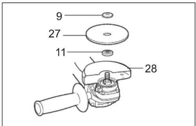
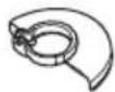
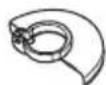
Installing or removing wheel guard (For depressed center wheel, flap disc, flex wheel, wire wheel brush / abrasive cut-off wheel, diamond wheel) 0 0
WARNING:
- When using a depressed center wheel, flap disc, flex wheel or wire wheel brush, the wheel guard must be fitted on the tool so that the closed side of the guard always points toward the operator.
- When using an abrasive cut-off / diamond wheel, be sure to use only the special wheel guard designed for use with cut-off wheels. (In some European countries, when using a diamond wheel, the ordinary guard can be used. Follow the regulations in your country.)
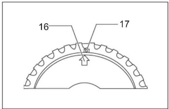
For tool with locking screw type wheel guard (Fig. 6) Mount the wheel guard with the protrusions on the wheel guard band aligned with the notches on the bearing box. Then rotate the wheel guard around 180° counterclockwise. Be sure to tighten the screw securely.
To remove wheel guard, follow the installation procedure in reverse.
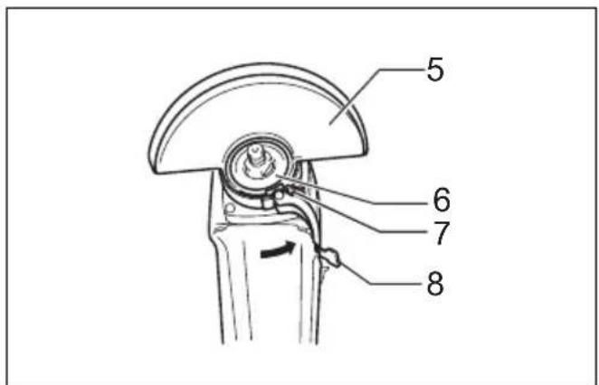
For tool with clamp lever type wheel guard (Fig. 7 & 8) Pull the lever in the direction of the arrow after loosening the screw. Mount the wheel guard with the protrusions on the wheel guard band aligned with the notches on the bearing box. Then rotate the wheel guard around 180°.
Tighten the wheel guard with fastening the screw after pulling lever in the direction of the arrow. The setting angle of the wheel guard can be adjusted with the lever. To remove wheel guard, follow the installation procedure in reverse.
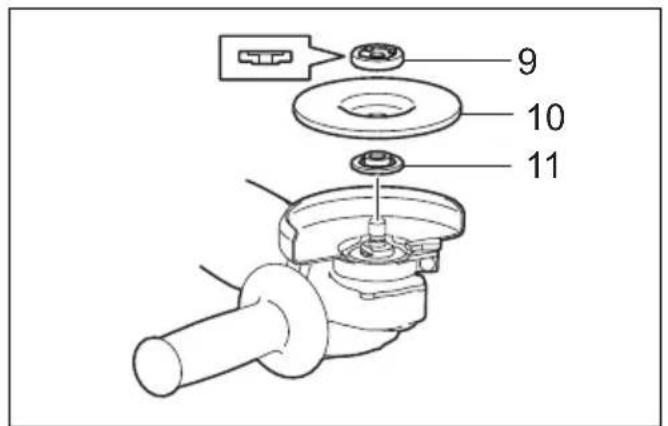
Installing or removing depressed center wheel or flap disc (optional accessory) (Fig. 9 & 10)
WARNING:
- When using a depressed center wheel or flap disc, the wheel guard must be fitted on the tool so that the closed side of the guard always points toward the operator.
Mount the inner flange onto the spindle. Fit the wheel/disc on the inner flange and screw the lock nut onto the spindle.
To tighten the lock nut, press the shaft lock firmly so that the spindle cannot revolve, then use the lock nut wrench and securely tighten clockwise.
To remove the wheel, follow the installation procedure in reverse.
Super flange (Optional accessory)
Models with the letter F are standard-equipped with Super flange. Only 1/3 of efforts needed to undo lock nut, compared with conventional type.
CAUTION:
- Do not use super flange for models equipped with the mechanical brake. Otherwise it may loosen when the brake is activated.
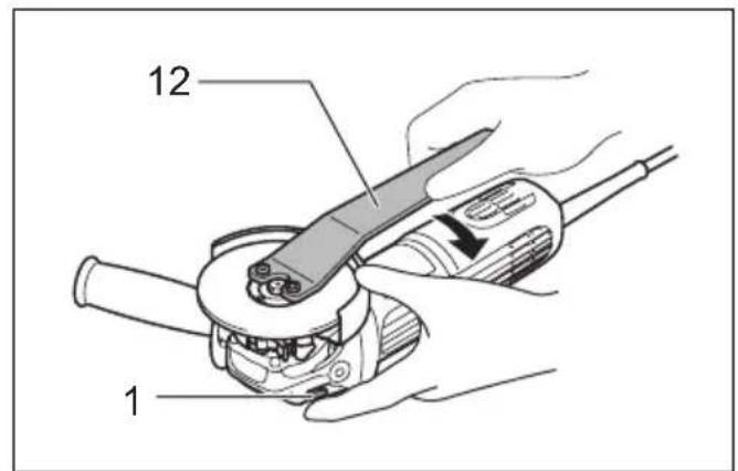
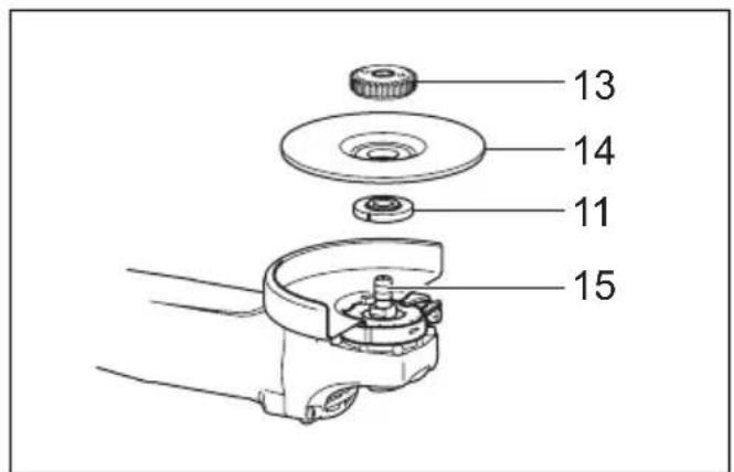
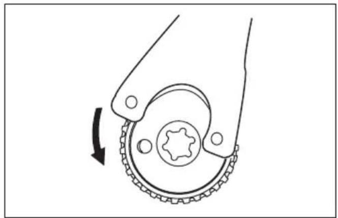
Installing or removing Ezynut (optional accessory) (Fig. 11, 12, 13 & 14)
CAUTION:
- Do not use Ezynut with Super Flange or angle grinder with "F" on the end of the model No. Those flanges are so thick that the entire thread cannot be retained by the spindle.
Mount inner flange, abrasive wheel and Ezynut onto the spindle so that Makita Logo on Ezynut faces outside.
Press shaft lock firmly and tighten Ezynut by turning the abrasive wheel clockwise as far as it turns.
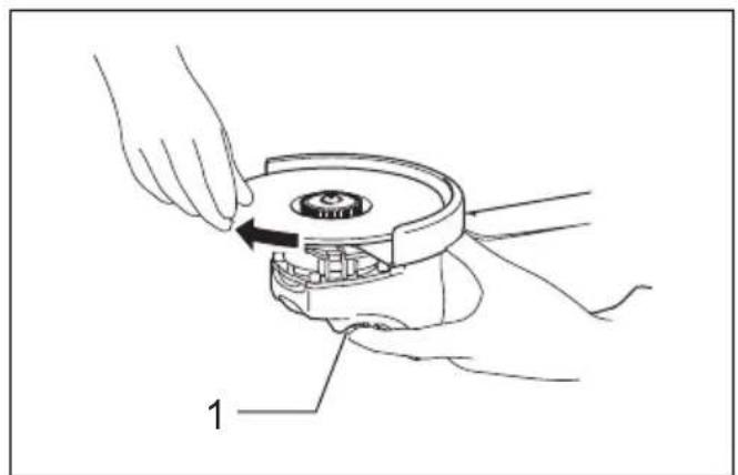
Turn the outside ring of Ezynut counterclockwise to loosen.
NOTE:
- Ezynut can be loosened by hand as long as the arrow points the notch. Otherwise a lock nut wrench is required to loosen it. Insert one pin of the wrench into a hole and turn Ezynut counterclockwise.
Installing or removing flex wheel (optional accessory) (Fig. 15)
WARNING:
- Always use supplied guard when flex wheel is on tool. Wheel can shatter during use and guard helps to reduce chances of personal injury.
Follow instructions for depressed center wheel but also use plastic pad over wheel. See order of assembly on accessories page in this manual.
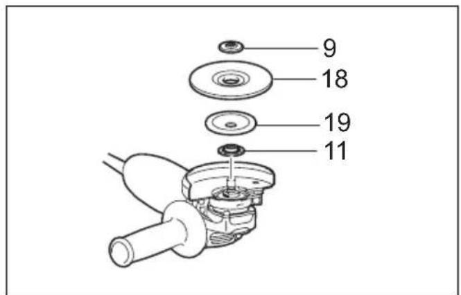
Installing or removing abrasive disc (optional accessory) (Fig. 16)
NOTE:
- Use sander accessories specified in this manual. These must be purchased separately.
Mount the rubber pad onto the spindle. Fit the disc on the rubber pad and screw the sanding lock nut onto the spindle. To tighten the sanding lock nut, press the shaft lock firmly so that the spindle cannot revolve, then use the lock nut wrench and securely tighten clockwise.
To remove the disc, follow the installation procedure in reverse.
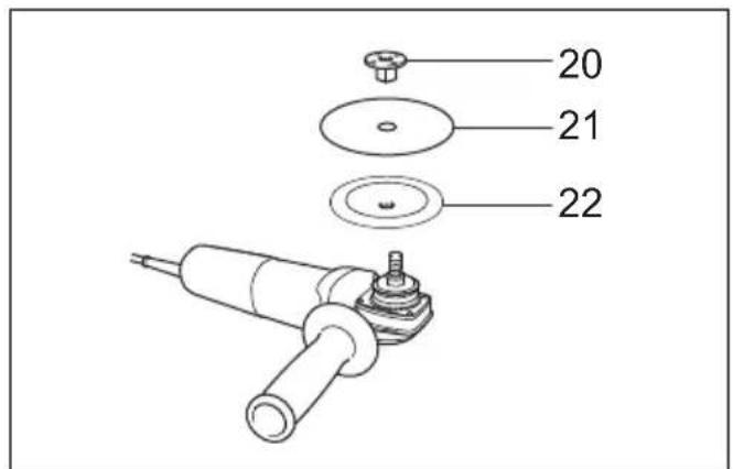
Installing or removing dust cover attachment (Optional accessory) (Fig. 17)
WARNING:
- Always be sure that the tool is switched off and unplugged before installing or removing the dust cover attachment. Failure to do so causes damage to the tool or a personal injury.
There are four pieces of dust cover attachment and each is used in one of different positions.
Set the dust cover attachment so that the marking (A, B, C or D) places as shown. Snap its pins in the vents. Dust cover attachment can be removed by hand.
NOTE:
- Clean out the dust cover attachment when it is clogged with dust or foreign matters. Continuing operation with a clogged dust cover attachment will damage the tool.
OPERATION
WARNING:
- It should never be necessary to force the tool. The weight of the tool applies adequate pressure. Forcing and excessive pressure could cause dangerous wheel breakage.
- ALWAYS replace wheel if tool is dropped while grinding.
- NEVER bang or hit grinding disc or wheel onto work.
- Avoid bouncing and snagging the wheel, especially when working corners, sharp edges etc. This can cause loss of control and kickback.
- NEVER use tool with wood cutting blades and other saw blades. Such blades when used on a grinder frequently kick and cause loss of control leading to personal injury.
CAUTION:
- Never switch on the tool when it is in contact with the workpiece, it may cause an injury to operator.
• Always wear safety goggles or a face shield during operation. - After operation, always switch off the tool and wait until the wheel has come to a complete stop before putting the tool down.
Grinding and sanding operation (Fig. 18)
ALWAYS hold the tool firmly with one hand on housing and the other on the side handle. Turn the tool on and then apply the wheel or disc to the workpiece. In general, keep the edge of the wheel or disc at an angle of about 15^ to the workpiece surface.
During the break-in period with a new wheel, do not work the grinder in the B direction or it will cut into the workpiece. Once the edge of the wheel has been rounded off by use, the wheel may be worked in both A and B direction.
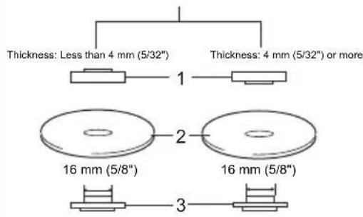
Operation with abrasive cut-off / diamond wheel (optional accessory) (Fig. 19)
The direction for mounting the lock nut and the inner flange varies by wheel thickness.
Refer to the table below.
100 mm (4") model
Abrasive cut-off wheel Diamond wheel
text_image
Thickness: Less than 4 mm (5/32") Thickness: 4 mm (5/32") or more 1 2 3 16 mm (5/8") 16 mm (5/8")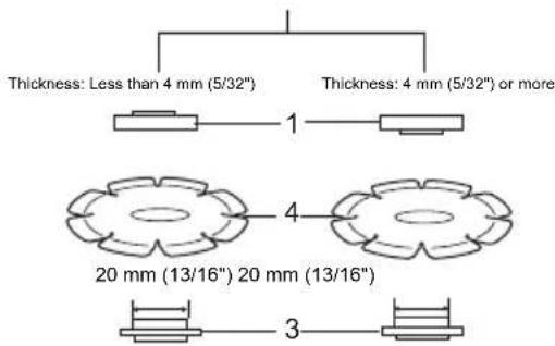
text_image
Thickness: Less than 4 mm (5/32") Thickness: 4 mm (5/32") or more 1 20 mm (13/16") 20 mm (13/16") 3- Lock nut 2. Abrasive cut-off wheel 3. Inner flange 4. Diamond wheel
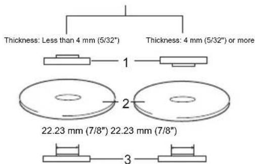
115 mm (4-1/2") / 125 mm (5") / 150 mm (6") model
Abrasive cut-off wheel Diamond wheel
text_image
Thickness: Less than 4 mm (5/32") Thickness: 4 mm (5/32") or more 1 2 22.23 mm (7/8") 22.23 mm (7/8") 3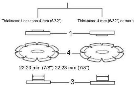
text_image
Thickness: Less than 4 mm (5/32") Thickness: 4 mm (5/32") or more 1 4 22.23 mm (7/8") 22.23 mm (7/8") 3- Lock nut 2. Abrasive cut-off wheel 3. Inner flange 4. Diamond wheel
012746
WARNING:
- When using an abrasive cut-off / diamond wheel, be sure to use only the special wheel guard designed for use with cut-off wheels. (In some European countries, when using a diamond wheel, the ordinary guard can be used. Follow the regulations in your country.)
-
NEVER use cut-off wheel for side grinding.
-
Do not "jam" the wheel or apply excessive pressure. Do not attempt to make an excessive depth of cut. Overstressing the wheel increases the loading and susceptibility to twisting or binding of the wheel in the cut and the possibility of kickback, wheel breakage and overheating of the motor may occur.
-
Do not start the cutting operation in the workpiece. Let the wheel reach full speed and carefully enter into the cut moving the tool forward over the workpiece surface. The wheel may bind, walk up or kickback if the power tool is started in the workpiece.
-
During cutting operations, never change the angle of the wheel. Placing side pressure on the cut-off wheel (as in grinding) will cause the wheel to crack and break, causing serious personal injury.
- A diamond wheel shall be operated perpendicular to the material being cut.
Operation with wire cup brush (optional accessory) (Fig. 20)
CAUTION:
- Check operation of brush by running tool with no load, insuring that no one is in front of or in line with brush.
- Do not use brush that is damaged, or which is out of balance. Use of damaged brush could increase potential for injury from contact with broken brush wires.
Unplug tool and place it upside down allowing easy access to spindle. Remove any accessories on spindle. Thread wire cup brush onto spindle and tighten with supplied wrench. When using brush, avoid applying too much pressure which causes over bending of wires, leading to premature breakage.
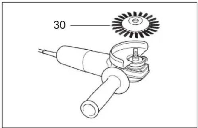
Operation with wire wheel brush (optional accessory) (Fig. 21)
CAUTION:
- Check operation of wire wheel brush by running tool with no load, insuring that no one is in front of or in line with the wire wheel brush.
- Do not use wire wheel brush that is damaged, or which is out of balance. Use of damaged wire wheel brush could increase potential for injury from contact with broken wires.
- ALWAYS use guard with wire wheel brushes, assuring diameter of wheel fits inside guard. Wheel can shatter during use and guard helps to reduce chances of personal injury.
Unplug tool and place it upside down allowing easy access to spindle. Remove any accessories on spindle. Thread wire wheel brush onto spindle and tighten with the wrenches.
When using wire wheel brush, avoid applying too much pressure which causes over bending of wires, leading to premature breakage.
MAINTENANCE
CAUTION:
- Always be sure that the tool is switched off and unplugged before attempting to perform inspection or maintenance.
- Never use gasoline, benzine, thinner, alcohol or the like. Discoloration, deformation or cracks may result.
The tool and its air vents have to be kept clean. Regularly clean the tool's air vents or whenever the vents start to become obstructed. (Fig. 22)
To maintain product SAFETY and RELIABILITY, repairs, carbon brush inspection and replacement, any other maintenance or adjustment should be performed by Makita Authorized Service Centers, always using Makita replacement parts.
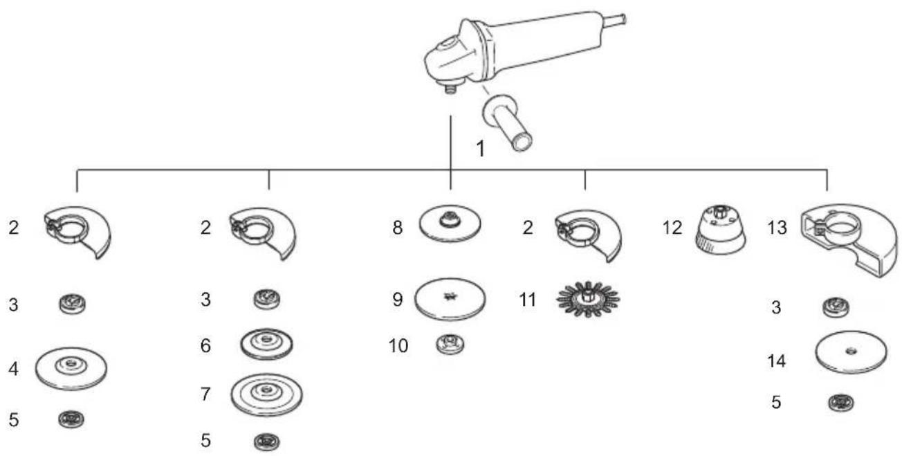
OPTIONAL ACCESSORIES
CAUTION:
• These accessories or attachments are recommended for use with your Makita tool specified in this manual. The use of any other accessories or attachments might present a risk of injury to persons. Only use accessory or attachment for its stated purpose.
If you need any assistance for more details regarding these accessories, ask your local Makita Service Center.
- Dust cover attachment
text_image
1 2 2 8 2 12 13 3 3 9 11 3 4 6 7 10 5 5 14 5| 100 mm (4") model 115 | mm (4-1/2") model 125 mm | (5") model 150 mm (6") model | ||
| 1 | G | r | ||
| 2 Wheel Guard (for grinding wheel) | ||||
| 3 Inner flange | Inner flangeSuper flange *1 | Inner flangeSuper flange *1 | Inner flangeSuper flange *1 | |
| 4 Depressed center wheel/Flap disc | ||||
| 5 Lock nut | Lock nutEzy nut *2 | Lock nutEzy nut *2 | Lock nutEzy nut *2 | |
| 6 Plastic pad Plastic pad Plastic | pad - | |||
| 7 Flex wheel Flex wheel Flex wheel | - | |||
| 8 | Rubber pad 76 | Rubber pad 100 Rubber pad 115 Rubber pad 125 | ||
| 9 | Abrasive disc | |||
| 10 | Sanding lock nut | |||
| 11 | Wire wheel brush | |||
| 12 | Wire cup brush | |||
| 13 | Wheel Guard (for cut-off wheel) *3 | |||
| 14 | Abrasive cut-off wheel/Diamond wheel | |||
| - | Lock nut wrench | |||


Note:
*1 Do not use Super flange with a grinder equipped with a brake function.
*2 Do not use Super flange and Ezynut together.
*3 In some European countries, when using a diamond wheel, the ordinary guard can be used instead of the special guard covering the both side of the wheel. Follow the regulations in your country.
013977
NOTE:
- Some items in the list may be included in the tool package as standard accessories. They may differ from country to country.
Noise
The typical A-weighted noise level determined according to EN60745:
Model GA4040C, GA4540C, GA5040C
Sound pressure level (L _nA ): 86 dB (A)
Sound power level (LWA): 97 dB (A)
Uncertainty (K): 3 dB (A)
Model GA6040C
Sound pressure level (L _pA ): 87 dB (A)
Sound power level (LWA): 98 dB (A)
Uncertainty (K): 3 dB (A)
Model GA4541C
Sound pressure level (L _pA ): 83 dB (A)
Sound power level (LWA): 94 dB (A)
Uncertainty (K): 3 dB (Å)
Model GA5041C
Sound pressure level ( L_pA ): 84 dB (A)
Sound power level (L _WA ): 95 dB (A)
Uncertainty (K): 3 dB (Å)
Wear ear protection
ENG900-1
Vibration
The vibration total value (tri-axial vector sum) determined according to EN60745:
Model GA4040C
Work mode: surface grinding with normal side grip
Vibration emission (a_h,AG) : 5.0~m / s^2
Uncertainty (K): 1.5 m/s ^2
Work mode: surface grinding with anti vibration side grip
Vibration emission (a_h AG) : 5.0~m / s^2
Uncertainty (K): 1.5 m/s ^2
Work mode: disc sanding with normal side grip
Vibration emission (a_h,DS) : 3.0~m / s^2
Uncertainty (K): 1.5 m/s ^2
Work mode: disc sanding with anti vibration side grip
Vibration emission (a_h,DS) : 2.5 m/s or less
Uncertainty (K): 1.5 m/s ^2
Model GA4540C
Work mode: surface grinding with normal side grip
Vibration emission (a_h,AG) : 6.0~m / s^2
Uncertainty (K): 1.5 m/s ^2
Work mode: surface grinding with anti vibration side grip
Vibration emission (a _h, AG ): 5.5 m/s ^2
Uncertainty (K): 1.5 m/s²
Work mode: disc sanding with normal side grip
Vibration emission (a_h,DS) : 2.5m / s^2
Uncertainty (K): 1.5 m/s ^2
Work mode: disc sanding with anti vibration side grip
Vibration emission (a_h,DS) : 2.5m / s^2
Uncertainty (K): 1.5 m/s²
Model GA5040C
Work mode: surface grinding with normal side grip
Vibration emission (a _h_AG ): 6.5 m/s ^2
Uncertainty (K): 1.5 m/s²
Work mode: surface grinding with anti vibration side grip
Vibration emission (a _h, AG ): 5.5 m/s ^2
Uncertainty (K): 1.5 m/s²
Work mode: disc sanding with normal side grip
Vibration emission (a _h_DS ): 2.5 m/s ^2
Uncertainty (K): 1.5 m/s²
Work mode: disc sanding with anti vibration side grip
Vibration emission (a _h,DS ): 2.5 m/s ^2
Uncertainty (K): 1.5 m/s²
Model GA6040C
Work mode: surface grinding with normal side grip
Vibration emission (a _h_AG ): 6.5 m/s ^2
Uncertainty (K): 1.5 m/s²
Work mode: surface grinding with anti vibration side grip
Vibration emission (a_h,AG) : 6.0~m / s^2
Uncertainty (K): 1.5 m/s²
Work mode: disc sanding with normal side grip
Vibration emission ( a_h,DS ): 2.5 m/s ^2
Uncertainty (K): 1.5 m/s ^2
Work mode: disc sanding with anti vibration side grip
Vibration emission (a _h,DS ): 2.5 m/s ^2 or less
Uncertainty (K): 1.5 m/s²
Model GA4541C
Work mode: surface grinding with normal side grip
Vibration emission (a _h AG ): 6.5 m/s ^2
Uncertainty (K): 1.5 m/s²
Work mode: surface grinding with anti vibration side grip
Vibration emission (a _h AG ): 5.5 m/s ^2
Uncertainty (K): 1.5 m/s²
Work mode: disc sanding with normal side grip
Vibration emission (a _b, DS ): 2.5 m/s ^2 or less
Uncertainty (K): 1.5 m/s²
Work mode: disc sanding with anti vibration side grip
Vibration emission (a _h_DS ): 2.5 m/s ^2 or less
Uncertainty (K): 1.5 m/s²
Model GA5041C
Work mode: surface grinding with normal side grip
Vibration emission (a _h, AG ): 7.0 m/s ^2
Uncertainty (K): 1.5 m/s²
Work mode: surface grinding with anti vibration side grip
Vibration emission (a_h,AG) : 6.0~m / s^2
Uncertainty (K): 1.5 m/s²
Work mode: disc sanding with normal side grip
Vibration emission (a _h,DS ): 2.5 m/s ^2 or less
Uncertainty (K): 1.5 m/s²
Work mode: disc sanding with anti vibration side grip
Vibration emission (a _h,DS ): 2.5 m/s ^2 or less
Uncertainty (K): 1.5 m/s²
ENG902-1
- The declared vibration emission value has been measured in accordance with the standard test method and may be used for comparing one tool with another.
- The declared vibration emission value may also be used in a preliminary assessment of exposure.
- The declared vibration emission value is used for main applications of the power tool. However if the power tool is used for other applications, the vibration emission value may be different.

WARNING:
- The vibration emission during actual use of the power tool can differ from the declared emission value depending on the ways in which the tool is used.
- Be sure to identify safety measures to protect the operator that are based on an estimation of exposure in the actual conditions of use (taking account of all parts of the operating cycle such as the times when the tool is switched off and when it is running idle in addition to the trigger time).
ENH101-16
For European countries only
EC Declaration of Conformity
We Makita Corporation as the responsible manufacturer declare that the following Makita machine(s):
Designation of Machine:
Angle Grinder
Model No./ Type: GA4040C, GA4540C, GA5040C,
GA6040C, GA4541C, GA5041C
are of series production and
Conforms to the following European Directives:
2006/42/EC
And are manufactured in accordance with the following standards or standardised documents:
EN60745
The technical documentation is kept by:
Makita International Europe Ltd.
Technical Department,
Michigan Drive, Tongwell,
Milton Keynes, Bucks MK15 8JD, England
30.8.2011

Tomoyasu Kato
Director
Makita Corporation
3-11-8, Sumiyoshi-cho,
Anjo, Aichi, 446-8502, JAPAN
Descriptif
GA6040C, GA4541C, GA5041C
Michigan Drive, Tongwell,
Milton Keynes, Bucks MK15 8JD, Angleterre
30.8.2011

Tomoyasu Kato
Directeur
Makita Corporation
3-11-8, Sumiyoshi-cho,
Anjo, Aichi, 446-8502, JAPAN
Übersicht
Vibrationsemission ( a_h, AG ): 5,0 m/s ^2
Vibrationsemission (a _h,DS ): 3,0 m/s ^2
Vibrationsemission (a _h_AG ): 6,0 m/s ^2
Vibrationsemission (a _h,DS ): 2,5 m/s ^2
Vibrationsemission (a _h,DS ): 2,5 m/s ^2
Vibrationsemission ( a_h,AG ): 6,0 m/s ^2
Vibrationsemission ( a_h, AG ): 7,0 m/s ^2
Vibrationsemission ( a_h, AG ): 6,0 m/s ^2
GA6040C, GA4541C, GA5041C
Michigan Drive, Tongwell,
Milton Keynes, Bucks MK15 8JD, England
30.8.2011

Tomoyasu Kato
Direktor
Makita Corporation
3-11-8, Sumiyoshi-cho,
Anjo, Aichi, 446-8502, JAPAN
Modello GA4040C, GA4540C, GA5040C
Livello pressione sonora ( L_pA ): 86 dB (A) Livello potenza sonora ( L_WA ): 97 dB (A) Incertezza (K): 3 dB (A)
Modello GA6040C
Livello pressione sonora ( L_pA ): 87 dB (A) Livello potenza sonora ( L_WA ): 98 dB (A) Incertezza (K): 3 dB (A)
Modello GA4541C
Livello pressione sonora ( L_pA ): 83 dB (A) Livello potenza sonora ( L_WA ): 94 dB (A) Incertezza (K): 3 dB (A)
Modello GA5041C
Livello pressione sonora ( L_pA ): 84 dB (A) Livello potenza sonora ( L_WA ): 95 dB (A) Incertezza (K): 3 dB (A)
GA6040C, GA4541C, GA5041C
Michigan Drive, Tongwell,
Milton Keynes, Bucks MK15 8JD, England
30.8.2011

Tomoyasu Kato
Amministratore
Makita Corporation
3-11-8, Sumiyoshi-cho,
Anjo, Aichi, 446-8502, JAPAN
OPTIONELE ACCESSOIRES
LET OP:
Model GA4040C, GA4540C, GA5040C
Geluidsdrukniveau ( L_nA ): 86 dB (A)
Geluidsenergie-niveau (LWA): 97 dB (A)
Onnauwkeurigheid (K): 3 dB (A)
Model GA6040C
Geluidsdrukniveau (L _pA ): 87 dB (A)
Geluidsenergie-niveau ( L_WA ): 98 dB (A)
Onnauwkeurigheid (K): 3 dB (A)
Model GA4541C
Geluidsdrukniveau (L _pA ): 83 dB (A)
Geluidsenergie-niveau ( L_WA ): 94 dB (A)
Onnauwkeurigheid (K): 3 dB (A)
Model GA5041C
Geluidsdrukniveau (L _pA ): 84 dB (A)
Geluidsenergie-niveau ( L_WA ): 95 dB (A)
Onnauwkeurigheid (K): 3 dB (A)
Draag oorbeschermers
ENG900-1
Trilling
Trillingsemissie (a _h, AG ): 5,0 m/s ^2
Onnauwkeurigheid (K): 1,5 m/s²
Trillingsemissie (a _h,DS ): 3,0 m/s ^2
Onnauwkeurigheid (K): 1,5 m/s²
GA6040C, GA4541C, GA5041C
Michigan Drive, Tongwell,
Milton Keynes, Bucks MK15 8JD, Engeland
30.8.2011

Tomoyasu Kato
Directeur
Makita Corporation
3-11-8, Sumiyoshi-cho,
Anjo, Aichi, 446-8502, JAPAN
Michigan Drive, Tongwell,
Milton Keynes, Bucks MK15 8JD, Inglaterra
30.8.2011

Tomoyasu Kato
Director
Makita Corporation
3-11-8, Sumiyoshi-cho,
Anjo, Aichi, 446-8502, JAPAN
Explicação geral
GA6040C, GA4541C, GA5041C
Michigan Drive, Tongwell,
Milton Keynes, Bucks MK15 8JD, Inglaterra
30.8.2011

Tomoyasu Kato
Director
Makita Corporation
3-11-8, Sumiyoshi-cho,
Anjo, Aichi, 446-8502, JAPAN
For model GA4040C, GA4540C, GA5040C, GA4041C, GA4541C, GA5041C
| Tal min | ^-1 (R.P.M.) |
| 1 | 2 |
| 2 | 4 |
| 3 | 6 |
| 4 | 8 |
| 5 | 1 |
012752
For model GA6040C
| Talmin | ^-1 (R.P.M.) |
| 1 | 4 |
| 2 | 5 |
| 3 | 6 |
| 4 | 7 |
| 5 | 9 |
012756
! FORSIGTIG:
Model GA4040C, GA4540C, GA5040C
Lydtryksniveau ( L_pA ): 86 dB (A) Lydeffektniveau ( L_WA ): 97 dB (A) Usikkerhed (K): 3 dB (A)
Model GA6040C
Lydtryksniveau ( L_pA ): 87 dB (A) Lydeffektniveau ( L_WA ): 98 dB (A) Usikkerhed (K): 3 dB (A)
Model GA4541C
Lydtryksniveau ( L_pA ): 83 dB (A) Lydeffektniveau ( L_WA ): 94 dB (A) Usikkerhed (K): 3 dB (A)
Model GA5041C
Lydtryksniveau ( L_pA ): 84 dB (A) Lydeffektniveau ( L_WA ): 95 dB (A) Usikkerhed (K): 3 dB (A)
Bær høreværn
ENG900-1
Vibration
Michigan Drive, Tongwell,
Milton Keynes, Bucks MK15 8JD, England
30.8.2011

Tomoyasu Kato
Direktør
Makita Corporation
3-11-8, Sumiyoshi-cho,
Anjo, Aichi, 446-8502, JAPAN
GA6040C, GA4541C, GA5041C
Michigan Drive, Tongwell,
Milton Keynes, Bucks MK15 8JD, England (Aγγλία)
30.8.2011

Tomoyasu Kato
Διευθυντής
Makita Corporation
3-11-8, Sumiyoshi-cho,
Anjo, Aichi, 446-8502, JAPAN
Model GA4040C, GA4540C, GA5040C
GA6040C, GA4541C, GA5041C
Michigan Drive, Tongwell,
Milton Keynes, Bucks MK15 8JD, England
30.8.2011

Tomoyasu Kato
Müdür
Makita Corporation
3-11-8, Sumiyoshi-cho,
Anjo, Aichi, 446-8502, JAPAN
Makita Corporation
Anjo, Aichi, Japan