
M Zero Plus C1169.0 - Talkie Walkie MIDLAND - Free user manual and instructions
Find the device manual for free M Zero Plus C1169.0 MIDLAND in PDF.
| Product Type | CB walkie-talkie (transceiver) |
| Brand | Midland |
| Model | M Zero Plus C1169.0 |
| Frequency Range | 26.965 to 27.405 MHz (Europe) / 26.960 to 27.400 MHz (Poland) |
| Number of Channels | 40 (AM and FM) |
| Output Power | 4 W |
| Modulation | AM / FM |
| Power Supply | 12.6 V DC ± 10% |
| Maximum Current | 2 A |
| Antenna Impedance | 50 Ohms |
| Dimensions (L x H x D) | 1104 x 45 x 140 mm |
| Weight | 665 g |
| Receiver Sensitivity | 1.0 µV for 20 dB S/N |
| Adjacent Channel Rejection | 60 dB (10 kHz) / 70 dB (20 kHz) |
| Audio Power | 2 W max |
| Frequency Response | 450 to 2500 Hz |
| Squelch | Adjustable from 1.2 µV to 1 mV |
| Controls | RF Gain, Squelch, Volume/On/Off, UP/DOWN, CH/EMG, AM/FM |
| Connectors | 4-pin microphone, SO239 antenna, external speaker, cigarette lighter power |
| Special Features | Programmable emergency channel, key beep, quick channel scan, band selection |
| Maintenance | Replace 2 A fuse (spare fuse included) |
| Safety | Use a bipolar switch recommended |
| Included Accessories | Spare fuse |
Frequently Asked Questions - M Zero Plus C1169.0 MIDLAND
User questions about M Zero Plus C1169.0 MIDLAND
0 question about this device. Answer the ones you know or ask your own.
Ask a new question about this device
Download the instructions for your Talkie Walkie in PDF format for free! Find your manual M Zero Plus C1169.0 - MIDLAND and take your electronic device back in hand. On this page are published all the documents necessary for the use of your device. M Zero Plus C1169.0 by MIDLAND.
USER MANUAL M Zero Plus C1169.0 MIDLAND
CONTROLS AND FUNCTIONS 3
INSTALLATION 5
REPLACING FUSE 6
CONNECTING THE MICROPHONE 6
BASE STATION ANTENNA 9
USING YOUR TRANSCEIVER 9
SELECTION OF Po/St BANDS 10
QUICK SCROLL 10
KEYPAD BEEP 11
EMERGENCY CHANNEL MEMORY 11
EXTERNAL SPEAKER 11
TECHNICAL SPECIFICATIONS 12
MAIN FUNCTIONS
- Display showing the channel in use;
- RF GAIN: adjusts the rx sensitivity. By turning the knob clockwise the rx sensitivity will increase; by turning counter-clockwise it will be reduced (this is very helpful in case of strong signals received);
- SQUELCH: the squelch eliminates the background noise in rx. To get the best sensitivity in rx the squelch should be adjusted exactly at the level when the background noise disappears;
- CH/EMG: this knob allows to switch immediately to the emergency channel. The emergency channel can be set by the user.
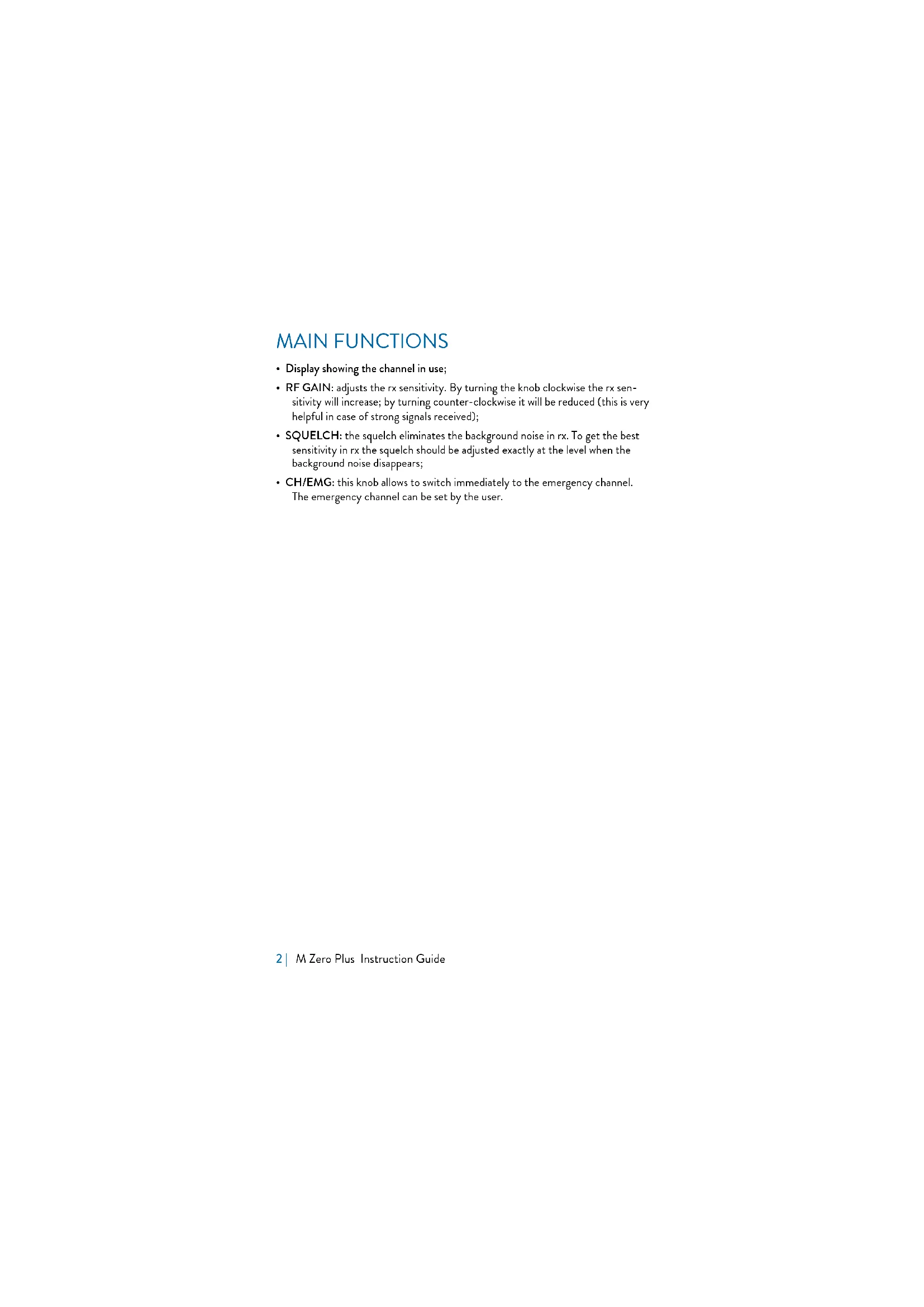
CONTROLS AND FUNCTIONS
- PIN mike connector: Connect the microphone to this jack;
- RF GAIN knob: Adjusts the receiver gain;
- SQUELCH knob: Adjusts the squelch threshold;
- ON/OFF-VOLUME selector: turn the knob to switch on/off the radio and to adjust the volume at the desired level;
- UP/DOWN controls: push the buttons to select the desired channel;
- Channel display: it shows the channel in use;
- TX led: the led lights up when you push the PTT button on the microphone;
- CH-EMG: Channel in use /Emergency channel. This selector allows to switch quickly between the emergency channel and the channel in use;
- AM/FM selector: to select AM or FM modulation.
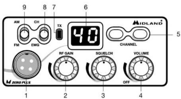
- Antenna coaxial connector SO239: connect here an antenna operating on 27 MHz;
- Power supply cable: insert the power cable with lighter plug into the vehicle's cigarette lighter cord.
- External speaker jack. If you connect an external speaker, the internal one is automatically excluded.
INSTALLATION
Safety and convenience are the primary consideration for mounting any piece of mobile equipment. All controls must be readily available to the operator without interfering with the movements necessary for safe operation of the vehicle. Be sure all cables are clear of the brake, clutch and accelerator. Also, thought must be given to the convenience and comfort of passengers.
Another extremely important requirement is the ease of installation and removal for those occasions when you might want to remove the unit for service and maintenance.
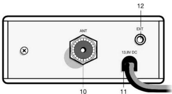
The most common mounting position for a transceiver is under the dashboard directly over the drive shaft hump. Do not mount the transceiver in the path of the heater or air conditioning air stream. Take your time and plan your installation carefully. When you have determined the best location for mounting, use the mounting bracket as a template to mark mounting holes. Take care when you drill the holes that you do not drill into wiring, trim or other accessories.
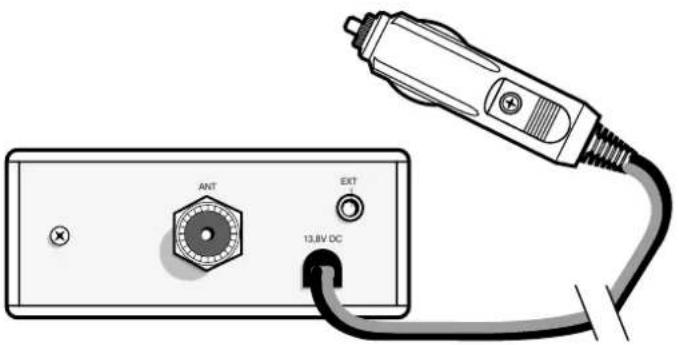
Mount in position with bolts, lock washers and nuts or self-threading screws. You can install this transceiver in any location where 12,6Vdc ± 10% power is available. Insert the power cable with lighter plug into the vehicle's cigarette lighter cord. Before operation, you must install and connect your antenna system. The lead from the antenna you've installed should be connected to the antenna coaxial connector. If you are using an external speaker, connect it to the EXT-SPKR jack.
REPLACING FUSE
If you replace the fuse for DC Power Cord, use 2 A type (one is supplied as spare). Hold the fuse holder and press on the inside, then rotate the holder.
Your transceiver has a new microphone connector. This ensures that you won't accidentally pull out or loosen the plug connection when moving the microphone cable out.
ANTENNA SYSTEM
A mobile antenna system is not limited only to the antenna. The transmission line as well as the vehicle are important factors in the total antenna system. Therefore, you must use the correct type of transmission line and mount the antenna securely in a position that will give you optimal results. Use coaxial cable with an impedance of 50 Ohms. We suggest type RG 58/U for lengths under 2.5m or RG 8/U for longer lengths. Generally speaking, you should keep the length of the transmission line to a minimum. The above discussion is as important for reception as for the transmission. If a mismatch exists between the antenna and the receiver, the excellent sensitivity and signal-to-noise ratio of the receiver circuit will be defeated.
Suggestions
A few general rules should help you to install any mobile antenna properly.
- Keep it as far as possible from the main bulk of the vehicle.
- During operation, it must be vertical, and rigid enough to remain vertical when the vehicle or boat is in motion.
- Mount it as far as possible from sources of noise (ignition system, gauges, etc.) and keep the transmission line away from these noise sources.
- An antenna mounted in a boat requires a good ground connection. This can be either a metal hull or a ground made of tin-foil or copper sheeting.
This ground should cover an area of at least 1 m2 or more. Be sure the transceiver also has an adequate ground. There are many types of mobile CB antennas: a full quarter-wave length whip, a centerloaded whip, top loaded whip and the base loaded type are typical. A vertically polarized whip antenna is best suited for mobile service. It is omnidirectional. If it's the loaded type, you will find it a physically shorter antenna. But, for greater efficiency the 2.5 m long, full quarter-wave whip is better. Antenna length is directly related to efficiency.
Generally, the longer it is, the more efficient will be.
There are many possible antenna locations on a car.
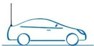
Four of the most popular are shown and discussed on the following. Roof Mount
In this position the antenna radiates equally in all directions. Since the normal 1/2 wavelength whip antenna is too long for roof mounting on a vehicle, the antenna is shortened and loading coil is used to provide the proper electrical length. Our fiberglass roof mount is a good durable antenna.
Front Cowl Mount
The radiation pattern is slightly greater in the direction of the rear fender opposite the side on which the antenna is mounted. However, the front position offers a number of advantages. The CB antenna can be easily mounted. It can double as both the CB and the standard auto radio an-
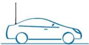
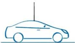
tenna by employing a two-way coupler. Ask about our complete line of antennas.
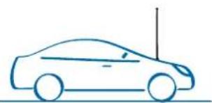
Rear Deck Mount
The radiation pattern is stronger in the direction of the front fender opposite the side on which the antenna is mounted. In this position you can use a full quarter-wave antenna or a shorter loaded whip. Here you might consider one of the full 2.5 meters whips.
Bumper Mount
The antenna radiates in a pattern directly in front of and to the rear of the vehicle, with maximum radiation directly away from the vehicle, in a horizontal plane. Despite its fairly irregular pattern, a bumpermounted full-length whip antenna will normally give the best results. Removing the antenna is simple and will leave no holes in the car.
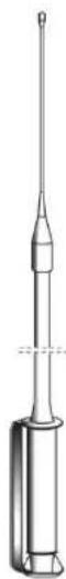
BASE STATION ANTENNA
While your Transceiver is designed for mobile operation, you might wish to use it as a base station unit, in conjunction with a 12,6 Vdc ± 10% 2 ADC power supply. If you decide to use your Transceiver as a base station, choose an antenna designed to operate most efficiently as a base station antenna. For example, the 1/2 wave antenna is a high-efficiency radiator with omnidirectional characteristics. It performs as well in most applications as the ground plane does. You can use this type of antenna for medium-long range communications.
USING YOUR TRANSCEIVER
Do not transmit without a suitable antenna or 50 Ohm load connected to the antenna connector.
To receive:
- Make sure that the cigarette lighter plug is properly inserted into a 12V power socket.
- Make sure that the antenna and the microphone are attached.
- The emergency knob must be set to the CH position.
- Set the Squelch control to maximum counterclockwise position.
- Turn on the unit by rotating the VOLUME control clockwise.
- Turn the RF-GAIN knob totally clockwise.
- Set channel selector to the desired channel.
- Adjust VOLUME for a suitable listening level.
- Adjust Squelch to cut out annoying background noise when no signal is being received.
To do this, set the Channel Selector to a channel where no signals are present or wait until signals cease on your channel. Then, rotate the Squelch control in a clockwise direction to the point where the background noise just stops. Now, when a signal is present, you will hear it, but will not be disturbed by noise on the channel between signals. When properly set, the Squelch keeps the receiver "dead" until a signal comes in on that channel. However, do not set the Squelch too high, or weak signals will not be able to open the Squelch circuit. To receive very weak signals, it is best to leave Squelch set to the minimum position by rotating the control maximum counter-clockwise. The Squelch circuit in your transceiver is an advanced design. It uses an operational amp IC to accomplish a hysteresis action. The result is that when you set the Squelch for a precise signal level, if that signal level increases or decreases in strength, the Squelch circuit will follow this change. With conventional Squelch circuit, often a signal which changes strength gets "chopped" by the Squelch circuit and you lose a portion of the message. With a hysteresis Squelch, you get it all.
To Transmit:
- Select the desired channel and the modulation (AM or FM).
- Press the push-to talk button on the microphone and hold it an angle about 5 - 7cm from your mouth and speak in a normal voice.
- To receive, release the push-to-talk button. Be sure the mic plug is firmly connected to the jack.
NOTE: shouting into the mic will not increase your power or signal. An internal circuit automatically sets the mic signal for maximum modulation, so speak loudly will give no advantage.
SELECTION OF Po/St BANDS
- Turn on the radio while keeping pressed the UP/DOWN controls
- With the UP / DOWN buttons select the desired band: Po = Poland (40 Ch AM/FM - 26.960/27.400) - St = Europe (40 CH AM/FM - 26.965/27.405)
- Push PTT to exit the selection
QUICK SCROLL
To scroll the channels, keep pressed the UP or DOWN controls for 6 seconds.
KEYPAD BEEP
When this function is enabled, you will hear a beep tone every time a button is pressed.
To activate/deactivate the beep tone:
- keep pressed the UP button while turning on the radio;
- press UP or DOWN to enable/disable the beep;
- when the beep tone is enabled, the display will show 'ON' and when it's disabled, 'OF' will be displayed.
EMERGENCY CHANNEL MEMORY
The emergency channel set by default is channel 19; to change it, follow these steps:
- move the knob of the CH/EMG selector to EMG position;
- the current emergency channel blinks on the display;
- press the UP / DOWN controls for 5 seconds at the same time. The display will stop blinking;
- with the UP/DOWN buttons select the new emergency channel;
- push again UP / DOWN for about 5 seconds;
- the display will blink again and will indicate the new emergency channel memory.
EXTERNAL SPEAKER
Connect a speaker with a power of 3-10 Watt to the EXT jack.
When you connect an external speaker to the radio, the internal speaker is automatically disconnected.
TECHNICAL SPECIFICATIONS
RECEIVER
Frequency coverage 26.965 to 27.405 MHz (Europe) 26.960 to 27.400 MHz (Poland)
Sensitivity better than 1.0~ V for 20 dB SINAD
Adjacent Channel Rejection .60 dB at 10 kHz; 70 dB for 20 KHz
Intermediate Frequency 1st IF=10.695 MHz; 2nd IF=455 KHz
Audio Output power 2 watts max
Frequency Response (6dB) 450-2500 Hz
Cross Modulation 45 dB or better
Squelch .adjustable from 1.2 V to 1mV
Duty cycle. 5/5/90
TRANSMITTER
Frequency coverage 26.965 to 27.405 MHz (Europe) 26.960 to 27.400 MHz (Poland)
Output Power 4 W
Type of modulation. AM/FM
Max modulation. 90% Max deviation. 1.9 KHz
Spurious Radiation 62 dB or better Frequency Tolerance better than 0.002%
Antenna impedance .50 Ohm Power supply 12,6 V ± 10%max
Max Current Drain. 2A
Dimensions 110x45x140 mm Weight .665 g
Specifications are subject to change without notice.
A readily accessible disconnect device shall be incorporated in the installation wiring.
The disconnect device shall disconnect both poles simultaneously.
HAUPTFUNKTIONEN 2
MEMORAREA UNUI CANAL DE URGENTA
Italy - Restrictions on the use - According to the Italian Frequency Allocation Table, issued on the G.U. No. 169 - Supplement 146 - of 20th July 2002 - note 49G, the standard in AM modulation needs a radiating system with a gain not higher than -6dB, such as, for example, with the antenna "PC8" with original cable.
Hereby Cte International Srl declares that this product is in compliance with the essential requirements and other relevant provisions of Directive 1999/5/ EC. The declaration of conformity is available on the web site www.midlandeurope.com
A/D/CH/FL
Produced or imported by:
CTE INTERNATIONAL s.r.l.
Via.R.Sevardi 7-42124 Mancasale Reggio
Emilia Italy
Imported by: ALAN-NEVADA UK
Unit1 Fitzherbert Spur Farlington Portsmouth
Hants. P061TT-United Kingdom
www.nevada.co.uk
The use of this transceiver can be subject to
national restrictions. Read the instructions
carefully before installation and use.
Importado por:
ALAN COMMUNICATIONS, S.A.