Excursion Mini EXM400 - Speaker YORKVILLE - Free user manual and instructions
Find the device manual for free Excursion Mini EXM400 YORKVILLE in PDF.

User questions about Excursion Mini EXM400 YORKVILLE
0 question about this device. Answer the ones you know or ask your own.
Ask a new question about this device
Download the instructions for your Speaker in PDF format for free! Find your manual Excursion Mini EXM400 - YORKVILLE and take your electronic device back in hand. On this page are published all the documents necessary for the use of your device. Excursion Mini EXM400 by YORKVILLE.
USER MANUAL Excursion Mini EXM400 YORKVILLE
Warning: To reduce the risk or fire or electric shock, do not expose this apparatus to rain or moisture. Do not
use this apparatus near water!
Warning: When using electric products, basic precautions should always be followed, including the following:
Power Sources Your unit should be connected to a power source only of the voltage specified in the owners manual or as marked on the unit. This unit has a polarized plug. Do not use with an extension cord or receptacle unless the plug can be fully inserted. Precautions should be taken so that the grounding scheme on the unit is not defeated. An apparatus with CLASS I construction shall be connected to a Mains socket outlet with a protective earthing ground. Where the MAINS plug or an appliance coupler is used as the disconnect device, the disconnect device shall remain readily operable. Hazards Do not place this product on an unstable cart, stand, tripod, bracket or table. The product may fall, causing serious personal injury and serious damage to the product. Use only with cart, stand, tripod, bracket, or table recommended by the manufacturer or sold with the product. Follow the manufacturer’s instructions when installing the product and use mounting accessories recommended by the manufacturer. Only use attachments/accessories specified by the manufacturer Note: Prolonged use of headphones at a high volume may cause health damage on your ears. The apparatus should not be exposed to dripping or splashing water; no objects filled with liquids should be placed on the apparatus. Te rminals marked with the “lightning bolt” are hazardous live; the external wiring connected to these terminals require installation by an instructed person or the use of ready made leads or cords. Ensure that proper ventilation is provided around the appliance. Do not install near any heat sources such as radiators, heat registers, stoves, or other apparatus (including amplifiers) that produce heat. No naked flame sources, such as lighted candles, should be placed on the apparatus. Power Cord Do not defeat the safety purpose of the polarized or grounding-type plug. A polarized plug has two blades with one wider than the other. A grounding type plug has two blades and a third grounding prong. The wide blade or the third prong are provided for your safety. If the provided plug does not fit into your outlet, consult an electrician for replacement of the obsolete outlet. The AC supply cord should be routed so that it is unlikely that it will be damaged. Protect the power cord from being walked on or pinched particularly at plugs. If the AC supply cord is damaged DO NOT OPERATE THE UNIT. To completely disconnect this apparatus from the AC Mains, disconnect the power supply cord plug from the AC receptacle. The mains plug of the power supply cord shall remain readily operable. Unplug this apparatus during lightning storms or when unused for long periods of time. Service The unit should be serviced only by qualified service personnel. Servicing is required when the apparatus has been damaged in any way, such as power-supply cord or plug is damaged, liquid has been spilled or objects have fallen into the apparatus, the apparatus has been exposed to rain or moisture, does not operate normally, or has been dropped. AVIS: AFIN DE REDUIRE LES RISQUE DE CHOC ELECTRIQUE, N’ENLEVEZ PAS LE COUVERT (OU LE PANNEAU ARRIERE) NE CONTIENT AUCUNE PIECE REPA RABLE PA R L’ UTILISATEUR. CONSULTEZ UN TECHNICIEN QUALIFIE POUR L’ENTRETIENT CE PRODUIT EST POUR L’USAGE À L’INTÉREUR SEULEMENT Instructions relatives au risque de feu, choc électrique, ou blessures aux personnes Veuillez Lire le Manuel: Il contient des informations qui devraient êtres comprises avant l’opération de votre appareil. Conservez. Gardez S.V.P. ces instructions pour consultations ultérieures et observez tous les avertissements. Nettoyez seulement avec le tissu sec. Emballage: Conservez la boite au cas ou l’appareil devait être retourner pour réparation. Avertissement: Pour réduire le risque de feu ou la décharge électrique, n'exposez pas cet appareil à la pluie ou à l'humidité. N’utilisez pas cet appareil près de l’eau! Attention: Lors de l’utilisation de produits électrique, assurez-vous d’adhérer à des précautions de bases incluant celle qui suivent: Alimentation L’ appareil ne doit être branché qu’à une source d’alimentation correspondant au voltage spécifié dans le manuel ou tel qu’indiqué sur l’appareil. Cet appareil est équipé d’une prise d’alimentation polarisée. Ne pas utiliser cet appareil avec un cordon de raccordement à moins qu’il soit possible d’insérer complètement les trois lames. Des précautions doivent êtres prises afin d’eviter que le système de mise à la terre de l’appareil ne soit désengagé. Un appareil construit selon les normes de CLASS I devrait être raccordé à une prise murale d’alimentation avec connexion intacte de mise à la masse. Lorsqu’une prise de branchement ou un coupleur d'appareils est utilisée comme dispositif de débranchement, ce dispositif de débranchement devra demeurer pleinement fonctionnel avec raccordement à la masse. Risque Ne pas placer cet appareil sur un chariot, un support, un trépied ou une table instables. L’appareil pourrait tomber et blesser quelqu’un ou subir des dommages importants. Utiliser seulement un chariot, un support, un trépied ou une table recommandés par le fabricant ou vendus avec le produit. Suivre les instructions du fabricant pour installer l’appareil et utiliser les accessoires recommandés par le fabricant. Utilisez seulement les attachements/accessoires indiqués par le fabricant Note: L'utilisation prolongée des écouteurs à un volume élevé peut avoir des conséquences néfastes sur la santé sur vos oreilles. . Il convient de ne pas placer sur l’appareil de sources de flammes nues, telles que des bougies allumées. L’appeil ne doit pas être exposé à des égouttements d’eau ou des éclaboussures et qu’aucun objet rempli de liquide tel que des vases ne doit être placé sur l’appareil. Assurez que lappareil est fourni de la propre ventilation. Ne procédez pas à l’installation près de source de chaleur tels que radiateurs, registre de chaleur, fours ou autres appareils (incluant les amplificateurs) qui produisent de la chaleur. Les dispositifs marqués d’une symbole “d’éclair” sont des parties dangereuses au toucher et que les câblages extérieurs connectés à ces dispositifs de connection extérieure doivent être effectivés par un opérateur formé ou en utilisant des cordons déjà préparés. Cordon d’Alimentation Ne pas enlever le dispositif de sécurité sur la prise polarisée ou la prise avec tige de mise à la masse du cordon d’alimentation. Une prise polarisée dispose de deux lames dont une plus large que l’autre. Une prise avec tige de mise à la masse dispose de deux lames en plus d’une troisième tige qui connecte à la masse. La lame plus large ou la tige de mise à la masse est prévu pour votre sécurité. La prise murale est désuète si elle n’est pas conçue pour accepter ce type de prise avec dispositif de sécurité. Dans ce cas, contactez un électricien pour faire remplacer la prise murale. Évitez d’endommager le cordon d’alimentation. Protégez le cordon d’alimentation. Assurez-vous qu’on ne marche pas dessus et qu’on ne le pince pas en particulier aux prises. N’UTILISEZ PA S L’APPAREIL si le cordon d’alimentation est endommagé. Pour débrancher complètement cet appareil de l’alimentation CA principale, déconnectez le cordon d’alimentation de la prise d’alimentation murale. Le cordon d’alimentation du bloc d’alimentation de l’appareil doit demeurer pleinement fonctionnel. Débranchez cet appareil durant les orages ou si inutilisé pendant de longues périodes. Service Consultez un technicien qualifié pour l’entretien de votre appareil. L'entretien est nécessaire quand l'appareil a été endommagé de quelque façon que se soit. Par exemple si le cordon d’alimentation ou la prise du cordon sont endommagés, si il y a eu du liquide qui a été renversé à l’intérieur ou des objets sont tombés dans l'appareil, si l'appareil a été exposé à la pluie ou à l'humidité, si il ne fonctionne pas normalement, ou a été échappé.S2125ACaution: hot surfaceAttention: surface chaudeIEC 60417-5041
IMPORTANT SAFETY INSTRUCTIONS (UL60065) FOLLOW ALL INSTRUCTIONS SUIVEZ TOUTES LES INSTRUCTIONS The Lightning Flash with arrowhead symbol within an equilateral triangle, is intended to alert the user to the presence of uninsulated "dangerous voltage" within the product enclosure that may be of sufficient magnitude to constitute a risk of shock to persons The exclamation point within an equilateral triangle is intended to alert the user to the presence of important operating and maintenance (servicing) instructions in the literature accompanying the product
1. Read these instructions. 2. Keep these instructions. 3. Heed all warnings. 4. Follow all instructions. 5. Do not use this apparatus near water. 6. Clean only with dry cloth.
7. Do not block any ventilation openings. Install in accordance with the manufacturer’s instructions.
8. Do not install near any heat sources such as radiators, heat registers, stoves, or other apparatus (including amplifiers) that produce heat. 9. Do not defeat the safety purpose of the polarized or grounding-type plug. A polarized plug has two blades with one wider than the other. A grounding type plug has two blades and a third grounding prong. The wide blade or the third prongs are provided for your safety. If the provided plug does not fit into your outlet, consult an electrician for replacement of the obsolete outlet. 10. Protect the power cord from being walked on or pinched particularly at plugs, convenience receptacles, and the point where they exit from the apparatus.
11. Only use attachments/accessories specified by the manufacturer.
12. Use only with the cart, stand, tripod, bracket, or table specified by the manufacturer, or sold with the apparatus. When a cart is used, use caution when moving the cart/apparatus combination to avoid injury from tip-over.
13. Unplug this apparatus during lightning storms or when unused for long periods of time.
14. Refer all servicing to qualified service personnel. Servicing is required when the apparatus has been damaged in any way, such as power-supply cord or plug is damaged, liquid has been spilled or objects have fallen into the apparatus, the apparatus has been exposed to rain or moisture, does not operate normally, or has been dropped. WARNING:
- To reduce the risk of fire or electric shock, do not expose this apparatus to rain or moisture and objects filled with liquids, such as vases, should not be placed on this apparatus.
- To completely disconnect this apparatus from the ac mains, disconnect the power supply cord plug from the ac receptacle.
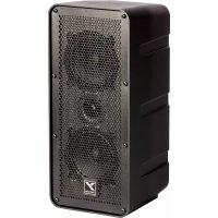
Introduction Welcome to the EXM400, a compact PA system designed to be portable and versatile. Designed with enough features to handle live performances and small DJ gigs, the EXM400 is great choice when a full sized PA may not be appropriate. Some features of the EXM400 include:
- Easy setup with internally wired speaker poles
- Scalable design allows system to grow to meet your needs
- Expandable with an additional pair of EXM400SAT satellite speakers
- Link port for connecting two EXM400 systems together
- Congurable for mono or stereo operation
- Bluetooth™ connection for streaming audio to the system
- Onboard 4-channel mixer with input settings for mic, guitar and line source
- DSP driven EQ and limiting
- Multiband limiting for increased system output
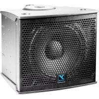
- 2 x 75 watt ampliers for the satellite speakers and 250 watts for the sub
- Clip LEDs on all critical signal inputs
- Balanced stereo line outputs This manual explains the various features and functions of the EXM400. For general information about mixing and other facets of sound-reinforcement check out our P.A. User Guide available on the internet... (http://www.yorkville.com). System Configurations The scalable nature of the EXM400 allows for several congurations that can be utilized to suit your needs. Here are some examples: SPKR OUT STEREO (Single System) STEREO (Two Systems) LINK STEREO (With Extension) SPKR OUT MONO (Single System) Use the EXM400SAT Extension Kit to double fullrange output!2 EXM Input Channel Features Channel 1
Channel 1 is equipped with a phone/XLR combi jack, either balanced or unbalanced ¼-inch and XLR male cables may be used. For powering condenser microphones, 24V of phantom power is present on the XLR input jack. Although the phantom power is not defeatable, it will not damage dynamic microphones connected with a balanced XLR cable.
2. Input Select Button
The input select button is used to congure Channel 1 for either guitar or microphone. Individual changes to the internal EQ, gain and limiting are made to match the input source selected. In the event the input signal induces clipping, both sides of the input select button will illuminate red. Reduce the output level at your source to prevent further clipping.
The EXM400 features active channel input circuitry with exceptionally high audio headroom. The Level control adjusts the channel gain over an 85 dB range. Use this control to adjust the chan- nel’s level in the overall system mix.
Channel 1 is equipped with a single tone control which functions as a tilt EQ. When centered, the tone control is bypassed, allowing the signal to pass through the channel unaltered. Turn- ing the control clockwise will increase treble and reduce bass. Going counter-clockwise, bass will increase and treble will drop. The tone control can be useful for enhancing the sound of your signal but it can also be handy for taming feedback in microphones and guitars. If you are encountering high frequency feedback, turn the control counter-clockwise. If low frequency feedback is occurring (as is common with acoustic guitars), turn the control clockwise.
A hall reverb is available on Channel 1 and 2. Use the reverb control to mix in some additional am- biance to your signal. This often works well with guitar and vocals. Channel 2
Channel 2 is equipped with a phone/XLR combi jack, either balanced or unbalanced ¼-inch and XLR male cables may be used. For powering condenser microphones, 24V of phantom power is present on the XLR input jack. Although the phantom is not defeatable, it will not damage dy- namic microphones connected with a balanced XLR cable.
2. Input Select Button
The input select button is used to congure Channel 2 for either line level or microphone. Individu- al changes to the internal EQ, gain and limiting are made to match the input source selected. In the event the input signal induces clipping, both sides of the input select button will illuminate red. Reduce the output level at your source to prevent further clipping.
The EXM400 features active channel input circuitry with exceptionally high audio headroom. The Level control adjusts the channel gain over an 85 dB range. Use this control to adjust the channel’s level in the overall system mix.
Channel 2 is equipped with a single tone control which functions as a tilt EQ. When centered, the tone control is bypassed, allowing the signal to pass through the channel unaltered. Turn- ing the control clockwise will increase treble and reduce bass. Going counter-clockwise, bass will increase and treble will drop. The tone control can be useful for enhancing the sound of your signal but it can also be handy for taming feedback when using a microphone. If you are encountering high frequency feedback, turn the control counter-clockwise. If low frequency feedback is occurring, turn the control clockwise. Max Min MaxMinInput 1 Max Min MaxMinInput 2EXM
A hall reverb is available on Channel 1 and 2. Use the reverb control to mix in some additional am- biance to your signal. This often works well with vocals. Channel 3/4
Line level signals can be connected to either of the TRS phone jacks or the 1/8-inch stereo input jack on Channel 3/4. The 1/4-inch jacks can accept either balanced or unbalanced signals. If only one of the 1/4-inch jacks is used, the channel self congures for mono playback. If a stereo source is connected but the EXM400 is setup in a mono configuration, the signal from Channel 3/4 will automatically be summed to mono.
The EXM400 features active channel input circuitry with exceptionally high audio headroom. The Level control adjusts the channel gain over an 85 dB range. Use this control to adjust the chan- nel’s level in the overall system mix.
Channel 3/4 is equipped with a pair of tone controls for enhancing the channel’s signal. The treble and bass controls allow for a +/- 6 dB adjustment at 2000 and 110 Hz respectively. When placed at the center position, these controls are bypassed. Bluetooth™ Section The EXM400 is capable of receiving streaming audio over Bluetooth™ from devices such as smartphones and laptops. Pairing your device with the EXM400 is simple and gives you the free- dom to play your music wirelessly.
1. Pairing / Bluetooth™ Enable Button
When the Enable Button is depressed, the Bluetooth™ audio connection is available for pairing. Con- versely, to block incoming connections or break a current connection, switch to the off position. With the Enable Button depressed, go to the Bluetooth™ menu on your streaming audio device. You will see a device named “YS-####” where #### indicates a four digit number unique to your EXM400. Select this device to initiate pairing. Once you see the “YS-####” device connected, you will be able to stream audio to the EXM400.
2. Bluetooth™ Status Indicator
The blue status indicator alerts the user to the current status of the Bluetooth™ connection. A fast blinking light indicates an available, unpaired connection. Clusters of three short bursts mean there is an active connection. No light means that Bluetooth™ is disabled or a connection has been lost.
3. Bluetooth™ Level Control
Use this control to set the audio level for the Bluetooth™ connection. Level can also be controlled directly at your streaming device. The EXM400’s Bluetooth™ operating range is rated for 10 meters (33 feet) line of sight. The quality of the link can be affected by an excess of traffic in the 2.4 GHz bandwidth or structures between the EXM400 and the streaming device. Master Section
Use the Master Control to set the overall level of the EXM400. This control sets the output of both the satellites and the subwoofer. When two systems are linked together, the Master Control only affects the level of the unit it resides on.
The sub control sets the relative level of the subwoofer to the satellite speakers. Typically, this control should be set to noon. If an additional pair of EXM400SAT speakers is being used, you may want to turn this control up. If you are using microphones and acoustic guitars and do not need much bass, turn the Sub level down to prevent low frequency feedback. Max Min Clip Line 3/4STEREOBALBluetooth
The Limit Indicator will begin to ash red when the internal limiter starts to engage. The limiter automatically lowers the level of the system to prevent the audio from clipping. The EXM400 is at its loudest when the Limit Indicator is ickering. Turning up the level further will not increase the system output considerably and will result in a compressed sound. Turn the Master Level down to reduce limiting Line Out Jacks You will nd a pair of balanced, ¼-inch output jacks below the Master Section. These jacks provide a line level stereo signal of the input channels and Bluetooth™ connection. Use these jacks to con- nect to recording gear, a larger PA or any other outboard gear. Link Section In situations where additional bass or input channels are required, two EXM400 systems can be linked together. This offers the possibility for 2 subs, up to 8 satellites speakers and 8 mixer channels.
To utilize the link feature of the EXM400, insert a ¼-inch TRS cable into the Link Jack of the two systems. Use of a non-TRS cable will result in loss of a stereo channel.
2. Unit Assign Button
When linking a pair of EXM400 systems, each unit must be assigned to the left or right side. After connecting the two systems with a TRS cable via the Link Jack, assign the system on the right to the right channel (button in, red light) and the other system to the left (button out, green light). Assigning both systems to the same channel will result in a non-functioning link. Speaker Out / Stereo Operation When congured with both satellite speakers on the sub-mounted poles, the EXM400 internally sums any stereo signals to mono. Stereo output is only achieved when two systems are linked to- gether or the Speaker Out Jack is used.
In order to achieve stereo output with a single EXM400 system, connect the supplied ¼-inch speaker cable between the Speaker Out Jack and the ¼-inch jack on a satellite speaker. This inter- nally switches the output of the sub-mounted satellites from mono summed stereo to left channel output. The speakers attached to the Speaker Out will produce the right channel. As with speakers connected to the top of the subwoofer, the Speaker Out Jack is capable of driv- ing two satellite speakers max. Full system power is achieved when two satellites are placed on the subwoofer and an additional two satellites are connected to the Speaker Out Jack.
2. Microphone Stand Adapter
Included with the EXM400 is an adapter to mount satellite speakers on a standard microphone stand. Simply thread the adapter to a 5/8-inch thread mic stand and place your satellite speakers on the adapter. NOTE: If the user wishes to run a stereo system with the subwoofer in the middle, a standard banana to ¼-inch speaker cable can be used to connect the left channel speakers to the port on the top of the subwoofer. BALNote: Make sure that one system is assigned Left and the other Right. LINK STEREO(TWO SYSTEMS)Unit Assign SPKR OUT STEREO(WITH EXTENSION)Use the EXM400SATExtension Kit todouble fullrange output!
1/4-inch T.R.S. Phone Plug Balanced 1/4-inch T.R.S. to Balanced XLR XLR Plug (Male) Tip = 0° Ring = 180° Sleeve = Ground
Specifications Model EXM400 System Type Compact PA Active or Passive Active Program Power (watts)
block-diagram-EXM400-00-1v0.aiThis equipment has been tested and found to comply with the limits for a Class B digital device, pursuant to part 15 of the FCC Rules. These limits are designed to provide reasonable protection against harmful interference in a residential installa- tion. This equipment generates, uses and can radiate radio frequency energy, and if not installed and used in accordance with the instructions, may cause harmful interference to radio communications. However, there is no guarantee that interfer- ence will not occur in a particular installation. If this equipment does cause harmful interference to radio or television reception, which can be determined by turning the equipment off and on, the user is encouraged to try to correct the interference by one or more of the following measures:
- Reorient or relocate the receiving antenna.
- Increase the separation between the equipment and receiver.
- Connect the equipment into an outlet on a circuit different from that to which the receiver is connected.
Voice: (905) 837-8481 Fax: (905) 837-8746 Manual-Owners-exm400-1v2 • February 13, 2017