
EXM Mobile 12 - Loudspeaker YORKVILLE - Free user manual and instructions
Find the device manual for free EXM Mobile 12 YORKVILLE in PDF.
| Product Type | Portable active speaker with built-in mixer |
| Brand | Yorkville |
| Model | EXM Mobile 12 |
| Power Supply | Mains 100-240V AC or built-in rechargeable lithium-ion battery |
| Battery | Rechargeable lithium-ion, charging via LED indicator (green: charged, red: charging) |
| Number of Input Channels | 3 channels |
| Input Types | Channels 1 & 2: combo XLR (mic) / 1/4" jack (line or instrument); Channel 3: XLR (mic), 1/8" stereo jack (multimedia), and Bluetooth |
| Phantom Power | 12V on XLR inputs for condenser microphones |
| Bluetooth | Audio streaming from any compatible device; pairing via Pairing button (4s) |
| Built-in Effects | Delay, Hall Reverb, Room Reverb; selector with OFF position |
| Per-channel Shape Control | Music, Speech, or flat (center position) |
| Link Function | Links multiple EXM Mobile speakers via XLR cable; all channels are shared |
| Battery Status Indicators | 4 LEDs: green (85%+), green, yellow, flashing red (~10%) |
| Sleep Mode | Automatic to save battery; configurable via gain settings |
| Charging Temperature | 0°C to 45°C; does not charge outside this range |
| Cleaning | With a dry cloth only |
| Use | Indoor only; do not expose to rain or moisture |
| Safety Class | CLASS II (double insulation) |
| Included Accessories | Power cord |
| Service and Maintenance | Refer all servicing to qualified personnel; do not open |
Frequently Asked Questions - EXM Mobile 12 YORKVILLE
User questions about EXM Mobile 12 YORKVILLE
0 question about this device. Answer the ones you know or ask your own.
Ask a new question about this device
Download the instructions for your Loudspeaker in PDF format for free! Find your manual EXM Mobile 12 - YORKVILLE and take your electronic device back in hand. On this page are published all the documents necessary for the use of your device. EXM Mobile 12 by YORKVILLE.
USER MANUAL EXM Mobile 12 YORKVILLE

WEB: www.yorkville.com
WORLD HEADQUARTERS
CANADA
Yorkville Sound Limited
550 Granite Court
Pickering, Ontario
L1W 3Y8 CANADA
Voice: 905-837-8481
Fax: 905-837-8746
U.S.A.
Yorkville Sound Inc.
4625 Witmer Industrial Estate
Niagara Falls, New York
14305, USA
Voice: 716-297-2920
Fax: 716-297-3689
Quality and Innovation Since 1963
Printed in Canada

SERVICE MANUAL
EXM Mobile 12
SMT Disclaimer
Due to the complex nature of the use of SMT installed components in Yorkville equipment, we highly caution all service technicians in attempting to repair or replace SMT factory installed components.
Many of these components may be glued prior to initial soldering
Replacing SMT components requires expensive
specialized de-soldering equipment and training
Yorkville Sound will repair and replace defective SMT components to ensure proper quality assurance and installation is maintained.
IMPORTANT SAFETY INSTRUCTIONS

This lightning flash with arrowhead symbol, within an
equilateral triangle, is intended to alert the user to the presence of uninsulated "dangerous voltage" within the product's enclosure that may be of sufficient magnitude to constitute a risk of electric shock to persons.
The DO NOT STACK symbol is inlanded to alert the user that the product shall not be vertically slacked because of the nature of the product.
The excitation point within an equilateral triangle is intended to alert the user to the presence of important operating and maintenance (servicing) instructions in the literature accompanying the appliance.
Instructions pertaining to a risk of fire, electric shock, or injury to a person
CAUTION: TO REDUCE THE RISK OF ELECTRIC SHOCK, DO NOT REMOVE COVER (OR BACK). NO USER SERVICEABLE PARTS INSIDE. REFER SERVICING TO QUALIFIED SERVICE
PERSONNEL. THIS DEVICE IS FOR INDOOR USE ONLY!
INSTALLED BATTERY PACKS SHALL NOT BE EXPOSED TO EXCESSIVE HEAT SUCH AS SUNSHINE, FIRE OR THE LIKE.
Read Instructions: The Owner's Manual should be read and understood before operation of your unit. Please, save these instructions for future reference and heed all warnings.
Cleaning: Clean only with dry cloth.
Packaging: Keep the box and packaging materials, in case the unit needs to be returned for service.
Warning: To reduce the risk or fire or electric shock, do not expose this apparatus to rain or moisture. Do not use this apparatus near water!
Warning: When using electric products, basic precautions should always be followed, including the following:
Power Sources
Your unit should be connected to a power source only of the voltage specified in the owners manual or as marked on the unit. This unit has a polarized plug. Do not use with an extension cord or receptacle unless the plug can be fully inserted. Precautions should be taken so that the grounding scheme on the unit is not defeated. An apparatus with CLASS I construction shall be connected to a Mains socket outlet with a protective earthing connection. Where the MAINS plug or an appliance coupler is used as the disconnect device, the disconnect device shall remain readily operable.
Hazards
Do not place this product on an unstable cart, stand, tripod, bracket or table. The product may fail, causing serious personal injury and serious damage to the product. Use only with cart, stand, tripod, bracket, or table recommended by the manufacturer or sold with the product. Follow the manufacturer's instructions when installing the product and use mounting accessories recommended by the manufacturer. Only use attachments/absaccessories specified by the manufacturer.
Equipment that is suspended overhead must use a secondary safeguard to prevent personal injury in the event the primary mounting mechanism fails. Safety eyebolts attached to the equipment and galvanized steel wire can be used together to implement a fallsafe mounting thus ensuring the safety of the equipment and anyone positioned below the equipment.
Improper installation can result in bodily injury or death. If you are not qualified to attempt the installation get help from a professional structural rigger. Notes: Prolonged use of headphones at a high volume may cause health damage to your ears.
The apparatus should not be exposed to dripping or splashing water; no objects filled with liquids should be placed on the apparatus.
Terminals marked with the "lightning bolt" are hazardous live; the external wiring connected to these terminals require installation by an instructed person or the use of ready made leads or cords.
Ensure that proper ventilation is provided around the appliance. Do not install near any heat sources such as radiators, heat registers, sloves, or other apparatus (including amplifiers) that produce heat.
No naked flame sources, such as lighted candles, should be placed on the apparatus.
Power Cord
Do not defeat the safety purpose of the polarized or grounding-type plug. A polarized plug has two blades with one wider than the other. A grounding type plug has two blades and a third grounding prong. The wide blades or the third prong are provided for your safety. If the provided plug does not fill into your outlet, consult an electrician for replacement of the obsolete outlet. The AC supply cord should be routed so that it is unlikely that it will be damaged. Protect the power cord from being walked on or pinched particularly at plugs. If the AC supply cord is damaged DO NOT OPERATE THE UNIT. To completely disconnect this apparatus from the AC Mains, disconnect the power supply cord plug from the AC receptacle. The mains plug of the power supply cord shall remain readily operable.
Unplug this apparatus during lightning storms or when unused for long periods of time.
Service
The unit should be serviced only by qualified service personnel. Servicing is required when the apparatus has been damaged in any way, such as power-supply cord or plug is damaged, liquid has been spilled or objects have fallen into the apparatus, the apparatus has been exposed to rain or moisture, does not operate normally, requires battery pack replacement or has been dropped. Disconnect power before servicing!
IMPORTANT SAFETY INSTRUCTIONS

The Lightning Flash with arrowhead symbol within an equilateral triangle, is intended to alert the user to the presence of uninsulated "dangerous voltage" within the product enclosure that may be of sufficient magnitude to constitute a risk of shock to persons

The exclamation point within an equilateral triangle is intended to alert the user to the presence of important operating and maintenance (servicing) instructions in the literature accompanying the product
-
Read these instructions.
-
Keep these instructions.
-
Head all warnings.
-
Follow all instructions.
-
Do not use this apparatus near water.
-
Clean only with dry cloth.
-
Do not block any ventilation openings. Install in accordance with the manufacturer's instructions.
-
Do not install near any heat sources such as radiators, heat registers, stoves, or other apparatus (including amplifiers) that produce heat.
-
Do not defeat the safety purpose of the polarized or grounding-type plug. Apolarized plug has two blades with one wider than the other. A grounding type plug has two blades and a third grounding prong. The wide blade or the third prongs are provided for your safety. If the provided plug does not fit into your outlet, consult an electrician for replacement of the obsolete outlet.
-
Protect the power cord from being walked on or pinched particularly at plugs, convenience receptacles, and the point where they exit from the apparatus.
-
Only use attachments/accessories specified by the manufacturer.
-
Use only with the cart, stand, tripod, bracket, or table specified by the manufacturer, or sold with the apparatus. When a cart is used, use caution when moving the cart/apparatus combination to avoid injury from lip-over.
-
Unplug this apparatus during lightning storms or when unused for long periods of time.
-
Refer all servicing to qualified service personnel. Servicing is required when the apparatus has been damaged in any way, such as power-supply cord or plug is damaged, liquid has been spilled or objects have fallen into the apparatus, the apparatus has been exposed to rain or moisture, does not operate normally, or has been dropped.
WARNING:
• To reduce the risk of fire or electric shock, do not expose this apparatus to rain or moisture and objects filled with liquids, such as vases, should not be placed on this apparatus.
• To completely disconnect this apparatus from the ac mains, disconnect the power supply cord plug from the ac receptacle.
- The mains plug of the power supply cord or appliance coupler shall remain readily accessible.

POUR PRÉVENIR LES RISQUES D'ÉLECTROCUTION,
NE PAS RACCORDER A L'ALIMENTATION ÉLECTRIQUE ALORS QUE LA GRILLE EST RETIRÉE.


| Specifications | |||
| EXM 70 EXM Mobile EXM Mobile12 | |||
| Program Power (watts) | 60 watts 60 watts 60 watts | ||
| Max SPL (dB) | 115 115 120 Continuous (126 Peak) | ||
| Frequency Response (Hz +/- 3db) | 90-20k 70-20x 65-18k | ||
| Speaker Configuration - LF | 2 x 6.5-inch (2 x 5-inch pre-2020) 2 x 6.5-inch 12 inch | ||
| Speaker Configuration - HF | 1-inch Soft Dome 1-inch Soft Dome 1 inch exit compression driver | ||
| Inputs | 3 3 3 | ||
| Channel 1 Input | XLR / 1⁄4-inch Combi-jack | XLR / 1⁄4-inch Combi-jack | XLR / 1⁄4-inch Combi-jack |
| Channel 1 Controls | Level, Shape, Effects Send | Level, Shape, Effects Send | Level, Shape, Effects Send |
| Channel 2 Input | XLR / 1⁄4-inch Combi-jack | XLR / 1⁄4-inch Combi-jack | XLR / 1⁄4-inch Combi-jack |
| Channel 2 Controls | Level, Shape, Effects Send | Level, Shape, Effects Send | Level, Shape, Effects Send |
| Channel 3 Input | XLR Mic & 1/8-inch TRS Stereo Jack, BluetoothTM | XLR Mic & 1/8-inch TRS Stereo Jack, BluetoothTM | XLR Mic & 1/8-inch TRS Stereo Jack, BluetoothTM |
| Channel 3 Controls | Level, Shape, Effects Send, Bluetooth | Level, Shape, Effects Send, BluetoothTM | Level, Shape, Effects Send, BluetoothTM |
| Master Volume Control | Yes Yes | Yes | |
| Link In/Out (type / configuration) | XLR Connector (Male and Female) | XLR Connector (Male and Female) | XLR Connector (Male and Female) |
| LED Indicators | Power, Clip (CH1, CH2, CH3), Bluetooth | Power, Clip (CH1, CH2, CH3), Bluetooth, 4x Battery Level, Charging Status | Power, Clip (CH1, CH2, CH3), Bluetooth, 4x Battery Level, Charging Status |
| Other Features | Digital Effects (Hall Reverb, Room Reverb and Delay) | Digital Effects (Hall Reverb, Room Reverb and Delay) | Digital Effects (Hall Reverb, Room Reverb and Delay) |
| Power Consumption while charging (watts) | N/A | 32 (battery fully discharged and unit idle) | 32 (battery fully discharged and unit idle) |
| Dimensions (DWH, inches) | 8 x 7.75 x 17.5 | 8 x 7.75 x 17.5 | 23.5 x 13.5 x 11.5 |
| Dimensions (DWH, cm) | 20.25 x 19.7 x 44.5 | 20.25 x 19.7 x 44.5 | 59.5 x 34 x 29 |
| Weight (lbs/kg) | 16.3 / 7.4 (14.4 / 6.5 pre-2020) | 17.8 / 8.0 | 33.4 / 15.1 |
Specifications subject to change without notice
Spécifications
| EXM 70 EXM MOBILE EXM Mobile12 | |||
| Puissance programme (watts) | 60 watts 60 watts | 60 watts | |
| Max SPL (dB) | 115 115 | 120dB Continuous (128 Peak) | |
| Réponse en Fréquence (Hz +/- 3dB) | 90-20k 70-20k 65-18k | ||
| Configuration haut-parleur - Entrées | 2 x 6.5-pouce (2 x 5-pouce avant-2020) | 2 x 6.5-pouce | 12-pouce |
| Configuration des haut-parleurs - HF | Dôme souple de 1 pouce Dôme souple de 1 pouce | Dôme souple de 1 pouce | |
| Entrées | 3 | 3 | 3 |
| Entrée du canal 1 | XLR / 1⁄4 de pouce Combi-jack XLR / 1⁄4 de pouce Combi-jack | XLR / 1⁄4 de pouce Combi-jack | |
| Commande du canal 1 | Level, Shape, Effects | Level, Shape, Effects | Level, Shape, Effects |
| Entrée du canal 2 | XLR / 1⁄4 de pouce Combi-jack XLR / 1⁄4 de pouce Combi-jack | XLR / 1⁄4 de pouce Combi-jack | |
| Commande du canal 2 | Level, Shape, Effects Send Level, Shape, Effects Send | Level, Shape, Effects Send | |
| Entrée du canal 3 | XLR et Jack stéréo 1/8-pouce stéréo, BluetoothTM XLR et Jack stéréo 1/8-pouce stéréo, BluetoothTM | XLR et Jack stéréo 1/8-pouce stéréo, BluetoothTM | |
| Commande du canal 3 | Level, Shape, Effects, Bluetooth Level, Shape, Effects, BluetoothTM | Level, Shape, Effects, BluetoothTM | |
| Master Volume Control | Oui Oui | Oui | |
| Entrée / Sortie Link (type / configuration) | Connecteur XLR Connecteur XLR | XLR Connector (Male and Female) | |
| Indicateurs DEL | Alimentation, Clip (CH1, CH2, CH3), Bluetooth,Niveau de batterie 4x, État de charge | Power, Clip (CH1, CH2, CH3), Bluetooth, 4x Ballary Level,Chardine Status | |
| Autres caractéristiques | Effets numériques (Hall Reverb, Room Reverb and Delay) | Effets numériques (Hall Reverb, Room Reverb and Delay) | Effets numériques (Hall Reverb, Room Reverb and Delay) |
| Consommation pendant la charge (watts) | N/A | 32 (batterie complément déchargée et au repos) | 32 (batterie complément déchargée et au repos) |
| Dimensions (PLH, pouces) | 8 x 7.75 x 17.5 | 8 x 7.75 x 17.5 | 23.5 x 13.5 x 11.5 |
| Dimensions (DWH, cm) | 20.25 x 19.7 x 44.5 | 20.25 x 19.7 x 44.5 | 59.5 x 34 x 29 |
| Poids (lb / kg) | 16.3 / 7.4 (14.4 / 6.5 avant-2020) | 17.8 / 8.0 | 33.4 / 15.1 |
Block Diagram - EXM 70, EXM Mobile & Mobile12
DESIGNED & MANUFACTURED BY YORKVILLE SOUND

flowchart
graph TD
    subgraph Channel 1
        A["Line 1/4-inch"] --> B["Combi Jack"]
        B --> C["+24V Phantom Power"]
        C --> D["Limit"]
        D --> E["CLIP Level"]
        E --> F["Shape"]
        F --> G["EFX"]
    end

    subgraph Channel 2
        H["Line 1/4-inch"] --> I["Combi Jack"]
        I --> J["+24V Phantom Power"]
        J --> K["Limit"]
        K --> L["CLIP Level"]
        L --> M["Shape"]
        M --> N["EFX"]
    end

    subgraph Channel 3
        O["Mic XLR"] --> P["Line 3.5mm"]
        P --> Q["+24V Phantom Power"]
        Q --> R["CLIP Level"]
        R --> S["ShapeLevel"]
        S --> T["EFX"]
    end

    subgraph Link
        U["Mic XLR"] --> V["Link"]
        W["Mic XLR"] --> X["Link"]
    end

    D --> Y["Master"]
    M --> Y
    T --> Y
    Y --> Z["HPF 81 Hz"]
    Z --> AA["Limit"]
    AA --> AB["NPF"]
    AB --> AC["PVR AMP"]
    AC --> AD["EXM70 / EXMMOBILE / MOBILE12 1-Inch EXIT HF Driver"]

    subgraph Channel 4
        AE["Line 1/4-inch"] --> AF["Combi Jack"]
        AF --> AG["+24V Phantom Power"]
        AG --> AH["CLIP Level"]
        AH --> AI["Shape"]
        AI --> AJ["EFX"]
    end

    subgraph Channel 5
        AK["Line 3.5mm"] --> AL["Bluetooth™ Radio"]
        AL --> AM["CLIP Level"]
        AM --> AN["ShapeLevel"]
    end

    subgraph Channel 6
        AO["Mic XLR"] --> AP["Line 3.5mm"]
        AP --> AQ["+24V Phantom Power"]
        AQ --> AR["CLIP Level"]
        AR --> AS["ShapeLevel"]
    end

    subgraph Channel 7
        AT["Mic XLR"] --> AU["Line 3.5mm"]
        AU --> AV["+24V Phantom Power"]
        AV --> AW["CLIP Level"]
        AW --> AX["ShapeLevel"]
    end

    subgraph Channel 8
        AY["Mic XLR"] --> AZ["Line 3.5mm"]
        AZ --> BA["+24V Phantom Power"]
        BA --> BB["CLIP Level"]
        BB --> BC["ShapeLevel"]
    end

    subgraph Channel 9
        DA["Mic XLR"] --> DB["Line 3.5mm"]
        DB --> DC["+24V Phantom Power"]
        DC --> DD["CLIP Level"]
        DD --> DE["ShapeLevel"]
    end

    subgraph Channel 10
        DF["Mic XLR"] --> DG["Line 3.5mm"]
        DG --> DH["+24V Phantom Power"]
        DH --> DI["CLIP Level"]
        DI --> DJ["ShapeLevel"]
    end

    subgraph Channel 11
        DE --> DE
        D --> EF["Mic XLR"] & AF
    end

    subgraph Channel 12
        GF["Mic XLR"] & AG["Mic XLR"] & AH["Mic XLR"] & AI["Mic XLR"] & AJ["Mic XLR"] & AK["Mic XLR"] & AL["Mic XLR"] & AM["Mic XLR"] & AN["Mic XLR"] & AO["Mic XLR"] & AP["Mic XLR"] & AQ["Mic XLR"] & AR["Mic XLR"] & AS["Mic XLR"] & AT["Mic XLR"] & AU["Mic XLR"] & AV["Mic XLR"] & AW["Mic XLR"] & AX["Mic XLR"] & AY["Mic XLR"] & AZM["Mic XLR"] & BA["Mic XLR"] & BB["Mic XLR"] & BC["Mic XLR"] & DA["Mic XLR"] & AE["Mic XLR"] & AFM["Mic XLR"] & AGM["Mic XLR"] & AHM["Mic XLR"] & AIH["Mic XLR"] & AJI["Mic XLR"] & AKI["Mic XLR"] & ALI["Mic XLR"] & ANJ["Mic XLR"] & AOJ["Mic XLR"] & APJ["Mic XLR"] & AYJ["Mic XLR"] & AYK["A/B/C/D"]
M1814 Parts Reference List 3/5/2020
| REF | YS # | Description | REF | YS # | Description | REF | YS # | Description | REF | YS # | Description | REF | YS # | Description |
| 1 | W184 69 | EMANOBIL512 INPUT BOARD | 092 | 5631 | 22U | 50V 29CAP TAR 0X7MM 2EL | A | 4154 14XLR PCB MT VERT ACJCAVZL | P31a | W100 | INC 1% | 800S SMT RES | 01a | W100 5408 1% 000S BMT RES |
| 2 | 5256 47 | 80V 29CAP TAR 0X7MM 2LL | 095 | 10UN | 100V 10CAP | 120S SMT XTR | A | 4152 14XHWAR PCB MT VERT ACJCAVZL | P31c | W100 | INC 1% | 800S SMT RES | 01c | W100 3408 1% 000S BMT RES |
| 3 | 5631 22 | 80V 29CAP TAR 0X7MM 2LL | 096 | 10UN | 50V 5NCAP | 000S SMT XTR | B | 4010 XLR LMLPCD MT VERT 24MM AA-SCHES | P31d | W100 | 26K 1% | 800S SMT RES | 01d | W128 9625 1% 000S BMT RES |
| 4 | 5631 22 | 80V 29CAP TAR 0X7MM 2HL | 097 | 10UN | 50V 5NCAP | 000S SMT XTR | B | 4218 35MV ZOR PCB MT V ST SMI SMT-3TE | P31e | W100 | 27K 1% | 800S SMT RES | 01e | W128 8025 1% 000S BMT RES |
| 5 | 5631 22 | 80V 29CAP TAR 0X7MM 2HL | 098 | 10UN | 50V 5NCAP | 000S SMT XTR | B | 4140 XLR VALVE PCB MT VERT 24MM AA-SCHES | P31a | W100 | 10K 1% | 800S SMT RES | 01a | W128 8025 1% 000S BMT RES |
| 6 | 5631 22 | 80V 29CAP TAR 0X7MM 2LL | 099 | 10UN | 50V 5NCAP | 000S SMT XTR | B | RED LED 1V5 20VA 120S SMT | P31b | W100 | 10K 1% | 800S SMT RES | 01b | W128 4099 1% 000S BMT RES |
| 7 | 5631 22 | 80V 29CAP TAR 0X7MM 2FL | 100 | 10UN | 50V 5NCAP | 000S SMT XTR | A | RED LED 1V5 20VA 120S SMT | P31c | W100 | 24K6 1% | 800S SMT RES | 01c | W100 4409 1% 000S BMT RES |
| 8 | 150V | 50V 5NCAP 120G SMT XTR | 0102 | 10UN | 100V 10CAP | 120S SMT XTR | AUC | RED LED 1V5 20VA 120S SMT | P31d | W100 | 24K6 1% | 800S SMT RES | 01d | W100 1300 1% 000S BMT RES |
| 9 | 150V | 50V 5NCAP 120G SMT XTR | 0105 | 5212 | 10UN | 100V 5NCAP TAR 2AD 2FLM | A3 | RDGSN LLD 1V7 20MA 000S SMT | P32a | W100 | 27K4 1% | 800S SMT RES | 01b | W100 4738 1% 000S SMT RES |
| 10 | 30V | 50V 5NCAP 000S SMT XTR | 0106 | 5264 | 1U | 63V 29CAP TAR 0X7MM 2LL | A4 | YLL LLD 1V7 20MA 120S SMT | P32b | W100 | 27K4 1% | 800S SMT RES | 01b | W100 4738 1% 000S SMT RES |
| 11 | 3320 22 | 80V 5NCAP 000S SMT XPO | 0114 | 10UN | 50V 5NCAP | 000S SMT XTR | A5 | BLI LLD 1V5 20VA 120S SMT | P32c | W100 | 19K6 1% | 800S SMT RES | 01c | W100 1101 1% 000S SMT RES |
| 12 | 50V | 50V 5NCAP 000S SMT XTR | 0123 | 5119 | 10UN | 60V 5NCAP TAR 5AD 2FLM | A6 | GRN LLD 2V5 20VA 120S SMT | P32d | W100 | 24K6 1% | 800S SMT RES | 01d | W100 4738 1% 000S SMT RES |
| 13 | 5661 33L | 10V 29CAP TAR RAO 2IN NPD | 0128A | 10UF | 50V 10CAP | 000S SMT XPO | A6 | GRN LLD 2V5 20VA 120S SMT | P32e | W100 | 24K6 1% | 800S SMT RES | 01e | W100 1300 1% 000S SMT RES |
| 14 | 270V | 50V 5NCAP 000S SMT NPO | 0128m | 10UF | 50V 10CAP | 000S SMT XPO | A6 | RLD LLD 1V5 20VA 120S SMT | P32f | W100 | 19K6 1% | 800S SMT RES | 01f | W128 22K 5% 000S SMT RES |
| 15 | 100V | 50V 16NCAP 000S SMT NPO | 0129C | 10UF | 50V 10CAP | 000S SMT XPO | A6 | 4483 20K BC BA WM P32 | P32e | W100 | 19K6 1% | 800S SMT RES | 01e | W128 3492 1% 000S SMT RES |
| 16 | 5631 22L | 80V 29CAP TAR 0X7MM 2LL | 0130 | 10UF | 50V 10CAP | 000S SMT XPO | A6 | 4483 20K BC BA WM P32 | P32a | W100 | 47K 1% | 800S SMT RES | 01a | W100 1300 1% 000S SMT RES |
| 17 | 5631 22L | 80V 29CAP TAR 0X7MM 2LL | 0131 | 5351 | 22U | 000 SMT XPO | A6 | 4483 20K BC BA WM P32 | P32b | W100 | 47K 1% | 800S SMT RES | 01b | W100 1300 1% 000S SMT RES |
| 18 | 5631 22L | 80V 29CAP TAR 0X7MM 2LL | 0132 | 5351 | 22U | 000 SMT XPO | A6 | 4472 16K B IN 9VM P35 | P32c | W100 | 10K3 1% | 800S SMT RES | 01c | W128 3492 1% 000S SMT RES |
| 19 | 5256 47L | 80V 29CAP TAR 0X7MM 2HL | 0133 | 5351 | 22U | 120K SMT XPO | A6 | 4472 16K B IN 9VM P35 | P32d | W100 | 10K3 1% | 800S SMT RES | 01d | W100 4738 1% 000S SMT RES |
| 20 | 5256 47L | 80V 29CAP TAR 0X7MM 2HL | 0134 | 5351 | 22U | 120K SMT XPO | A6 | 4472 16K B IN 9VM P35 | P32e | W100 | 10K3 1% | 800S SMT RES | 01e | W100 2498 1% 000S SMT RES |
| 21 | 5257 22L | 80V 29CAP TAR RAO 2IN | 0135 | 5351 | 22U | 120K SMT XPO | A6 | 4472 16K B IN 9VM P35 | P32f | W100 | 10K3 1% | 800S SMT RES | 01f | W100 2498 1% 000S SMT RES |
| 22 | 5257 22L | 80V 29CAP TAR RAO 2IN | 0136 | 5351 | 22U | 120K SMT XPO | A6 | 4472 16K B IN 9VM P35 | P32g | W100 | 10K3 1% | 800S SMT RES | 01g | W100 2498 1% 000S SMT RES |
| 23 | 5257 22L | 80V 29CAP TAR RAO 2IN | 0137 | 5351 | 22U | 120K SMT XPO | A6 | 4472 16K B IN 9VM P35 | P32h | W100 | 10K3 1% | 800S SMT RES | 01i | W100 2498 1% 000S SMT RES |
| 24 | 5257 22L | 80V 29CAP TAR RAO 2IN | 0138 | 5351 | 22U | 120K SMT XPO | A6 | 4472 16K B IN 9VM P35 | P32i | W100 | 10K3 1% | 800S SMT RES | 01j | W100 2498 1% 000S SMT RES |
| 25 | 5257 22L | 80V 29CAP TAR RAO 2IN | 0139 | 5351 | 22U | 120K SMT XPO | A6 | 4472 16K B IN 9VM P35 | P32j | W100 | 10K3 1% | 800S SMT RES | 01k | W100 2498 1% 000S SMT RES |
| 26 | 5257 22L | 80V 29CAP TAR RAO 2IN | 0140 | 5351 | 22U | 120K SMT XPO | A6 | 4472 16K B IN 9VM P35 | P32k | W100 | 10K3 1% | 800S SMT RES | 01l | W100 2498 1% 000S SMT RES |
| 27 | 5257 22L | 80V 29CAP TAR RAO 2IN | 0141 | 5351 | 22U | 120K SMT XPO | A6 | 4472 16K B IN 9VM P35 | P32l | W100 | 10K3 1% | 800S SMT RES | 01m | W100 2498 1% 000S SMT RES |
| 28 | 5257 22L | 80V 29CAP TAR RAO 2IN | 0142 | 5351 | 22U | 120K SMT XPO | A6 | 4472 16K B IN 9VM P35 | P32m | W100 | 10K3 1% | 800S SMT RES | 01n | W100 2498 1% 000S SMT RES |
| 29 | 5257 22L | 80V 29CAP TAR RAO 2IN | 0143 | 5351 | 22U | 120K SMT XPO | A6 | 4472 16K B IN 9VM P35 | P32n | W100 | 10K3 1% | 800S SMT RES | 01o | W100 2498 1% 000S SMT RES |
| 30 | 5257 22L | 80V 29CAP TAR RAO 2IN | 0144 | 5351 | 22U | 120K SMT XPO | A6 | 4472 16K B IN 9VM P35 | P32o | W100 | 10K3 1% | 800S SMT RES | 01p | W100 2498 1% 000S SMT RES |
| 31 | 5257 22L | 80V 29CAP TAR RAO 2IN | 0145 | 5351 | 22U | 120K SMT XPO | A6 | 4472 16K B IN 9VM P35 | P32p | W100 | 10K3 1% | 800S SMT RES | 01q | W100 2498 1% 000S SMT RES |
| 32 | 5257 22L | 80V 29CAP TAR RAO 2IN | 0146 | 5351 | 22U | 120K SMT XPO | A6 | 4472 16K B IN 9VM P35 | P32q | W100 | 10K3 1% | 800S SMT RES | 01r | W100 2498 1% 000S SMT RES |
| 33 | 5257 22L | 80V 29CAP TAR RAO 2IN | 0147 | 5351 | 22U | 120K SMT XPO | A6 | 4472 16K B IN 9VM P35 | P32q | W100 | 10K3 1% | 800S SMT RES | 01r | W100 2498 1% 000S SMT RES |
| 34 | 5257 22L | 80V 29CAP TAR RAO 2IN | 0148 | 5351 | 22U | 120K SMT XPO | A6 | 4472 16K B IN 9VM P35 | P32q | W100 | 10K3 1% | 800S SMT RES | 01r | W100 2498 1% 000S SMT RES |
| 35 | 5257 22L | 80V 29CAP TAR RAO 2IN | 0149 | 5351 | 22U | 120K SMT XPO | A6 | 4472 16K B IN 9VM P35 | P32q | W100 | 10K3 1% | 800S SMT RES | 01r | W100 2498 1% 000S SMT RES |
| 36 | 5257 22L | 80V 29CAP TAR RAO 2IN | 0150 | 5351 | 22U | 120K SMT XPO | A6 | 4472 16K B IN 9VM P35 | P32q | W100 | 10K3 1% | 800S SMT RES | 01r | W100 2498 1% 000S SMT RES |
| 37 | 5257 22L | 80V 29CAP TAR RAO 2IN | 0151 | 5351 | 22U | 120K SMT XPO | A6 | 4472 16K B IN 9VM P35 | P32q | W100 | 10K3 1% | 800S SMT RES | 01r | W100 2498 1% 000S SMT RES |
| 38 | 5257 22L | 80V 29CAP TAR RAO 2IN | 0152 | 5351 | 22U | 120K SMT XPO | A6 | 4472 16K B IN 9VM P35 | P32q | W100 | 10K3 1% | 800S SMT RES | 01r | W100 2498 1% 000S SMT RES |
| 39 | 5257 22L | 80V 29CAP TAR RAO 2IN | 0153 | 5351 | 22U | 120K SMT XPO | A6 | 4472 16K B IN 9VM P35 | P32q | W100 | 10K3 1% | 800S SMT RES | 01r | W100 2498 1% 000S SMT RES |
| 40 | 5257 22L | 80V 29CAP TAR RAO 2IN | 0154 | 5351 | 22U | 120K SMT XPO | A6 | 4472 16K B IN 9VM P35 | P32q | W100 | 10K3 1% | 800S SMT RES | 01r | W100 2498 1% 000S SMT RES |
| 41 | 5257 22L | 80V 29CAP TAR RAO 2IN | 0155 | 5351 | 22U | 120K SMT XPO | A6 | 4472 16K B IN 9VM P35 | P32q | W100 | 10K3 1% | 800S SMT RES | 01r | W100 2498 1% 000S SMT RES |
| 42 | 5257 22L | 80V 29CAP TAR RAO 2IN | 0156 | 5351 | 22U | 120K SMT XPO | A6 | 4472 16K B IN 9VM P35 | P32q | W100 | 10K3 1% | 800S SMT RES | 01r | W100 2498 1% 000S SMT RES |
| 43 | 5257 22L | 80V 29CAP TAR RAO 2IN | 0157 | 5351 | 22U | 120K SMT XPO | A6 | 4472 16K B IN 9VM P35 | P32q | W100 | 10K3 1% | 800S SMT RES | 01r | W100 2498 1% 000S SMT RES |
| 44 | 5257 22L | 80V 29CAP TAR RAO 2IN | 0158 | 5351 | 22U | 120K SMT XPO | A6 | 4472 16K B IN 9VM P35 | P32q | W100 | 10K3 1% | 800S SMT RES | 01r | W100 2498 1% 000S SMT RES |
M1814 (2) Parts Reference List 3/5/2020
| REF | YS # | Description | REF | YS # | Description | REF | YS # | Description | REF | YS # | Description | REF | YS # | Description |
| 240 | W 00 4K99 1% 0005 SMT RLS | |||||||||||||
| 242 | W 00 10K9 1% 0005 SMT RES | |||||||||||||
| 244 | W 00 4K99 1% 0005 SMT RES | |||||||||||||
| 248 | W 00 20K5 1% 0005 SMT RES | |||||||||||||
| 257 | W 00 2K49 1% 0003 SMT RES | |||||||||||||
| 261 | W 00 4K99 1% 0005 SMT RLS | |||||||||||||
| 264 | W 00 1K9 1% 0005 SMT RES | |||||||||||||
| 267 | W 00 1K9 1% 0005 SMT RES | |||||||||||||
| 272 | W 00 1K9 1% 0005 SMT RES | |||||||||||||
| 275 | W 00 10K9 1% 0005 SMT RES | |||||||||||||
| 276 | W 00 10K9 1% 0005 SMT RES | |||||||||||||
| 277 | W 00 10K9 1% 0005 SMT RES | |||||||||||||
| 281 | W 00 10K9 1% 0005 SMT RES | |||||||||||||
| 284 | W 00 1K9 1% 0005 SMT RES | |||||||||||||
| 287 | W 00 2K9 1% 0005 SMT RES | |||||||||||||
| 291 | W 00 1K9 1% 0005 SMT RES | |||||||||||||
| 295 | W 05 56R90 1% 0005 SMT RES | |||||||||||||
| 296 | W 00 27K4 1% 0005 SMT RES | |||||||||||||
| 297 | W 00 16K9 1% 0005 SMT RES | |||||||||||||
| 298 | W 05 6K20 1% 0005 SMT RES | |||||||||||||
| 299 | W 00 16K9 1% 0005 SMT RES | |||||||||||||
| 301 | W 00 4K99 1% 0005 SMT RES | |||||||||||||
| 303 | W 00 4K99 1% 0005 SMT RES | |||||||||||||
| 305 | W 05 06R90 1% 0005 SMT RES | |||||||||||||
| 305 | W 00 26K5 1% 0005 SMT RES | |||||||||||||
| 306 | W 00 16K9 1% 0005 SMT RES | |||||||||||||
| 307 | W 00 10K9 1% 0005 SMT RES | |||||||||||||
| 308 | W 00 10K9 1% 0005 SMT RES | |||||||||||||
| 309 | W 00 16K9 1% 0005 SMT RES | |||||||||||||
| 310 | W 00 16K9 1% 0005 SMT RES | |||||||||||||
| 311 | W 00 27K4 1% 0005 SMT RES | |||||||||||||
| 312 | W 00 4K99 1% 0005 SMT RES | |||||||||||||
| 313 | W 05 56K2 1% 0005 SMT RES | |||||||||||||
| 314 | W 00 6K98 1% 0005 SMT RES | |||||||||||||
| 314 | W 00 2K9 1% 0005 SMT RES | |||||||||||||
| 315 | W 00 16K9 1% 0005 SMT RES | |||||||||||||
| 316 | W 00 10K9 1% 0005 SMT RES | |||||||||||||
| 317 | W 00 16K9 1% 0005 SMT RES | |||||||||||||
| 318 | W 00 27K4 1% 0005 SMT RES | |||||||||||||
| 319 | W 00 4K99 1% 0005 SMT RES | |||||||||||||
| 320 | W 05 56K2 1% 0005 SMT RES | |||||||||||||
| 321 | W 00 6K98 1% 0005 SMT RES | |||||||||||||
| 324 | W 00 2K9 1% 0005 SMT RES | |||||||||||||
| 325 | W 00 16K9 1% 0005 SMT RES | |||||||||||||
| 326 | W 00 10K9 1% 0005 SMT RES | |||||||||||||
| 327 | W 00 16K9 1% 0005 SMT RES | |||||||||||||
| 328 | W 00 27K4 1% 0005 SMT RES | |||||||||||||
| 329 | W 00 4K99 1% 0005 SMT RES | |||||||||||||
| 330 | W 05 56K2 1% 0005 SMT RES | |||||||||||||
| 331 | W 00 6K98 1% 0005 SMT RES | |||||||||||||
| 332 | W 00 26K9 1% 0005 SMT RES | |||||||||||||
| 333 | W 00 16K9 1% 0005 SMT RES | |||||||||||||
| 334 | W 00 10K9 1% 0005 SMT RES | |||||||||||||
| 335 | W 00 16K9 1% 0005 SMT RES | |||||||||||||
| 336 | W 05 56K2 1% 0005 SMT RES | |||||||||||||
| 337 | W 00 27K4 1% 0005 SMT RES | |||||||||||||
| 338 | W 00 4K99 1% 0005 SMT RES | |||||||||||||
| 339 | W 00 56K2 1% 0005 SMT RES | |||||||||||||
| 340 | W 00 27K4 1% 0005 SMT RES | |||||||||||||
| 341 | W 00 4K99 1% 0005 SMT RES | |||||||||||||
| 342 | W 00 56K2 1% 0005 SMT RES | |||||||||||||
| 343 | W 00 27K4 1% 0005 SMT RES | |||||||||||||
| 344 | W 00 4K99 1% 0005 SMT RES | |||||||||||||
| 345 | W 00 56K2 1% 0005 SMT RES | |||||||||||||
| 346 | W 00 27K4 1% 0005 SMT RES | |||||||||||||
| 347 | W 00 4K99 1% 0005 SMT RES | |||||||||||||
| 348 | W 00 56K2 1% 0005 SMT RES | |||||||||||||
| 349 | W 00 27K4 1% 0005 SMT RES | |||||||||||||
| 350 | W 00 4K99 1% 0005 SMT RES | |||||||||||||
| 351 | W 00 56K2 1% 0005 SMT RES | |||||||||||||
| 352 | W 00 27K4 1% 0005 SMT RES | |||||||||||||
| 353 | W 00 4K99 1% 0005 SMT RES | |||||||||||||
| 354 | W 00 56K2 1% 0005 SMT RES | |||||||||||||
| 355 | W 00 27K4 1% 0005 SMT RES | |||||||||||||
| 356 | W 00 4K99 1% 0005 SMT RES | |||||||||||||
| 357 | W 00 56K2 1% 0005 SMT RES | |||||||||||||
| 358 | W 00 27K4 1% 0005 SMT RES | |||||||||||||
| 359 | W 00 4K99 1% 0005 SMT RES | |||||||||||||
| 360 | W 00 56K2 1% 0005 SMT RES | |||||||||||||
| 361 | W 00 27K4 1% 0005 SMT RES | |||||||||||||
| 362 | W 00 4K99 1% 0005 SMT RES | |||||||||||||
| 363 | W 00 56K2 1% 0005 SMT RES | |||||||||||||
| 364 | W 00 27K4 1% 0005 SMT RES | |||||||||||||
| 365 | W 00 4K99 1% 0005 SMT RES | |||||||||||||
| 366 | W 00 56K2 1% 0005 SMT RES | |||||||||||||
| 367 | W 00 27K4 1% 0005 SMT RES | |||||||||||||
| 368 | W 00 4K99 1% 0005 SMT RES | |||||||||||||
| 369 | W 00 56K2 1% 0005 SMT RES | |||||||||||||
| 370 | W 00 27K4 1% 0005 SMT RES | |||||||||||||
| 371 | W 00 4K99 1% 0005 SMT RES | |||||||||||||
| 372 | W 00 56K2 1% 0005 SMT RES | |||||||||||||
| 373 | W 00 27K4 1% 0005 SMT RES | |||||||||||||
| 374 | W 00 4K99 1% 0005 SMT RES | |||||||||||||
| 375 | W 00 56K2 1% 0005 SMT RES | |||||||||||||
| 376 | W 00 27K4 1% 0005 SMT RES | |||||||||||||
| 377 | W 00 4K99 1% 0005 SMT RES | |||||||||||||
| 378 | W 00 56K2 1% 0005 SMT RES | |||||||||||||
| 379 | W 00 27K4 1% 0005 SMT RES | |||||||||||||
| 380 | W 00 4K99 1% 0005 SMT RES | |||||||||||||
| 381 | W 00 56K2 1% 0005 SMT RES | |||||||||||||
| 382 | W 00 27K4 1% 0005 SMT RES | |||||||||||||
| 383 | W 00 4K99 1% 0005 SMT RES | |||||||||||||
| 384 | W 00 56K2 1% 0005 SMT RES | |||||||||||||
| 385 | W 00 27K4 1% 0005 SMT RES | |||||||||||||
| 386 | W 00 4K99 1% 0005 SMT RES | |||||||||||||
| 387 | W 00 56K2 1% 0005 SMT RES | |||||||||||||
| 388 | W 00 27K4 1% 0005 SMT RES | |||||||||||||
| 389 | W 00 4K99 1% 0005 SMT RES | |||||||||||||
| 390 | W 00 56K2 1% 0005 SMT RES | |||||||||||||
| 391 | W 00 27K4 1% 0005 SMT RES | |||||||||||||
| 392 | W 00 4K99 1% 0005 SMT RES | |||||||||||||
| 393 | W 00 56K2 1% 0005 SMT RES | |||||||||||||
| 394 | W 00 27K4 1% 0005 SMT RES | |||||||||||||
| 395 | W 00 4K99 1% 0005 SMT RES | |||||||||||||
| 396 | W 00 56K2 1% 0005 SMT RES | |||||||||||||
| 397 | W 00 27K4 1% 0005 SMT RES | |||||||||||||
| 398 | W 00 4K99 1% 0005 SMT RES | |||||||||||||
| 399 | W 00 56K2 1% 0005 SMT RES | |||||||||||||
| 400 | W 00 27K4 1% 0005 SMT RES | |||||||||||||
| 401 | W 00 4K99 1% 0005 SMT RES | |||||||||||||
| 402 | W 00 56K2 1% 0005 SMT RES | |||||||||||||
| 403 | W 00 27K4 1% 0005 SMT RES | |||||||||||||
| 404 | W 00 4K99 1% 0005 SMT RES | |||||||||||||
| 405 | W 00 56K2 1% 0005 SMT RES | |||||||||||||
| 406 | W 00 27K4 1% 0005 SMT RES | |||||||||||||
| 407 | W 00 4K99 1% 0005 SMT RES | |||||||||||||
| 408 | W 00 56K2 1% 0005 SMT RES | |||||||||||||
| 409 | W 00 27K4 1% 0005 SMT RES | |||||||||||||
| 410 | W 00 4K99 1% 0005 SMT RES | |||||||||||||
| 411 | W 00 56K2 1% 0005 SMT RES | |||||||||||||
| 412 | W 00 27K4 1% 0005 SMT RES | |||||||||||||
| 413 | W 00 4K99 1% 0005 SMT RES | |||||||||||||
| 414 | W 00 56K2 1% 0005 SMT RES | |||||||||||||
| 415 | W 00 27K4 1% 0005 SMT RES | |||||||||||||
| 416 | W 00 4K99 1% 0005 SMT RES | |||||||||||||
| 417 | W 00 56K2 1% 0005 SMT RES | |||||||||||||
| 418 | W 00 27K4 1% 0005 SMT RES | |||||||||||||
| 419 | W 00 4K99 1% 0005 SMT RES | |||||||||||||
| 420 | W 00 56K2 1% 0005 SMT RES | |||||||||||||
| 421 | W 00 27K4 1% 0005 SMT RES | |||||||||||||
| 422 | W 00 4K99 1% 0005 SMT RES | |||||||||||||
| 423 | W 00 56K2 1% 0005 SMT RES | |||||||||||||
| 424 | W 00 27K4 1% 0005 SMT RES | |||||||||||||
| 425 | W 00 4K99 1% 0005 SMT RES | |||||||||||||
| 426 | W 00 56K2 1% 0005 SMT RES | |||||||||||||
| 427 | W 00 27K4 1% 0005 SMT RES | |||||||||||||
| 428 | W 00 4K99 1% 0005 SMT RES | |||||||||||||
| 429 | W 00 56K2 1% 0005 SMT RES | |||||||||||||
| 430 | W 00 27K4 1% 0005 SMT RES | |||||||||||||
| 431 | W 00 4K99 1% 0005 SMT RES | |||||||||||||
| 432 | W 00 56K2 1% 0005 SMT RES | |||||||||||||
| 433 | W 00 27K4 1% 0005 SMT RES | |||||||||||||
| 434 | W 00 4K99 1% 0005 SMT RES | |||||||||||||
| 435 | W 00 56K2 1% 0005 SMT RES | |||||||||||||
| 436 | W 00 27K4 1% 0005 SMT RES | |||||||||||||
| 437 | W 00 4K99 1% 0005 SMT RES | |||||||||||||
| 438 | W 00 56K2 1% 000 |
M1815 Parts Reference List 3/5/2020
| Ref. | YS # | Description | REF | YS # | Description | REF | YS # | Description | REF | YS # | Description |
| 26-008 | M1815 25 | EMXIMBILE12 AMP-B BOARD | 26-01 | 5229 15BN 63V | 5NCAP TAR RAD 2FLM | #103 | W130 | 475K 1% 386S BMT RES | #108a | W125 | 5K35 1% 386S BMT RES |
| 27 | 10V | 5BV 5NCAP 1208 SMT CLR | 26-02 | 5229 15BN 63V | 19NCAP TAR RAD 2FLM | #103b | W125 | 3K32 1% 386S BMT RES | #108a | W125 | 5K35 1% 386S BMT RES |
| 27B | 20EP | 5BV 5NCAP 9000 SMT NPO | 26-03 | 15BN 25V | 19NCAP 9000 SMT XTR | #1017 | W125 | 3K32 1% 386S BMT RES | #108a | W100 | 190K 1% 386S BMT RES |
| 27B | 20EP | 5BV 5NCAP 9000 SMT NPO | 26-04 | 15BN 25V | 19NCAP 9000 SMT XTR | #1018 | W130 | 700K 1% 386S BMT RES | #108a | W950 | 204 5% 1206 SMT RES |
| 28 | 20EP | 5BV 5NCAP 9000 SMT XTR | 26-05 | 15BN 25V | 19NCAP 9000 SMT XTR | #104B | W130 | 700K 1% 386S BMT RES | #101 | W950 | 204 5% 1206 SMT RES |
| 28B | 20EP | 5BV 5NCAP TAR RAD 2EL | 26-06 | 15BN 25V | 19NCAP 9000 SMT XTR | #104C | W130 | 4675 1% 386S BMT RES | #102 | W100 | 190K 1% 386S BMT RES |
| 30 | 5257 2U | 5BV 5NCAP TAR RAD 2EL | 26-07 | 5229 15BN 63V | 19NCAP TAR RAD 2FLM | #105 | W125 | 200K0 1% 386S BMT RES | #105 | W100 | 475K 1% 386S BMT RES |
| 30B | 47EN | 5DV 5NCAP 1206 SMT XTR | 26-08 | 10BN 50V | 5NCAP 08X5 SMT XTR | #105m | W130 | 4675 1% 386S BMT RES | #108 | W125 | 1K21 1% 386S BMT RES |
| 30B | 18EP | 5DV 5NCAP 9000 SMT NPO | 26-09 | 10BN 50V | 5NCAP 08X5 SMT XTR | #105c | W130 | 4675 1% 386S BMT RES | #105 | W125 | 5K76 1% 386S BMT RES |
| 30B | 18EP | 5DV 5NCAP 9000 SMT NPO | 26-09 | 5229_10 CSH | 20NCAP TAR SOXAM 2EL | #106 | W130 | 10K0 1% 386S BMT RES | #202 | W100 | 190K 1% 386S BMT RES |
| 30B | 20EA_10U | 1CV 20NCAP TAR SOXAM 2NP | 26-10 | 10BN 20V | 5NCAP 08X5 SMT XTR | #106A | W125 | 675K 1% 386S BMT RES | #200 | W100 | 190K 1% 386S BMT RES |
| 30B | 20EA_10U | 1CV 20NCAP TAR SOXAM 2EXN 3PL | 26-11 | FML 1148 | 75V 5NCAP 5NC BMT | #106C | W125 | 375K 1% 386S BMT RES | #105 | W100 | 21V 5% 1806 SMT RES |
| 30B | 20EA_10U | 1DV 20NCAP TAR SOXAM 2NP | 26-12 | BAC 20A | 5A SCH BMC SMT | #207 | W130 | 10K0 1% 386S BMT RES | #203 | W125 | 5K76 1% 386S BMT RES |
| 30B | 20EA_10UN | 1DV 20NCAP TAR SAR 2FLM | 26-13 | VMH3218V | 1G 190V 0W2 3% SMT ZEN | #207B | W130 | 10K0 1% 386S BMT RES | #210 | W100 | 190K 1% 386S BMT RES |
| 30B | 20EA_20EU | 5DV 20NCAP TAR RAD 2EL | 26-14 | FML 1148 | 75V 5NCAD SOBC SMT | #107C | W125 | 675K 1% 386S BMT RES | #212 | W100 | 39R 5% 386S BMT RES |
| 30B | 1N | 5DV 5NCAP 08NS SMT NPO | 26-15 | COPD130 | 3BV 1A SCH SOD 033F SMT | #108 | W130 | 1K0 1% 386S BMT RES | #217 | 1V00 | 3701 1% CUTS SENS BMT RES |
| 30B | 10EN | 5DV 5NCAP 08DS SMT XTR | 26-16 | BAC 405 | 5A SCH BMC SMT | #108B | W125 | 5878 1% 386S BMT RES | #218 | W100 | 190K 1% 386S BMT RES |
| 30B | 10EN | 2DV 20NCAP 9000 SMT XTR | 26-17 | FML 1148 | 75V 5NCAD SOBC SMT | #108C | W130 | 2K0 1% 386S BMT RES | #221 | W100 | 475K 1% 386S BMT RES |
| 30B | 33EP | 5DV 5NCAP 9000 SMT NPO | 26-18 | FML 1148 | 75V 5NCAD SOBC SMT | #108 | W130 | 90K 1% 386S BMT RES | #234 | W100 | 190K 1% 386S BMT RES |
| 30B | 5254 | 5DV 5NCAP TAR SOXAM 2EL | 26-19 | VMH3229B | 4V7 CAR SOXAM 25M SMT 2FN | #109M | W130 | 675K 1% 386S BMT RES | #232 | W100 | 575K 1% 386S BMT RES |
| 30B | 5254 | 5DV 5NCAP TAR SOXAM 2EXN | 26-20 | VMH3229B | 4V7 CAR SOXAM 25M SMT 2FN | #109V | W130 | 1802 1% 386S BMT RES | #238 | W100 | 1140 1% 386S BMT RES |
| 30B | 15EN | 5DV 5NCAP TAR SOXAM 2NL | 26-21 | FML 1148 | 75V 5NCAD SOBC SMT | #110 | W130 | 90K 1% 386S BMT RES | #243 | W100 | 39R 5% 386S BMT RES |
| 30B | 33EP | 5DV 5NCAP TAR SOXAM NPO | 26-22 | FML 1148 | 75V 5NCAD SOBC SMT | #110H | W130 | 10K0 1% 386S BMT RES | #245 | W125 | 5K38 1% 386S BMT RES |
| 30B | 5240 86EN | 5DV 5NCAP TAR RAD 2FLM | 26-23 | VMH3229B | 4V7 CAR SOXAM 25M SMT 2FN | #110L | W125 | 575K 1% 386S BMT RES | #250 | W125 | 2478E 1% 386S BMT RES |
| 30B | 5240 86EN | 5DV 5NCAP TAR RAD 2FLM | 26-24 | FML 1148 | 75V 5NCAD SOBC SMT | #111 | W125 | 500K 1% 386S BMT RES | #254 | W125 | 2478E 1% 386S BMT RES |
| 30B | 15EN | 5DV 5NCAP 9000 SMT XTR | 26-25 | FML 1148 | 75V 5NCAD SOBC SMT | #111B | W130 | 90K 1% 386S BMT RES | #262 | W125 | 475K 1% 386S BMT RES |
| 30B | 5254 | 5DV 5NCAP TAR SOXAM 2EL | 26-26 | FML 1148 | 75V 5NCAD SOBC SMT | #111C | W130 | 90K 1% 386S BMT RES | #267 | W125 | 2478K 1% 386S BMT RES |
| 30B | 5254 | 5DV 5NCAP TAR SOXAM 2EXN | 26-27 | BAC 20A | 5A SCH BMC SMT | #112e | W130 | 13K 1% 386S BMT RES | #273 | W100 | 475K 1% 386S BMT RES |
| 30B | 15EN | 5DV 5NCAP 9000 SMT XTR | 26-28 | FML 1148 | 75V 5NCAD SOBC SMT | #112H | W130 | 13K 1% 386S BMT RES | #272 | W100 | 675K 1% 386S BMT RES |
| 30B | 33EP | 5DV 5NCAP 9000 SMT NPO | 26-29 | FML 1148 | 75V 5NCAD SOBC SMT | #113I | W130 | 13K 1% 386S BMT RES | #272 | W100 | 475K 1% 386S BMT RES |
| 30B | 16EN | 5DV 5NCAP TAR SOXAM 2EL | 26-30 | FML 1148 | 75V 5NCAD SOBC SMT | #113J | W130 | 13K 1% 386S BMT RES | #272 | W100 | 675K 1% 386S BMT RES |
| 30B | 16EN | 5DV 5NCAP TAR SOXAM 2EXN | 26-31 | BAC 20A | 5A SCH BMC SMT | #113K | W130 | 975K 1% 386S BMT RES | #273 | W100 | 190K 1% 386S BMT RES |
| 30B | 33EP | 5DV 5NCAP TAR SOXAM 2EXN | 26-32 | FML 1148 | 75V 5NCAD SOBC SMT | #113L | W130 | 90K 1% 386S BMT RES | #274 | W100 | 190K 1% 386S BMT RES |
| 30B | 16EN | 5DV 5NCAP TAR SOXAM 2EXN | 26-33 | FML 1148 | 75V 5NCAD SOBC SMT | #113M | W130 | 975K 1% 386S BMT RES | #274 | W100 | 475K 1% 386S BMT RES |
| 30B | 16EN | 5DV 5NCAP TAR SOXAM 2EXN | 26-34 | BAC 20A | 5A SCH BMC SMT | #113N | W130 | 90K 1% 386S BMT RES | #274 | W100 | 475K 1% 386S BMT RES |
| 30B | 33EP | 5DV 5NCAP TAR SOXAM 2EXN | 26-35 | FML 1148 | 75V 5NCAD SOBC SMT | #113O | W130 | 975K 1% 386S BMT RES | #274 | W100 | 475K 1% 386S BMT RES |
| 30B | 16EN | 5DV 5NCAP TAR SOXAM 2EXN | 26-36 | FML 1148 | 75V 5NCAD SOBC SMT | #113P | W130 | 975K 1% 386S BMT RES | #274 | W100 | 475K 1% 386S BMT RES |
| 30B | 16EN | 5DV 5NCAP TAR SOXAM 2EXN | 26-37 | BAC 20A | 5A SCH BMC SMT | #113Q | W130 | 975K 1% 386S BMT RES | #274 | W100 | 475K 1% 386S BMT RES |
| 30B | 33EP | 5DV 5NCAP TAR SOXAM 2EXN | 26-38 | FML 1148 | 75V 5NCAD SOBC SMT | #113R | W130 | 975K 1% 386S BMT RES | #274 | W100 | 475K 1% 386S BMT RES |
| 30B | 16EN | 5DV 5NCAP TAR SOXAM 2EXN | 26-39 | FML 1148 | 75V 5NCAD SOBC SMT | #113S | W130 | 975K 1% 386S BMT RES | #274 | W100 | 475K 1% 386S BMT RES |
| 30B | 33EP | 5DV 5NCAP TAR SOXAM 2EXN | 26-40 | FML 1148 | 75V 5NCAD SOBC SMT | #113T | W130 | 975K 1% 386S BMT RES | #274 | W100 | 475K 1% 386S BMT RES |
| 30B | 16EN | 5DV 5NCAP TAR SOXAM 2EXN | 26-41 | BAC 20A | 5A SCH BMC SMT | #113U | W130 | 975K 1% 386S BMT RES | #274 | W100 | 475K 1% 386S BMT RES |
| 30B | 33EP | 5DV 5NCAP TAR SOXAM 2EXN | 26-42 | FML 1148 | 75V 5NCAD SOBC SMT | #113V | W130 | 975K 1% 386S BMT RES | #274 | W100 | 475K 1% 386S BMT RES |
| 30B | 16EN | 5DV 5NCAP TAR SOXAM 2EXN | 26-43 | FML 1148 | 75V 5NCAD SOBC SMT | #113W | W130 | 975K 1% 386S BMT RES | #274 | W100 | 475K 1% 386S BMT RES |
| 30B | 33EP | 5DV 5NCAP TAR SOXAM 2EXN | 26-44 | BAC 20A | 5A SCH BMC SMT | #113X | W130 | 975K 1% 386S BMT RES | #274 | W100 | 475K 1% 386S BMT RES |
| 30B | 16EN | 5DV 5NCAP TAR SOXAM 2EXN | 26-45 | FML 1148 | 75V 5NCAD SOBC SMT | #113Y | W130 | 975K 1% 386S BMT RES | #274 | W100 | 475K 1% 386S BMT RES |
| 30B | 33EP | 5DV 5NCAP TAR SOXAM 2EXN | 26-46 | FML 1148 | 75V 5NCAD SOBC SMT | #113Z | W130 | 975K 1% 386S BMT RES | #274 | W100 | 475K 1% 386S BMT RES |
| 30B | 16EN | 5DV 5NCAP TAR SOXAM 2EXN | 26-47 | FML 1148 | 75V 5NCAD SOBC SMT | #113L | W130 | 975K 1% 386S BMT RES | #274 | W100 | 475K 1% 386S BMT RES |
| 30B | 33EP | 5DV 5NCAP TAR SOXAM 2EXN | 26-48 | FML 1148 | 75V 5NCAD SOBC SMT | #113M | W130 | 975K 1% 386S BMT RES | #274 | W100 | 475K 1% 386S BMT RES |
| 30B | 16EN | 5DV 5NCAP TAR SOXAM 2EXN | 36-19 | FML 1148 | 75V 5NCAD SOBC SMT | #113N | W130 | 975K 1% 386S BMT RES | #274 | W100 | 475K 1% 386S BMT RES |
M1816 Parts Reference List 3/5/2020
| REF YS # Description REF YS # | Description REF YS # Description | |||||||
| A1-ASS | M1816-59 EXMMOBILE12 BLUETOOTH BOARD | |||||||
| C7.1 | 470P 50V | 5%CAP 0603 SMT NPO | ||||||
| C7.2 | 470P 50V 5%CAP 0603 SMT NPO | |||||||
| C12.6 | 5234 470N 63V | 10%CAP T&R RAD .2FLM | ||||||
| C13.6 | 10U 16V | 10%CAP 1206 SMT X7R | ||||||
| C13.8 | 5234 470N 63V | 10%CAP T&R RAD .2FLM | ||||||
| C14.7 | _1U0 50V | 10%CAP 1206 SMT CER | ||||||
| C15.3 | _1U0 50V | 10%CAP 1206 SMT CER | ||||||
| C17.3 | 100N 50V | 5%CAP 0805 SMT X7R | ||||||
| C17.4 | 100N 50V | 5%CAP 0805 SMT X7R | ||||||
| C17.8 | 5669 470U 6V3 | 20%CAP RAD EL T&R | ||||||
| D? | PMLL4148 | 75V 0A2 SOD80C SMT | ||||||
| D9 | PMLL4148 | 75V 0A2 SOD80C SMT | ||||||
| L? | 1000UH | COIL 6X6MM SMT | ||||||
| L9 | 1000UH | COIL 6X6MM SMT | ||||||
| PCB | M1816BLANK 1 | OZ ZSD 43.52SQIN 10P EXMMOBILE12 | ||||||
| Q9 | MMBFJ110 | NCH JFET SOT-23 SMT | ||||||
| Q1.0 | MMBT390 | LT1 PNP SOT-23 SMT T&R | ||||||
| Q1.6 | BC847C 0 | 1A NPN 45V SOT-23 SMT | ||||||
| Q1.7 | TCM809S | RESET SENSE SMT SOT23B | ||||||
| R4 | W125 10R0 | 1% 0805 SMT RES | ||||||
| R30 | W100 10R0 | 1% 0805 SMT RES | ||||||
| R87 | W100 10R0 | 1% 0805 SMT RES | ||||||
| R95 | W100 4K99 | 1% 0805 SMT RES | ||||||
| R100 | W100 10K0 | 1% 0805 SMT RES | ||||||
| R113 | W100 475K | 1% 0805 SMT RES | ||||||
| R114 | W100 10K0 | 1% 0805 SMT RES | ||||||
| R115 | W125 47K5 | 1% 0805 SMT RES | ||||||
| R116 | W100 15K0 | 1% 0805 SMT RES | ||||||
| R117 | W100 4K99 | 1% 0805 SMT RES | ||||||
| R118 | W125 8K25 | 1% 0805 SMT RES | ||||||
| R119 | W100 15K0 | 1% 0805 SMT RES | ||||||
| R168 | W125 10R0 | 1% 0805 SMT RES | ||||||
| R215 | W100 100K0 | 1% 0805 SMT RES | ||||||
| R228 | W100 10K0 | 1% 0805 SMT RES | ||||||
| R269 | W100 475R | 1% 0805 SMT RES | ||||||
| SNL1 | 8372 1 MIL POLYIMIDE LABEL..375" X .375" | |||||||
| Q1 | TL072 DUAL OPAMP SMT SO-8 | |||||||
| Q1.7 | BM20 BLUETOOTH AUDIO SMT MOD | |||||||
| M6 | 2372 8 CIR PH-HEADER 2MM | |||||||
M1914 05 P1 Parts Reference List 4/12/2022
| REF | YS # | Description/REF | YS # | Description | REF | YS # | Description | REF | YS # | Description | ||||||||||
| 15. A/S | MT184-SN | AMMOBILE 27 MT1940 MT1958 MT1968 REDS | 25# | 330# | 50V 5%CAP | 0805 SMT NPO | 311# | 100V | 50V 10%CAP | 0805 SMT NPO | 262 | PML144* 75V 0A2 SODORG SMT | CCL# | RED | LED | 175 20W XNM | 1206 SMT | |||
| 27# | 250# | 2R4 # | 1206 SMT RES | 24# | 5231 220V | 02V 5%CAP TSR RAD 25#M | 312## | 103F | 50V 10%CAP | 0905 SMT NPO | 67 | PML144* 75V 0A2 SODORG SMT | F11B | RED | LED | 175 20W XNM | 1206 SMT | |||
| 41 | 40V | 25V 20%CAP | 0X5.5 SMT ELO | 24# | 5231 220V | 02V 5%CAP TSR RAD 25#M | 313## | 103F | 50V 10%CAP | 0905 SMT NPO | 684 | MHD 5227E 3W 0W35 5% SBT ZEN | F11C | RED | LED | 175 20W XNM | 1206 SMT | |||
| 62 | 100V | 25V 20%CAP | 528.1 SMT EL | 25# | 500V | 0805 SMT NPO | 314# | 103F | 50V 10%CAP | 0805 SMT NPO | 692 | MHD 5227E 3W 0W35 5% SBT ZEN | F67 | LED | LED | 175 20W XNM | 1206 SMT | |||
| 83 | 100V | 25V 20%CAP | 528.1 SMT EL | 25# | 500V | 0805 SMT NPO | 314# | 103F | 50V 10%CAP | 0805 SMT NPO | 699 | D150 V 5% COOL 0W35 SMT | F67 | YES | LED | 175 20W XNM | 1206 SMT | |||
| 94 | 40V | 25V 20%CAP | 0X5.5 SMT ELO | 26# | 5240 090V | 02V 10%CAP TSR RAD 25#M | 315# | 103F | 25V 20%CAP | 0X5.4 SMT ELE | 690 | PML1449 75V 0A2 SODORG SMT | L65 | BLU | LED | 219 20W XNM | 1206 SMT | |||
| 15 | 100V | 25V 20%CAP | 528.1 SMT ELO | 26# | 5240 080V | 02V 10%CAP TSR RAD 25#M | 315# | 103F | 50V 5%CAP | 0905 SMT NPO | 746 | CUB 2730L 3W 1A SCH SODORG SMT | L73 | CUB | LED | 219 20W XNM | 1206 SMT | |||
| 16 | 100V | 25V 20%CAP | 528.1 SMT EL | 27# | 500V | 0805 SMT NPO | 315# | 103F | 50V 5%CAP | 1885 SMT NPO | 110 | HMB 49V 3A SCH SMO CMT | L80 | CUB | LED | 219 20W XNM | 1206 SMT | |||
| 17 | 100V | 25V 20%CAP | 0X5.4 SMT EL | 27# | 5231 220V | 02V 5%CAP TSR RAD 25#M | 315# | 103F | 50V 10%CAP | 1206 SMT DER | 110# | PML1449 75V 0A2 SODORG SMT | L81 | RED | LED | 175 20W XNM | 1206 SMT | |||
| 18 | 150V | 25V 5%CAP | 1206 SMT XTR | 28# | 5231 | 230V 6%CAP TSR RAD 25#M | 315A | 103F | 50V 5%CAP | 0X65 SMT XTR | 111A | PML1449 75V 0A2 SODORG SMT | F112 | LMS39M | QUAD SS COMP | SMT 50-14 | ||||
| 19 | 150V | 25V 5%CAP | 0X5.4 SMT XTR | 29# | 500V | 0805 SMT NPO | 315# | 103F | 50V 5%CAP | 0X65 SMT XTR | 111A | PML1449 75V 0A2 SODORG SMT | F11C | LMS39M | QUAD SS COMP | SMT 50-14 | ||||
| 20 | 33V | 80V 5%CAP | 0X5.5 SMT XTR | 30# | 150V 25V 10%CAP | 0X5.5 SMT XTR | 315## | 103F | 50V 5%CAP | 0X65 SMT XTR | 111# | PML1449 75V 0A2 SODORG SMT | F11A | LMS39M | QUAD SS COMP | SMT 50-14 | ||||
| 21 | 330F | 50V 5%CAP | 0X5.5 SMT XTR | 30# | 150V 5%CAP | 0X5.5 SMT XTR | 315# | 103F | 50V 5%CAP | 0X65 SMT XTR | 111# | PML1449 75V 0A2 SODORG SMT | F14 | 4486 | 20K 50% XNM DET HITORO P32 | |||||
| 22 | 40V | 50V 5%CAP | 0X5.5 SMT XTR | 31# | 330# | 0805 SMT NPO | 315# | 103F | 50V 5%CAP | 5X6.5 SMT EL | 112 | PML1449 75V 0A2 SODORG SMT | L16 | 4486 | 20K 50% XNM DET HITORO P32 | |||||
| 23 | 250V | 16V 25%CAP | 0X5.5 SMT ELO | 32# | 150V 5%CAP | 1205 SMT NPO | 315# | 103F | 50V 5%CAP | 5X6.5 SMT EL | 115 | PML1449 75V 0A2 SODORG SMT | L16 | 4486-20K 50% XNM DET HITORO P32 | ||||||
| 24 | 270F | 20V 5%CAP | 0X5.5 SMT NPO | 33# | 0X5.5 SMT SMT ELE | 315# | 103F | 50V 5%CAP | 1210 SMT DER | 115# | PML1449 75V 0A2 SODORG SMT | F25 | 472-18K 6L HNM | F35 | ||||||
| 25 | 100V | 25V 20%CAP | 0X5.5 SMT EL | 34# | 150V 5%CAP | 1205 SMT NPO | 315# | 103F | 50V 5%CAP | 1210 SMT DER | 115# | PML1449 75V 0A2 SODORG SMT | F26 | 542-18K 6L HNM | F35 | |||||
| 26 | 100V | 25V 20%CAP | 0X5.5 SMT EL | 34# | 150V 5%CAP | 1205 SMT NPO | 315# | 103F | 50V 5%CAP | 0X65 SMT NPO | 116 | SWS 5338R 10V 500 0G734AA SMT ZEN | F27 | 542-18K 6L HNM | F35 | |||||
| 27 | 100V | 25V 20%CAP | 0X5.4 SMT EL | 35# | 150V 5%CAP | 0X5.4 SMT ELE | 315# | 103F | 50V 5%CAP | 0X65 SMT NPO | 116# | PML1449 75V 0A2 SODORG SMT | F28 | 4471 50K 6L HNM | F35 | |||||
| 28 | 100V | 25V 20%CAP | 0X5.4 SMT EL | 35# | 150V 5%CAP | 1205 SMT NPO | 315# | 103F | 50V 5%CAP | 0X65 SMT NPO | 117 | PML1449 75V 0A2 SODORG SMT | F36 | 4471 50K 6L HNM | F35 | |||||
| 29 | 40V | 25V 20%CAP | 0X5.5 SMT EL | 36# | 150V 5%CAP | 1205 SMT NPO | 315# | 103F | 50V 5%CAP | 5X6.5 SMT EL | 118 | PLT 5788 7W 5W 6W SMT ZEN | F37 | 4471 50K 6L HNM | F35 | |||||
| 30 | 40V | 25V 20%CAP | 0X5.5 SMT EL | 36# | 150V 5%CAP | 1205 SMT NPO | 315# | 103F | 50V 5%CAP | 5X6.5 SMT EL | 119 | RLT 5788 7W 5W 6W SMT ZEN | F39 | 4471 50K 6L HNM | F35 | |||||
| 31 | 40V | 25V 20%CAP | 0X5.5 SMT EL | 37# | 150V 5%CAP | 1205 SMT NPO | 315# | 103F | 50V 5%CAP | 0X65 SMT NPO | 120 | PML1449 75V 0A2 SODORG SMT | F40 | 4471 50K 6L HNM | F35 | |||||
| 32# | 250V | 20V 5%CAP | 0X5.5 SMT EL | 37# | 5231 220V | 02V 5%CAP TSR RAD 25#M | 315# | 103F | 50V 5%CAP | 0X65 SMT NPO | 121 | PML1449 75V 0A2 SODORG SMT | F41 | 5981 6L HNM | F35 | |||||
| 33 | 100V | 25V 20%CAP | 0X5.5 SMT NPO | 38# | 150V 5%CAP | 0X5.5 SMT XTR | 315# | 103F | 50V 5%CAP | 1206 SMT DER | 122 | PML1449 75V 0A2 SODORG SMT | F42 | 6430 | 60K 6L HNM | SMT ZEN | ||||
| 34 | 100V | 25V 20%CAP | 0X5.5 SMT NPO | 38# | 150V 5%CAP | 0X5.5 SMT XTR | 315# | 103F | 50V 5%CAP | 0X65 SMT NPO | 123 | PML1449 75V 0A2 SODORG SMT | F43 | 6430,6L HNM | 60K 6L HNM | SMT ZEN | ||||
| 35 | 100V | 25V 20%CAP | 0X5.5 SMT EL | 39# | 330# | 0805 SMT XTR | 315# | 103F | 50V 5%CAP | 0X65 SMT NPO | 124 | PML1449 75V 0A2 SODORG SMT | F44 | 6430,6L HNM | 60K 6L HNM | SMT ZEN | ||||
| 36 | 20V | 25V 20%CAP | 0X5.5 SMT EL | 39# | 5231 220V | 02V 5%CAP TSR RAD 25#M | 315# | 103F | 50V 5%CAP | 1206 SMT DER | 125 | PML1449 75V 0A2 SODORG SMT | F45 | 6430,6L HNM | 60K 6L HNM | SMT ZEN | ||||
| 37 | 100V | 25V 20%CAP | 0X5.5 SMT EL | 39# | 150V 5%CAP | 0X5.5 SMT XTR | 315# | 103F | 50V 5%CAP | 0X65 SMT NPO | 126 | PML1449 75V 0A2 SODORG SMT | F46 | 6430,6L HNM | 60K 6L HNM | SMT ZEN | ||||
| 38 | 100V | 25V 20%CAP | 0X5.5 SMT EL | 39# | 150V 5%CAP | 0X5.5 SMT XTR | 315# | 103F | 50V 5%CAP | 0X65 SMT NPO | 127 | PML1449 75V 0A2 SODORG SMT | F47 | 6430,6L HNM | 60K 6L HNM | SMT ZEN | ||||
| 39 | 40V | 25V 20%CAP | 0X5.5 SMT EL | 39# | 150V 5%CAP | 0X5.5 SMT XTR | 315# | 103F | 50V 5%CAP | 0X65 SMT NPO | 128 | PML1449 75V 0A2 SODORG SMT | F48 | 6430,6L HNM | 60K 6L HNM | SMT ZEN | ||||
| 40 | 40V | 25V 20%CAP | 0X5.5 SMT EL | 39# | 150V 5%CAP | 0X5.5 SMT XTR | 315# | 103F | 50V 5%CAP | 0X65 SMT NPO | 129 | PML1449 75V 0A2 SODORG SMT | F49 | 6430,6L HNM | 60K 6L HNM | SMT ZEN | ||||
| 41 | 40V | 25V 20%CAP | 0X5.5 SMT EL | 39# | 150V 5%CAP | 0X5.5 SMT XTR | 315# | 103F | 50V 5%CAP | 0X65 SMT NPO | 130 | PML1449 75V 0A2 SODORG SMT | F50 | 6430,6L HNM | 60K 6L HNM | SMT ZEN | ||||
| 42 | 40V | 25V 20%CAP | 0X5.5 SMT EL | 39# | 150V 5%CAP | 0X5.5 SMT XTR | 315# | 103F | 50V 5%CAP | 0X65 SMT NPO | 131 | PML1449 75V 0A2 SODORG SMT | F51 | 6430,6L HNM | 60K 6L HNM | SMT ZEN | ||||
| 43 | 40V | 25V 20%CAP | 0X5.5 SMT EL | 39# | 150V 5%CAP | 0X5.5 SMT XTR | 315# | 103F | 50V 5%CAP | 0X65 SMT NPO | 132 | PML1449 75V 0A2 SODORG SMT | F52 | 6430,6L HNM | 60K 6L HNM | SMT ZEN | ||||
| 44 | 40V | 25V 20%CAP | 0X5.5 SMT EL | 39# | 150V 5%CAP | 0X5.5 SMT XTR | 315# | 103F | 50V 5%CAP | 0X65 SMT NPO | 133 | PML1449 75V 0A2 SODORG SMT | F53 | 6430,6L HNM | 60K 6L HNM | SMT ZEN | ||||
| 45 | 40V | 25V 20%CAP | 0X5.5 SMT EL | 39# | 150V 5%CAP | 0X5.5 SMT XTR | 315# | 103F | 50V 5%CAP | 0X65 SMT NPO | 134 | PML1449 75V 0A2 SODORG SMT | F54 | 6430,6L HNM | 60K 6L HNM | SMT ZEN | ||||
| 46 | 40V | 25V 20%CAP | 0X5.5 SMT EL | 39# | 150V 5%CAP | 0X5.5 SMT XTR | 315# | 103F | 50V 5%CAP | 0X65 SMT NPO | 135 | PML1449 75V 0A2 SODORG SMT | F56 | 6430,6L HNM | 60K 6L HNM | SMT ZEN | ||||
| 47 | 40V | 25V 20%CAP | 0X5.5 SMT EL | 39# | 150V 5%CAP | 0X5.5 SMT XTR | 315# | 103F | 50V 5%CAP | 0X65 SMT NPO | 136 | PML1449 75V 0A2 SODORG SMT | F57 | 6430,6L HNM | 60K 6L HNM | SMT ZEN | ||||
| 48 | 40V | 25V 20%CAP | 0X5.5 SMT EL | 39# | 150V 5%CAP | 0X5.5 SMT XTR | 315# | 103F | 50V 5%CAP | 0X65 SMT NPO | 137 | PML1449 75V 0A2 SODORG SMT | F58 | 6430,6L HNM | 60K 6L HNM | SMT ZEN | ||||
| 49 | 40V | 25V 20%CAP | 0X5.5 SMT EL | 39# | 150V 5%CAP | 0X5.5 SMT XTR | 315# | 103F | 50V 5%CAP | 0X65 SMT NPO | 138 | PML1449 75V 0A2 SODORG SMT | F59 | 6430,6L HNM | 60K 6L HNM | SMT ZEN | ||||
| 50 | 40V | 25V 20%CAP | 0X5.5 SMT EL | 39# | 150V 5%CAP | 0X5.5 SMT XTR | 315# | 103F | 50V 5%CAP | 0X65 SMT NPO | 139 | PML1449 75V 0A2 SODORG SMT | F60 | 6430,6L HNM | 60K 6L HNM | SMT ZEN | ||||
| 51 | 40V | 25V 20%CAP | 0X5.5 SMT EL | 39# | 150V 5%CAP | 0X5.5 SMT XTR | 315# | 103F | 50V 5%CAP | 0X65 SMT NPO | 140 | PML1449 75V 0A2 SODORG SMT | F61 | 6430,6L HNM | 60K 6L HNM | SMT ZEN | ||||
| 52 | 40V | 25V 20%CAP | 0X5.5 SMT EL | 39# | 150V 5%CAP | 0X5.5 SMT XTR | 315# | 103F | 50V 5%CAP | 0X65 SMT NPO | 141 | PML1449 75V 0A2 SODORG SMT | F62 | 6430,6L HNM | 60K 6L HNM | SMT ZEN | ||||
| 53 | 40V | 25V 20%CAP | 0X5.5 SMT EL | 39# | 150V 5%CAP | 0X5.5 SMT XTR | 315# | 103F | 50V 5%CAP | 0X65 SMT NPO | 142 | PML1449 75V 0A2 SODORG SMT | F63 | 6430,6L HNM | 60K 6L HNM | SMT ZEN | ||||
| 54 | 40V | 25V 20%CAP | 0X5.5 SMT EL | 39# | 150V 5%CAP | 0X5.5 SMT XTR | 315# | 103F | 50V 5%CAP | 0X65 SMT NPO | 143 | PML1449 75V 0A2 SODORG SMT | F64 | 6430,6L HNM | 60K 6L HNM | SMT ZEN | ||||
| 55 | 40V | 25V 20%CAP | 0X5.5 SMT EL | 39# | 150V 5%CAP | 0X5.5 SMT XTR | 315# | 103F | 50V 5%CAP | 0X65 SMT NPO | 144 | PML1449 75V 0A2 SODORG SMT | F65 | 6430,6L HNM | 60K 6L HNM | SMT ZEN | ||||
| 56 | 40V | 25V 20%CAP | 0X5.5 SMT EL | 39# | 150V 5%CAP | 0X5.5 SMT XTR | 315# | 103F | 50V 5%CAP | 0X65 SMT NPO | 145 | PML1449 75V 0A2 SODORG SMT | F66 | 6430,6L HNM | 60K 6L HNM | SMT ZEN | ||||
| 57 | 40V | 25V 20%CAP | 0X5.5 SMT EL | 39# | 150V 5%CAP | 0X5.5 SMT XTR | 315# | 103F | 50V 5%CAP | 0X65 SMT NPO | 146 | PML1 | ||||||||
M1914 04 P2 Parts Reference List 4/12/2022
| REF YS # Description REF | YS # Description | REF YS # | Description | REF YS # | Description | REF YS # | Description | ||||||||||||||||||||
| 2014 | W10 | 10K1 | 1% | 0005 SMT RLS | 864C | W125 24980 1% | 0005 SMT RLS | 314F | W100 10K6 1% | 0005 SMT RLS | 215D | W290 | 20H 5% | 1208 SMT RLS | R27A | W10 | 10K1 | 1% | 0005 SMT RLS | ||||||||
| 2015 | W10 | 10K1 | 1% | 0005 SMT RLS | 865A | W122 24980 1% | 0005 SMT RLS | 314S | W100 10K6 1% | 0005 SMT RLS | 214I | W290 | 20H 5% | 1208 SMT RLS | R27A | W10 | 10K1 | 1% | 0005 SMT RLS | ||||||||
| 2016 | W10 | 10K1 | 1% | 0005 SMT RLS | 867B | W122 24980 1% | 0005 SMT RLS | 317D | W125 12K2 1% | 0005 SMT RLS | 219E | W139 | 10K1 1% | 0005 SMT RLS | R28A | W10 | 10K1 | 1% | 0005 SMT RLS | ||||||||
| 2017 | W10 | 10K1 | 1% | 0005 SMT RLS | 868C | W122 24980 1% | 0005 SMT RLS | 317B | W100 10K1 1% | 0005 SMT RLS | 218S | W100 | 10K1 1% | 0005 SMT RLS | R28A | W10 | 10K1 | 1% | 0005 SMT RLS | ||||||||
| 2018 | W10 | 10K1 | 1% | 0005 SMT RLS | 869A | W122 9001 1% | 0005 SMT RLS | 317A | W100 10K1 1% | 0005 SMT RLS | 216S | W100 | 17K1 1% | 0005 SMT RLS | R28A | W10 | 8058 1% | 0005 SMT RLS | |||||||||
| 2019 | W10 | 10K1 | 1% | 0005 SMT RLS | 870A | W122 9001 1% | 0005 SMT RLS | 318B | W100 10K1 1% | 0005 SMT RLS | 217A | W125 | 10K1 1% | 0005 SMT RLS | R28A | W10 | 8058 1% | 0005 SMT RLS | |||||||||
| 2020 | W10 | 10K1 | 1% | 0005 SMT RLS | 870B | W122 4998 1% | 0005 SMT RLS | 318F | W100 10K1 1% | 0005 SMT RLS | 218E | W125 | 10K1 1% | 0005 SMT RLS | R28A | W10 | 47K3 1% | 0005 SMT RLS | |||||||||
| 2021 | W10 | 10K1 | 1% | 0005 SMT RLS | 871A | W122 4758 1% | 0005 SMT RLS | 318A | W100 10K1 1% | 0005 SMT RLS | 219D | W125 | 8K26 1% | 0005 SMT RLS | R28A | W15 | 3K32 1% | 0005 SMT RLS | |||||||||
| 2022 | W10 | 10K1 | 1% | 0005 SMT RLS | 872B | W122 10K1 1% | 0005 SMT RLS | 319E | W100 10K1 1% | 0005 SMT RLS | 220D | W139 | 10K1 1% | 0005 SMT RLS | R28A | W10 | 3G8 1% | 0005 SMT RLS | |||||||||
| 2023 | W122 24980 1% | 0005 SMT RLS | 87C | W100 10K1 1% | 0005 SMT RLS | 319E | W100 10K1 1% | 0005 SMT RLS | 221E | W100 10K1 1% | 0005 SMT RLS | 222E | W100 | 10K1 1% | 0005 SMT RLS | R28B | W10 | 6K89 1% | 0005 SMT RLS | ||||||||
| 2024E | W122 24980 1% | 0005 SMT RLS | 87D | W100 10K1 1% | 0005 SMT RLS | 319E | W100 10K1 1% | 0005 SMT RLS | 222E | W100 10K1 1% | 0005 SMT RLS | 223E | W100 | 26K1 1% | 0005 SMT RLS | R28B | W10 | 2K3 1% | 0005 SMT RLS | ||||||||
| 2025A | W122 12K1 | 0005 SMT RLS | 87E | W100 4K99 1% | 0005 SMT RLS | 320D | W292 OR 8% | 0005 SMT RLS | 223E | W100 10K1 1% | 0005 SMT RLS | 224E | W100 | 1M1 1% | 0005 SMT RLS | R28C | W10 | 10K1 1% | 0005 SMT RLS | ||||||||
| 2026E | W122 12K1 | 0005 SMT RLS | 87F | W100 23K 5% | 0005 SMT RLS | 320E | W292 OR 8% | 0005 SMT RLS | 223E | W100 27K4 1% | 0005 SMT RLS | 224E | W100 | 27K4 1% | 0005 SMT RLS | R28C | W10 | 130K 1% | 0005 SMT RLS | ||||||||
| 2027A | W122 24980 1% | 0005 SMT RLS | 87G | W100 3K92 1% | 0005 SMT RLS | 322E | W292 OR 8% | 0005 SMT RLS | 224E | W100 37K3 1% | 0005 SMT RLS | 225E | W100 | 37K3 1% | 0005 SMT RLS | R28A | W10 | 10K1 1% | 0005 SMT RLS | ||||||||
| 2028E | W122 24980 1% | 0005 SMT RLS | 87H | W100 3K92 1% | 0005 SMT RLS | 322E | W292 OR 8% | 0005 SMT RLS | 225E | W100 37K3 1% | 0005 SMT RLS | 226E | W100 | 37K3 1% | 0005 SMT RLS | R28A | W10 | 10K1 1% | 0005 SMT RLS | ||||||||
| 2029A | W122 44981 1% | 0005 SMT RLS | 87I | W100 3K92 1% | 0005 SMT RLS | 322E | W292 OR 8% | 0005 SMT RLS | 225E | W100 38K 1% | 0005 SMT RLS | 226E | W100 | 38K 1% | 0005 SMT RLS | R28A | W10 | 10K1 1% | 0005 SMT RLS | ||||||||
| 2030A | W122 44981 1% | 0005 SMT RLS | 87J | W100 3K92 1% | 0005 SMT RLS | 322E | W292 OR 8% | 0005 SMT RLS | 225E | W100 38K 1% | 0005 SMT RLS | 227E | W100 | 38K 1% | 0005 SMT RLS | R28A | W10 | 10K1 1% | 0005 SMT RLS | ||||||||
| 2031A | W122 12K1 | 0005 SMT RLS | 87K | W100 4K99 1% | 0005 SMT RLS | 322E | W292 OR 8% | 0005 SMT RLS | 225E | W100 37K3 1% | 0005 SMT RLS | 226E | W100 | 37K3 1% | 0005 SMT RLS | R28A | W10 | 9K8 1% | 0005 SMT RLS | ||||||||
| 2032A | W122 24980 1% | 0005 SMT RLS | 87L | W100 12K5 1% | 0005 SMT RLS | 322E | W292 OR 8% | 0005 SMT RLS | 225E | W100 37K3 1% | 0005 SMT RLS | 227E | W100 | 37K3 1% | 0005 SMT RLS | R28A | W10 | 10K1 1% | 0005 SMT RLS | ||||||||
| 2033A | W122 24980 1% | 0005 SMT RLS | 87M | W100 3K92 1% | 0005 SMT RLS | 322E | W292 OR 8% | 0005 SMT RLS | 225E | W100 37K3 1% | 0005 SMT RLS | 228E | W100 | 37K3 1% | 0005 SMT RLS | R28A | W10 | 9K8 1% | 0005 SMT RLS | ||||||||
| 2034A | W122 44981 1% | 0005 SMT RLS | 87N | W100 3K92 1% | 0005 SMT RLS | 322E | W292 OR 8% | 0005 SMT RLS | 225E | W100 37K3 1% | 0005 SMT RLS | 229E | W100 | 37K3 1% | 0005 SMT RLS | R28A | W10 | 9K8 1% | 0005 SMT RLS | ||||||||
| 2035A | W122 44981 1% | 0005 SMT RLS | 87O | W100 3K92 1% | 0005 SMT RLS | 322E | W292 OR 8% | 0005 SMT RLS | 225E | W100 37K3 1% | 0005 SMT RLS | 230E | W100 | 37K3 1% | 0005 SMT RLS | R28A | W10 | 9K8 1% | 0005 SMT RLS | ||||||||
| 2036A | W122 44981 1% | 0005 SMT RLS | 87P | W100 3K92 1% | 0005 SMT RLS | 322E | W292 OR 8% | 0005 SMT RLS | 225E | W100 37K3 1% | 0005 SMT RLS | 231E | W100 | 37K3 1% | 0005 SMT RLS | R28A | W10 | 9K8 1% | 0005 SMT RLS | ||||||||
| 2037A | W122 44981 1% | 0005 SMT RLS | 87Q | W100 3K92 1% | 0005 SMT RLS | 322E | W292 OR 8% | 0005 SMT RLS | 225E | W100 37K3 1% | 0005 SMT RLS | 232E | W100 | 37K3 1% | 0005 SMT RLS | R28A | W10 | 9K8 1% | 0005 SMT RLS | ||||||||
| 2038A | W122 44981 1% | 0005 SMT RLS | 87R | W100 3K92 1% | 0005 SMT RLS | 322E | W292 OR 8% | 0005 SMT RLS | 225E | W100 37K3 1% | 0005 SMT RLS | 233E | W100 | 37K3 1% | 0005 SMT RLS | R28A | W10 | 9K8 1% | 0005 SMT RLS | ||||||||
| 2039A | W122 44981 1% | 0005 SMT RLS | 87S | W100 3K92 1% | 0005 SMT RLS | 322E | W292 OR 8% | 0005 SMT RLS | 225E | W100 37K3 1% | 0005 SMT RLS | 234E | W100 | 37K3 1% | 0005 SMT RLS | R28A | W10 | 9K8 1% | 0005 SMT RLS | ||||||||
| 2040A | W122 44981 1% | 0005 SMT RLS | 87T | W100 3K92 1% | 0005 SMT RLS | 322E | W292 OR 8% | 0005 SMT RLS | 225E | W100 37K3 1% | 0005 SMT RLS | 235E | W100 | 37K3 1% | 0005 SMT RLS | R28A | W10 | 9K8 1% | 0005 SMT RLS | ||||||||
| 2041A | W122 44981 1% | 0005 SMT RLS | 87U | W100 3K92 1% | 0005 SMT RLS | 322E | W292 OR 8% | 0005 SMT RLS | 225E | W100 37K3 1% | 0005 SMT RLS | 236E | W100 | 37K3 1% | 0005 SMT RLS | R28A | W10 | 9K8 1% | 0005 SMT RLS | ||||||||
| 2042A | W122 44981 1% | 0005 SMT RLS | 87V | W100 3K92 1% | 0005 SMT RLS | 322E | W292 OR 8% | 0005 SMT RLS | 225E | W100 37K3 1% | 0005 SMT RLS | 237E | W100 | 37K3 1% | 0005 SMT RLS | R28A | W10 | 9K8 1% | 0005 SMT RLS | ||||||||
| 2043A | W122 44981 1% | 0005 SMT RLS | 87W | W100 3K92 1% | 0005 SMT RLS | 322E | W292 OR 8% | 0005 SMT RLS | 225E | W100 37K3 1% | 0005 SMT RLS | 238E | W100 | 37K3 1% | 0005 SMT RLS | R28A | W10 | 9K8 1% | 0005 SMT RLS | ||||||||
M2219-02 Parts Reference List 2024-01-24
| REF | YS # | Description | REF | YS # | Description | REF | YS # | Description | REF | YS # | Description | REF | YS # | Description |
| 1-200 | M2218-5E | MINOBILE12 MUPR5 BOARD | 3197 | 10KN 5KV | ENCAP 60X SUT XTR | 4101 | WN36 | 6K58 % 6K65 SMT RES | 2010 | WN40 | 10K0 % 6K65 SMT RES | |||
| 25 | 22U | 6KV 20%CAP | 50X 5 SMT LLC | 3198 | 10KN 6KV | ENCAP 60X SUT XTR | 4106 | WN36 | 10K4 % 6K65 SMT HLS | 2013 | WN40 | 3K8 % 6K65 SMT HLS | ||
| 31 | 270P | 6V 5%CAP | 60X 5 VNT NPO | 3199 | 3229 10KN 63N | 95%CAP T&R RAD 2FLM | 4104H | WN22 | 6K26 % 6K65 SMT HLS | 2017 | WN12 | 1K21 % 6K65 SMT HLS | ||
| 36 | 10U | 35V 20%CAP | 50X 4 SMT EL | 3199 | 3229 10KN 63N | 95%CAP T&R RAD 2FLM | 4104* | WN22 | 6K26 % 6K65 SMT RES | 2018 | WN40 | 10K0 % 6K65 SMT RES | ||
| 37 | 270P | 6V 5%CAP | 60X 5 VNT NPO | 3199 | 10KN 25N | 95%CAP 90X3 SMT XTR | 4105 | WN22 | 10K30 % 6K65 SMT RES | 2019 | WN40 | 47K % 6K65 SMT RES | ||
| 38 | 10KN | 6V 5%CAP | 60X 5 VNT NPO | 3199 | 10KN 25N | 95%CAP 90X3 SMT XTR | 4105H | WN22 | 10K30 % 6K65 SMT RES | 2019 | WN40 | 24/4 % 6K65 SMT HLS | ||
| 39 | 10KN | 6V 5%CAP | 60X 5 VNT XTR | 3199 | 10KN 25N | 95%CAP 90X3 SMT XTR | 4105* | WN22 | 10K30 % 6K65 SMT HLS | 2020 | WN40 | 47K % 6K65 SMT HLS | ||
| 40 | 4U7 | 26V 20%CAP | 40X 5 SMT LLC | 3206 | 10KN 25N | 95%CAP 90X3 SMT XTR | 4106H | WN22 | 4K78 % 6K65 SMT HLS | 2024 | WN12 | 10K0 % 6K65 SMT HLS | ||
| 40 | 10KN | 6V 5%CAP | 60X 5 VNT XTR | 3207 | 10SP 50N | 95%CAP 80X3 SMT NPC | 4106L | WN22 | 4K78 % 6K65 SMT HLS | 2027 | WN40 | 1W0 % 6K65 SMT HLS | ||
| 40 | 190P | 6V 5%CAP | 60X 5 VNT NPO | 3208 | 3229 10KN 102N | 95%CAP T&R RAD 2FLM | 4107H | WN36 | 10K6 % 6K65 SMT HLS | 2028 | WN12 | 11K0 % 6K65 SMT HLS | ||
| 40 | 190P | 6V 5%CAP | 60X 5 VNT NPO | 3209 | 10KN 25N | 95%CAP 90X3 SMT XTR | 4107L | WN36 | 4K78 % 6K65 SMT HLS | 2030 | WN40 | 49/7 % 6K65 SMT HLS | ||
| 41 | 1U | 35V 20%CAP | 35KM SMT EL | 3210 | 3229 10KN 102N | 95%CAP 90X3 SMT XTR | 4108H | WN36 | 5K26 % 6K65 SMT RES | 2041 | WN40 | 10K0 % 6K65 SMT RES | ||
| 41 | 1U | 35V 20%CAP | 50X 4 SMT EL | 3211 | 10KN 25N | 95%CAP 90X3 SMT XTR | 4108L | WN36 | 6K26 % 6K65 SMT RES | 2043 | WN40 | 32/4 % 6K65 SMT HLS | ||
| 42 | 22X | 15KV 10%CAP T&R RAD 2FLM | 3212 | 4U7 25N | 95%CAP 4X5.5 SUT ELC | 4109A | WN36 | 18K2 % 6K65 SMT RES | 2019 | WN40 | 36R % 6K65 SMT RES | |||
| 43 | 22X | 35V 20%CAP | 8X10 SMT EL | 3213 | 10KN 5KV | ENCAP 60X SUT XTR | 4110n | WN36 | 18K2 % 6K65 SMT RES | 2023 | WN40 | 10K0 % 6K65 SMT RES | ||
| 43 | 1N | 6V 5%CAP | 80X5 SMT NPC | 3214 | 10KN 5KV | ENCAP 60X SUT XTR | 4110L | WN36 | 4K78 % 6K65 SMT RES | 2025 | WN40 | 10K0 % 6K65 SMT RES | ||
| 43 | 10KN | 6V 5%CAP | 80X5 SMT XTR | 3215 | 3150-83 | 6V 7A0 SCH DOZ14AC SMT | 4111n | WN36 | 10K4 % 6K65 SMT RES | 2025 | WN40 | 10K0 % 6K65 SMT RES | ||
| 44 | 150K | 35V 10%CAP | 35KM SMT EL | 3216 | 3340 40N | 3A SCH BDC 80X SMT | 4111L | WN36 | 8K8 % 6K65 SMT RES | 2026 | WN40 | 29/4 % 6K65 SMT RES | ||
| 44 | 330P | 6V 5%CAP | 60X 5 VNT NPO | 3217 | FMLL144N | 75V 6A2 SODBC SMT | 4112H | WN36 | 4K78 % 6K65 SMT RES | 2029 | WN40 | 47K % 6K65 SMT RES | ||
| 44 | 2311 22ON | 35V 5%CAP T&R RAD 2FLM | 3218 | 3150-83 | 6V 7A0 SCH DOZ14AC SMT | 4112* | WN36 | 4K78 % 6K65 SMT RES | 2024 | WN42 | 22K % 6K65 SMT RES | |||
| 44 | 2311 22ON | 35V 5%CAP T&R RAD 2FLM | 3219 | FMLL144N | 75V 6A2 SCH DOZ14AC SMT | 4113n | WN36 | 13K % 6K65 SMT RES | 2027 | WN40 | 10K0 % 6K65 SMT RES | |||
| 44 | 150N | 20V 10%CAP | 60X3 SMT XTR | 3220 | CCBF103N | 3W 1A SCH SODBC 2F SMT | 4113L | WN36 | 2K % 6K65 SMT RES | 2028 | WN42 | 47K5 % 6K65 SMT RES | ||
| 44 | 330P | 6V 5%CAP | 60X 5 VNT NPO | 3221 | 3340 40N | 3A SCH SMC SMT | 4114* | WN36 | 4K78 % 6K65 SMT RES | 2029 | WN42 | 24K9H % 6K65 SMT RES | ||
| 44 | 2342 69ON | 35V 10%CAP T&R RAD 2FLM | 3222 | FMLL144N | 75V 6A2 SODBC SMT | 4115 | WN36 | 4K78 % 6K65 SMT RES | 2030 | WN42 | 3K05 % 6K65 SMT RES | |||
| 44 | 2342 69ON | 35V 10%CAP T&R RAD 2FLM | 3223 | FMLL144N | 75V 6A2 SODBC SMT | 4115H | WN36 | 10K4 % 6K65 SMT RES | 2032 | WN42 | 32K5 % 6K65 SMT RES | |||
| 44 | 150K | 35V 10%CAP T&R RAD 2FLM | 3224 | FMLL144N | 75V 6A2 SODBC SMT | 4115* | WN36 | 8K8 % 6K65 SMT RES | 2034 | WN42 | 10K0 % 6K65 SMT RES | |||
| 44 | 2311 22ON | 35V 5%CAP T&R RAD 2FLM | 3225 | FMLL144N | 75V 6A2 SODBC SMT | 4116* | WN36 | 10K4 % 6K65 SMT RES | 2036 | WN42 | 10K0 % 6K65 SMT RES | |||
| 44 | 2311 22ON | 35V 5%CAP T&R RAD 2FLM | 3226 | FMLL144N | 75V 6A2 SODBC SMT | 4116* | WN36 | 10K4 % 6K65 SMT RES | 2038 | WN42 | 10K0 % 6K65 SMT RES | |||
| 44 | 150K | 20V 10%CAP | 60X3 SMT XTR | 3227 | FMLL144N | 75V 6A2 SODBC SMT | 4117H | WN36 | 10K4 % 6K65 SMT RES | 2039 | WN42 | 10K0 % 6K65 SMT RES | ||
| 44 | 330P | 6V 5%CAP | 60X 5 VNT NPO | 3228 | 3327-50 | VS 6WS 8% SMT ZEN | 4117L | WN36 | 10K4 % 6K65 SMT RES | 2039 | WN42 | 20K5 % 6K65 SMT RES | ||
| 44 | 10N | 5V 5%CAP | 120S SMT NPO | 3229 | 3327-50 | VS 6WS 8% SMT ZEN | 4118H | WN36 | 10K4 % 6K65 SMT RES | 2042 | WN42 | 10K0 % 6K65 SMT RES | ||
| 44 | 89X | 35V 20%CAP | 8X10 SMT ELE | 3230 | FMLL144N | 75V 6A2 SODBC SMT | 4118* | WN36 | 10K4 % 6K65 SMT RES | 2044 | WN42 | 47K5 % 6K65 SMT RES | ||
| 44 | 10N | 5V 5%CAP | 120S SMT NPO | 3231 | FMLL144N | 75V 6A2 SODBC SMT | 4119L | WN36 | 10K4 % 6K65 SMT RES | 2045 | WN42 | 10K0 % 6K65 SMT RES | ||
| 44 | 10N | 5V 5%CAP | 120S SMT NPO | 3232 | FMLL144N | 75V 6A2 SODBC SMT | 4119L | WN36 | 10K4 % 6K65 SMT RES | 2046 | WN42 | 10K0 % 6K65 SMT RES | ||
| 44 | 10N | 25V 20%CAP | 8X5.4 SMT ELE | 3233 | FMLL144N | 75V 6A2 SODBC SMT | 4120* | WN36 | 10K4 % 6K65 SMT RES | 2047 | WN42 | 10K0 % 6K65 SMT RES | ||
| 44 | 10N | 25V 20%CAP | 120S SMT NPO | 3234 | FMLL144N | 75V 6A2 SODBC SMT | 4120* | WN36 | 10K4 % 6K65 SMT RES | 2048 | WN42 | 10K0 % 6K65 SMT RES | ||
| 44 | 10N | 25V 20%CAP | 120S SMT NPO | 3235 | FMLL144N | 75V 6A2 SODBC SMT | 4120* | WN36 | 10K4 % 6K65 SMT RES | 2049 | WN42 | 10K0 % 6K65 SMT RES | ||
| 44 | 10N | 25V 20%CAP | 120S SMT NPO | 3236 | FMLL144N | 75V 6A2 SODBC SMT | 4120* | WN36 | 10K4 % 6K65 SMT RES | 2050 | WN42 | 10K0 % 6K65 SMT RES | ||
| 44 | 10N | 25V 20%CAP | 120S SMT NPO | 3237 | FMLL144N | 75V 6A2 SODBC SMT | 4120* | WN36 | 10K4 % 6K65 SMT RES | 2051 | WN42 | 10K0 % 6K65 SMT RES | ||
| 44 | 10N | 25V 20%CAP | 120S SMT NPO | 3238 | FMLL144N | 75V 6A2 SODBC SMT | 4120* | WN36 | 10K4 % 6K65 SMT RES | 2052 | WN42 | 10K0 % 6K65 SMT RES | ||
| 44 | 10N | 25V 20%CAP | 120S SMT NPO | 3239 | FMLL144N | 75V 6A2 SODBC SMT | 4120* | WN36 | 10K4 % 6K65 SMT RES | 2053 | WN42 | 10K0 % 6K65 SMT RES | ||
| 44 | 10N | 25V 20%CAP | 120S SMT NPO | 3240 | FMLL144N | 75V 6A2 SODBC SMT | 4120* | WN36 | 10K4 % 6K65 SMT RES | 2054 | WN42 | 10K0 % 6K65 SMT RES | ||
| 44 | 10N | 25V 20%CAP | 120S SMT NPO | 3241 | FMLL144N | 75V 6A2 SODBC SMT | 4120* | WN36 | 10K4 % 6K65 SMT RES | 2055 | WN42 | 10K0 % 6K65 SMT RES | ||
| 44 | 10N | 25V 20%CAP | 120S SMT NPO | 3242 | FMLL144N | 75V 6A2 SODBC SMT | 4120* | WN36 | 10K4 % 6K65 SMT RES | 2056 | WN42 | 10K0 % 6K65 SMT RES |
M2240-02 PG1 Parts Reference List 2024-01-24
| REF VS # Description | REF | VS # | Description | REF | VS # | Description | REF | VS # | Description | REF | VS # | Description | |||||||||||
| 11-25 | W240 08 | MMB/LLL 72 INPUT BON/O | F41 | 100N | 50V 5%CAP | 080S SMT XTR | F31 | SHN | LED | 20V 20VA | 1206 SMT | F39 | W12E | 2949 0 % | 0900 SMT RLS | F35 | W12E | 2498 0 % | 080S SMT RLS | ||||
| 11 | 40T | 25V 20%CAP | 4X6.5 SMT ELC | F33 | 100N | 50V 5%CAP | 080S SMT XTR | F29 | RED | LED | 10V 20VA | 1206 SMT | F31 | W12E | 3K32 1% | 080S SMT RRS | F35F | W12E | 2498 0 % | 080S SMT RRS | |||
| 12 | 10U | 25V 20%CAP | 5X6.5 SMT EL | F37 | 100N | 100V 15%CAP | 1206 SMT XTR | F27 | W25 3R | 3% | 080S SMT RRS | F35 | W100 | 4K96 1% | 080S SMT RRS | F35A | W100 | 4K99 1% | 080S SMT RRS | ||||
| 13 | 10U | 25V 20%CAP | 5X6.5 SMT EL | F37 | 100N | 50V 25%CAP | 3.3MV SMT ELE | F35 | 4488 | 50K 50A | 9MM SRT+ TORG P33 | F35 | W100 | 4K96 1% | 080S SMT RRS | F35A | W100 | 4K99 1% | 080S SMT RRS | ||||
| 14 | 40T | 25V 20%CAP | 4X6.5 SMT ELC | F37* | 100N | 50V 5%CAP | 360S SMT NPO | F35 | 4488 | 50K 50A | 9MM SRT+ TORG P33 | F35 | W100 | 4K96 1% | 080S SMT RRS | F35A | W100 | 4K99 1% | 080S SMT RRS | ||||
| 15 | 40T | 25V 20%CAP | 4X6.5 SMT ELC | F37* | 100N | 50V 10%CAP | 360S SMT NPO | F35 | 4488 | 50K 50A | 9MM SRT+ TORG P33 | F35 | W100 | 100 1% | 300S SMT RRS | F35I | W100 | 4K99 1% | 080S SMT RRS | ||||
| 16 | 10U | 25V 20%CAP | 5X6.5 SMT EL | F37* | 100N | 50V 10%CAP | 360S SMT NPO | F35 | 4472 | 10K 51N | 9MM P38 | F35 | W100 | 100 1% | 300S SMT RRS | F35A | W100 | 1K21 1% | 080S SMT RRS | ||||
| 17 | 10U | 25V 20%CAP | 5X6.5 SMT EL | F37 | 100N | 50V 5%CAP | 360S SMT XTR | F35 | 4472 | 10K 51N | 9MM P38 | F35 | W100 | 100 1% | 300S SMT RRS | F35I | W100 | 1K21 1% | 080S SMT RRS | ||||
| 18 | 150N | 25V 20%CAP | 1206 SMT XTR | F37* | 100N | 50V 5%CAP | 1206 SMT NPO | F37 | 4472 | 10K 51N | 9MM P38 | F35 | W12E | 2765 1% | 080S SMT RRS | F31 | W12E | 3K92 1% | 080S SMT RRS | ||||
| 19 | 150N | 25V 20%CAP | 1206 SMT XTR | F37* | 100N | 50V 5%CAP | 1206 SMT XTR | F36 | 4471 | 50K 51N | 9MM P38 | F36 | W12E | 2765 1% | 080S SMT RRS | F32 | W100 | 4K99 1% | 080S SMT RRS | ||||
| 20 | 30N | 25V 20%CAP | 3900 SMT XTR | F37* | 100N | 50V 5%CAP | 1206 SMT XTR | F36 | 4471 | 50K 51N | 9MM P38 | F36 | W100 | 100 1% | 080S SMT RRS | F33 | W12E | 22K 0% | 080S SMT RRS | ||||
| 21 | 30P | 25V 20%CAP | 680S SMT NPO | F37* | 100N | 50V 5%CAP | 1206 SMT XTR | F37 | 4471 | 50K 51N | 9MM P38 | F37 | W100 | 100 1% | 080S SMT RRS | F34 | W12E | 3K92 1% | 080S SMT RRS | ||||
| 22 | 10U | 25V 20%CAP | 680S SMT NPO | F37* | 100N | 20V 20%CAP | 300S SMT EL | F37 | 4471 | 50K 51N | 9MM P38 | F37 | W100 | 100 1% | 080S SMT RRS | F34A | W12E | 4K99 1% | 080S SMT RRS | ||||
| 23 | 22U | 25V 20%CAP | 5X6.5 SMT LLC | F34 | 100N | 20V 20%CAP | 5X6.4 SMT EL | F34 | W0044LVANK 1 | 25D 69.5SSOIN 50PER WOLLL | F34A | W100 | 100 1% | 080S SMT RRS | F35 | W12E | 3K92 1% | 080S SMT RRS | |||||
| 24 | 27P | 25V 20%CAP | 680S SMT NPO | F34* | 100P | 50V 5%CAP | 360S SMT NPO | F34 | WMBT298L | 11 PRP | SOT 23 SMT TLR | F35 | W12E | 675 2% | 090S SMT RRS | F35 | W12E | 3K92 1% | 080S SMT RRS | ||||
| 25 | 10P | 25V 20%CAP | 680S SMT NPO | F34* | 100P | 50V 5%CAP | 360S SMT NPO | F34 | WMBT298L | 11 PRP | SOT 23 SMT TLR | F34A | W100 | 4K76 1% | 080S SMT RRS | F35 | W12E | 2498 1% | 080S SMT RRS | ||||
| 26 | 10U | 25V 20%CAP | 5X6.5 SMT EL | F34* | 100P | 50V 5%CAP | 360S SMT NPO | F34 | WMBT298L | 11 PRP | SOT 23 SMT TLR | F34A | W100 | 4K76 1% | 080S SMT RRS | F32 | W100 | 4K99 1% | 080S SMT RRS | ||||
| 27 | 10U | 25V 20%CAP | 5X6.5 SMT EL | F34* | 100N | 50V 5%CAP | 3.3MV SMT ELE | F35 | BCS47C 0 | A/NPN +5V | SOT 23 SMT | F35A | W100 | 4K76 1% | 080S SMT RRS | F33A | W12E | 8K25 1% | 080S SMT RRS | ||||
| 28 | 10U | 25V 20%CAP | 5X6.5 SMT EL | F37 | 100N | 50V 5%CAP | 680S SMT XTR | F37 | WMBT298L | 11 PRP | SOT 23 SMT TLR | F37 | W100 | 100K 1% | 080S SMT RRS | F33E | W12E | 8K25 1% | 080S SMT RRS | ||||
| 29 | 40T | 25V 20%CAP | 4X6.5 SMT ELC | F37* | 22R | 50V 20%CAP | 300S SMT ELC | F37* | WMBT14A | NPN CARL | SOT 23 SMT | F37A | W100 | 20K 1% | 080S SMT RRS | F31F | W12E | 4K99 1% | 080S SMT RRS | ||||
| 30 | 40T | 25V 20%CAP | 4X6.5 SMT ELC | F37* | 100N | 50V 5%CAP | 680S SMT XTR | F37 | WMBT14A | NPN CARL | SOT 23 SMT | F37A | W100 | 20K 1% | 080S SMT RRS | F34 | W100 | 4K99 1% | 080S SMT RRS | ||||
| 31 | 22P | 25V 20%CAP | 680S SMT XTR | F37* | 100N | 50V 5%CAP | 680S SMT XTR | F37 | WMBT14A | NPN CARL | SOT 23 SMT | F37A | W100 | 20K 1% | 080S SMT RRS | F35 | W100 | 1K3 1% | 080S SMT RRS | ||||
| 32 | 40T | 25V 20%CAP | 4X6.5 SMT ELC | F37* | 100N | 50V 5%CAP | 680S SMT XTR | F37 | WMBFJ19 | NCH JFET SOT 23 SMT | F37A | W100 | 10K 1% | 080S SMT RRS | F31A | W100 | 1K3 1% | 080S SMT RRS | |||||
| 33 | 40T | 25V 20%CAP | 4X6.5 SMT ELC | F37* | 100N | 50V 5%CAP | 1206 SMT NPO | F37 | TL431A 3 | FRM ADU VREC SMT SOT 23 | F37A | W100 | 10K 1% | 080S SMT RRS | F31B | W100 | 1K3 1% | 080S SMT RRS | |||||
| 34 | 100N | 25V 20%CAP | 380S SMT XTR | F37* | 100N | 50V 5%CAP | 680S SMT XTR | F37 | 2H002 | NCH FET SOT 23 SMT TAR | F37A | W100 | 10K 1% | 080S SMT RRS | F34 | W100 | 1K3 1% | 080S SMT RRS | |||||
| 35 | 10N | 25V 20%CAP | 1206 SMT NPO | F37* | 100P | 25P 25%CAP | 6X3.4 SMT EL | F37* | BCS47C 0 | A/NPN +5V | SOT 23 SMT TLR | F37A | W100 | 10K 1% | 080S SMT RRS | F33 | W100 | 1K3 1% | 080S SMT RRS | ||||
| 36 | 22P | 25V 20%CAP | 1206 SMT NPO | F37* | 100N | 50V 5%CAP | 680S SMT XTR | F37 | BCS47C 0 | A/NPN +5V | SOT 23 SMT TLR | F37A | W100 | 10K 1% | 080S SMT RRS | F33E | W100 | 1K3 1% | 080S SMT RRS | ||||
| 37 | 10N | 25V 20%CAP | 1206 SMT NPO | F37* | 100P | 50V 5%CAP | 1206 SMT XTR | F37 | BCS47C 0 | A/NPN +5V | SOT 23 SMT TLR | F37A | W100 | 10K 1% | 080S SMT RRS | F34 | W100 | 1K3 1% | 080S SMT RRS | ||||
| 38 | 22P | 25V 20%CAP | 390S SMT XTR | F37* | 100N | 50V 5%CAP | 1206 SMT XTR | F37 | BCS47C 0 | A/NPN +5V | SOT 23 SMT TLR | F37A | W100 | 10K 1% | 080S SMT RRS | F34F | W100 | 1K3 1% | 080S SMT RRS | ||||
| 39 | 1N | 25V 20%CAP | 390S SMT XTR | F37* | 100N | 50V 5%CAP | 1206 SMT XTR | F37 | BCS47C 0 | A/NPN +5V | SOT 23 SMT TLR | F37A | W100 | 10K 1% | 080S.SMT RRS | F34G | W100 | 1K3 1% | 080S SMT RRS | ||||
| 40 | 27P | 25V 20%CAP | 680S SMT NPO | F37* | 100N | 50V 5%CAP | 680S SMT XTR | F37 | WMBT298L | 11 PRP | SOT 23 SMT TLR | F37A | W100 | 25K9 1% | 090S SMT RRS | F34G | W100 | 1K3 1% | 090S SMT RRS | ||||
| 41 | 40T | 25V 20%CAP | 680S SMT ELC | F37* | 100N | 50V 5%CAP | 680S SMT XTR | F37 | WMBFJ19 | NCH JFET SOT 23 SMT | F37A | W100 | 10K 1% | 080S SMT RRS | F31A | W100 | 1K 1% | 080S SMT RRS | |||||
| 42 | 10P | 25V 20%CAP | 680S SMT XTR | F37* | 100N | 50V 5%CAP | 680S SMT XTR | F37 | TL431A 3 | FRM ADU VREC SMT SOT 23 | F37A | W100 | 10K 1% | 080S SMT RRS | F31B | W100 | 1K3 1% | 080S SMT RRS | |||||
| 43 | 10N | 25V 20%CAP | 1206 SMT NPO | F37* | 100P | 25P 25%CAP | 6X3.4 SMT EL | F37* | BCS47C 0 | A/NPN +5V | SOT 23 SMT TAR | F37A | W100 | 10K 1% | 080S SMT RRS | F34 | W100 | 1K3 1% | |||||
| 44 | 22P | 25V 20%CAP | 1206 SMT NPO | F37* | 100N | 50V 5%CAP | 680S SMT XTR | F37 | BCS47C 0 | A/NPN +5V | SOT 23 SMT TAR | F37A | W100 | 10K 1% | 080S SMT RRS | F35 | W100 | 1K3 1% | |||||
| 45 | 10N | 25V 20%CAP | 680S SMT XTR | F37* | 100N | 50V 5%CAP | 680S SMT XTR | F37* | BCS47C 0 | A/NPN +5V | SOT 23 SMT TAR | F37A | W100 | 10K 1% | 080S SMT RRS | F35A | W100 | 1K3 1% | |||||
| 46 | 10P | 25V 20%CAP | 390S SMT XTR | F37* | 100N | 50V 5%CAP | 680S SMT XTR | F37* | BCS47C 0 | A/NPN +5V | SOT 23 SMT TAR | F37A | W100 | 10K 1% | 080S SMT RRS | F34A | W100 | 1K3 1% | |||||
| 47 | 27P | 25V 20%CAP | 680S SMT NPO | F37* | 100N | 50V 5%CAP | 680S SMT XTR | F37* | WMBT298L | 11 PRP | SOT 23 SMT TAR | F37A | W100 | 25K9 1% | 090S SMT RRS | F34B | W100 | 1K3 1% | |||||
| 48 | 47P | 25V 20%CAP | 680S SMT XTR | F37* | 100N | 50V 5%CAP | 680S SMT XTR | F37* | WMBFJ19 | NCH JFET SOT 23 SMT TAR | F37A | W100 | 10K 1% | 080S SMT RRS | F31A | W100 | 1K3 1% | ||||||
| 49 | 10N | 25V 20%CAP | 680S SMT XTR | F37* | 100N | 50V 5%CAP | 680S SMT XTR | F37* | WMBFJ19 | NCH JFET SOT 23 SMT TAR | F37A | W100 | 10K 1% | 080S SMT TRS | F31A | W100 | 1K3 1% | ||||||
| 50 | 82P | 25V 20%CAP | 680S SMT XTR | F37* | 100N | 50V 5%CAP | 680S SMT XTR | F37* | WMBFJ19 | NCH JFET SOT 23 SMT TAR | F37A | W100 | 10K 1% | 080S SBT RRS | F31A | W100 | 1K3 1% | ||||||
| 51 | 82P | 25V 20%CAP | 680S SMT XTR | F37* | 100N | 50V 5%CAP | 680S SMT XTR | F37* | WMBFJ19 | NCH JFET SOT 23 SMT TAR | F37A | W100 | 10K 1% | 08O SBT RRS | F31A | W100 | 1K3 1% | ||||||
| 52 | 82P | 25V 20%CAP | 680S SMT XTR | F37* | 100N | 50V 5%CAP | 680S SMT XTR | F37* | WMBFJ19 | NCH JFET SOT 23 SMT TAR | F37A | W100 | 10K 1% | 08S SBT RRS | F31A | W100 | 1K3 1% | ||||||
| 53 | 82P | 25V 20%CAP | 680S SMT XTR | F37* | 100N | 50V 5%CAP | 680S SMT XTR | F37* | WMBFJ19 | NCH JFET SOT 23 SMT TAR | F37A | W100 | 10K 1% | 08SO SBT RRS | F31A | W100 | 1K3 1% | ||||||
| 54 | 82P | 25V 20%CAP | 680S SMT XTR | F37* | 100N | 50V 5%CAP | 680S SMT XTR | F37* | WMBFJ19 | NCH JFET SOT 23 SMT TAR | F37A | W100 | 10K 1% | 08ST SBT RRS | F31A | W100 | 1K3 1% | ||||||
| 55 | 82P | 25V 20%CAP | 680S SMT XTR | F37* | 100N | 50V 5%CAP | 680S SMT XTR | F37* | WMBFJ19 | NCH JFET SOT 23 SMT TAR | F37A | W100 | 10K 1% | 08SP SBT RRS | F31A | W100 | 1K3 1% | ||||||
| 56 | 10N | 25V 20%CAP | 680S SMT XTR | F37* | 100N | 50V 5%CAP | 680S SMT XTR | F37* | WMBFJ19 | NCH JFET SOT 23 SMT TAR | F37A | W100 | 10K 1% | 08ST SBT RPS | F31A | W100 | 1K3 1% | ||||||
| 57 | 10N | 25V | |||||||||||||||||||||
M2240-02 PG2 Parts Reference List 2024-01-24
| REF | YS # | Description | REF | YS # | Description | REF | YS # | Description | REF | YS # | Description | REF | YS # | Description |
| 0123 | W100 4K80 1% 0005 SMT RLS | |||||||||||||
| 0124 | W12 562RD 1% 0005 SMT RES | |||||||||||||
| 0125 | W100 20KS 1% 0005 SMT RES | |||||||||||||
| 0126 | W100 15KO 1% 0005 SMT RES | |||||||||||||
| 0127 | W100 10KO 1% 0005 SMT RES | |||||||||||||
| 0128 | W100 8KO 1% 0005 SMT RES | |||||||||||||
| 0129 | W12 3K32 1% 0005 SMT RES | |||||||||||||
| 0130 | W100 6KS 1% 0005 SMT RES | |||||||||||||
| 0131 | W100 2KO 1% 0005 SMT RES | |||||||||||||
| 0132 | W100 10KO 1% 0005 SMT RES | |||||||||||||
| 0133 | W100 16OR 1% 0005 SMT RES | |||||||||||||
| 0134 | W100 10KO 1% 0005 SMT RLS | |||||||||||||
| 0135 | W100 10M 1% 0005 SMT RLS | |||||||||||||
| 0136 | W12 562RD 1% 0005 SMT RES | |||||||||||||
| 0137 | W100 10OR 1% 0005 SMT RES | |||||||||||||
| 0138 | W100 10M 1% 0005 SMT RES | |||||||||||||
| 0139 | W12 10KO 1% 0005 SMT RLS | |||||||||||||
| 0140 | W100 1MX 1% 0005 SMT RLS | |||||||||||||
| 0141 | W100 1MX 1% 0005 SMT RES | |||||||||||||
| 0142 | W100 1MX 1% 0005 SMT RES | |||||||||||||
| 0143 | W100 1MX 1% 0005 SMT RLS | |||||||||||||
| 0144 | W100 1MX 1% 0005 SMT RES | |||||||||||||
| 0145 | W100 1MX 1% 0005 SMT RES | |||||||||||||
| 0146 | W100 1MX 1% 0005 SMT RES | |||||||||||||
| 0147 | W100 1MX 1% 0005 SMT RES | |||||||||||||
| 0148 | W100 1MX 1% 0005 SMT RES | |||||||||||||
| 0149 | W100 1MX 1% 0005 SMT RES | |||||||||||||
| 0150 | W100 1MX 1% 0005 SMT RES | |||||||||||||
| 0151 | W100 1MX 1% 0005 SMT RES | |||||||||||||
| 0152 | W100 1MX 1% 0005 SMT RES | |||||||||||||
| 0153 | W100 1MX 1% 0005 SMT RES | |||||||||||||
| 0154 | W100 1MX 1% 0005 SMT RES | |||||||||||||
| 0155 | W100 1MX 1% 0005 SMT RES | |||||||||||||
| 0156 | W100 1MX 1% 0005 SMT RES | |||||||||||||
| 0157 | W100 1MX 1% 0005 SMT RES | |||||||||||||
| 0158 | W100 1MX 1% 0005 SMT RES | |||||||||||||
| 0159 | W100 1MX 1% 0005 SMT RES | |||||||||||||
| 0160 | W100 1MX 1% 0005 SMT RES | |||||||||||||
| 0161 | W100 1MX 1% 0005 SMT RES | |||||||||||||
| 0162 | W100 1MX 1% 0005 SMT RES | |||||||||||||
| 0163 | W100 1MX 1% 0005 SMT RES | |||||||||||||
| 0164 | W100 1MX 1% 0005 SMT RES | |||||||||||||
| 0165 | W100 1MX 1% 0005 SMT RES | |||||||||||||
| 0166 | W100 1MX 1% 0005 SMT RES | |||||||||||||
| 0167 | W100 1MX 1% 0005 SMT RES | |||||||||||||
| 0168 | W100 1MX 1% 0005 SMT RES | |||||||||||||
| 0169 | W100 1MX 1% 0005 SMT RES | |||||||||||||
| 0170 | W100 1MX 1% 0005 SMT RES | |||||||||||||
| 0171 | W100 1MX 1% 0005 SMT RES | |||||||||||||
| 0172 | W100 1MX 1% 0005 SMT RES | |||||||||||||
| 0173 | W100 1MX 1% 0005 SMT RES | |||||||||||||
| 0174 | W100 1MX 1% 0005 SMT RES | |||||||||||||
| 0175 | W100 1MX 1% 0005 SMT RES | |||||||||||||
| 0176 | W100 1MX 1% 0005 SMT RES | |||||||||||||
| 0177 | W100 1MX 1% 0005 SMT RES | |||||||||||||
| 0178 | W100 1MX 1% 0005 SMT RES | |||||||||||||
| 0179 | W100 1MX 1% 0005 SMT RES | |||||||||||||
| 0180 | W100 1MX 1% 0005 SMT RES | |||||||||||||
| 0181 | W100 1MX 1% 0005 SMT RES | |||||||||||||
| 0182 | W100 1MX 1% 0005 SMT RES | |||||||||||||
| 0183 | W100 1MX 1% 0005 SMT RES | |||||||||||||
| 0184 | W100 1MX 1% 0005 SMT RES | |||||||||||||
| 0185 | W100 1MX 1% 0005 SMT RES | |||||||||||||
| 0186 | W100 1MX 1% 0005 SMT RES | |||||||||||||
| 0187 | W100 1MX 1% 0005 SMT RES | |||||||||||||
| 0188 | W100 1MX 1% 0005 SMT RES | |||||||||||||
| 0189 | W100 1MX 1% 0005 SMT RES | |||||||||||||
| 0190 | W100 1MX 1% 0005 SMT RES | |||||||||||||
| 0191 | W100 1MX 1% 0005 SMT RES | |||||||||||||
| 0192 | W100 1MX 1% 0005 SMT RES | |||||||||||||
| 0193 | W100 1MX 1% 0005 SMT RES | |||||||||||||
| 0194 | W100 1MX 1% 0005 SMT RES | |||||||||||||
| 0195 | W100 1MX 1% 0005 SMT RES | |||||||||||||
| 0196 | W100 1MX 1% 0005 SMT RES | |||||||||||||
| 0197 | W100 1MX 1% 0005 SMT RES | |||||||||||||
| 0198 | W100 1MX 1% 0005 SMT RES | |||||||||||||
| 0199 | W100 1MX 1% 0005 SMT RES | |||||||||||||
| 0200 | W100 1MX 1% 0005 SMT RES | |||||||||||||
| 0201 | W100 1MX 1% 0005 SMT RES | |||||||||||||
| 0202 | W100 1MX 1% 0005 SMT RES | |||||||||||||
| 0203 | W100 1MX 1% 0005 SMT RES | |||||||||||||
| 0204 | W100 1MX 1% 0005 SMT RES | |||||||||||||
| 0205 | W100 1MX 1% 0005 SMT RES | |||||||||||||
| 0206 | W100 1MX 1% 0005 SMT RES | |||||||||||||
| 0207 | W100 1MX 1% 0005 SMT RES | |||||||||||||
| 0208 | W100 1MX 1% 0005 SMT RES | |||||||||||||
| 0209 | W100 1MX 1% 0005 SMT RES | |||||||||||||
| 0210 | W100 1MX 1% 0005 SMT RES | |||||||||||||
| 0211 | W100 1MX 1% 0005 SMT RES | |||||||||||||
| 0212 | W100 1MX 1% 0005 SMT RES | |||||||||||||
| 0213 | W100 1MX 1% 0005 SMT RES | |||||||||||||
| 0214 | W100 1MX 1% 0005 SMT RES | |||||||||||||
| 0215 | W100 1MX 1% 0005 SMT RES | |||||||||||||
| 0216 | W100 1MX 1% 0005 SMT RES | |||||||||||||
| 0217 | W100 1MX 1% 0005 SMT RES | |||||||||||||
| 0218 | W100 1MX 1% 0005 SMT RES | |||||||||||||
| 0219 | W100 1MX 1% 0005 SMT RES | |||||||||||||
| 0220 | W100 1MX 1% 0005 SMT RES | |||||||||||||
| 0221 | W100 1MX 1% 0005 SMT RES | |||||||||||||
| 0222 | W100 1MX 1% 0005 SMT RES | |||||||||||||
| 0223 | W100 1MX 1% 0005 SMT RES | |||||||||||||
| 0224 | W100 1MX 1% 0005 SMT RES | |||||||||||||
| 0225 | W100 1MX 1% 0005 SMT RES | |||||||||||||
| 0226 | W100 1MX 1% 0005 SMT RES | |||||||||||||
| 0227 | W100 1MX 1% 0005 SMT RES | |||||||||||||
| 0228 | W100 1MX 1% 0005 SMT RES | |||||||||||||
| 0229 | W100 1MX 1% 0005 SMT RES | |||||||||||||
| 0230 | W100 1MX 1% 0005 SMT RES | |||||||||||||
| 0231 | W100 1MX 1% 0005 SMT RES | |||||||||||||
| 0232 | W100 1MX 1% 0005 SMT RES | |||||||||||||
| 0233 | W100 1MX 1% 0005 SMT RES | |||||||||||||
| 0234 | W100 1MX 1% 0005 SMT RES | |||||||||||||
| 0235 | W100 1MX 1% 0005 SMT RES | |||||||||||||
| 0236 | W100 1MX 1% 0005 SMT RES | |||||||||||||
| 0237 | W100 1MX 1% 0005 SMT RES | |||||||||||||
| 0238 | W100 1MX 1% 0005 SMT RES | |||||||||||||
| 0239 | W100 1MX 1% 0005 SMT RES | |||||||||||||
| 0240 | W100 1MX 1% 0005 SMT RES | |||||||||||||
| 0241 | W100 1MX 1% 0005 SMT RES | |||||||||||||
| 0242 | W100 1MX 1% 0005 SMT RES | |||||||||||||
| 0243 | W100 1MX 1% 0005 SMT RES | |||||||||||||
| 0244 | W100 1MX 1% 0005 SMT RES | |||||||||||||
| 0245 | W100 1MX 1% 0005 SMT RES | |||||||||||||
| 0246 | W100 1MX 1% 0005 SMT RES | |||||||||||||
| 0247 | W100 1MX 1% 0005 SMT RES | |||||||||||||
| 0248 | W100 1MX 1% 0005 SMT RES | |||||||||||||
| 0249 | W100 1MX 1% 0005 SMT RES | |||||||||||||
| 0250 | W100 1MX 1% 0005 SMT RES | |||||||||||||
| 0251 | W100 1MX 1% 0005 SMT RES | |||||||||||||
| 0252 | W100 1MX 1% 0005 SMT RES | |||||||||||||
| 0253 | W100 1MX 1% 0005 SMT RES | |||||||||||||
| 0254 | W100 1MX 1% 0005 SMT RES | |||||||||||||
| 0255 | W100 1MX 1% 0005 SMT RES | |||||||||||||
| 0256 | W100 1MX 1% 0005 SMT RES | |||||||||||||
| 0257 | W100 1MX 1% 0005 SMT RES | |||||||||||||
| 0258 | W100 1MX 1% 0005 SMT RES | |||||||||||||
| 0259 | W100 1MX 1% 0005 SMT RES | |||||||||||||
| 0260 | W100 1MX 1% 0005 SMT RES | |||||||||||||
| 0261 | W100 1MX 1% 0005 SMT RES | |||||||||||||
| 0262 | W100 1MX 1% 0005 SMT RES | |||||||||||||
| 0263 | W100 1MX 1% 0005 SMT RES | |||||||||||||
| 0264 | W100 1MX 1% 0005 SMT RES | |||||||||||||
| 0265 | W100 1MX 1% 0005 SMT RES | |||||||||||||
| 0266 | W100 1MX 1% 0005 SMT RES | |||||||||||||
| 0267 | W100 1MX 1% 0005 SMT RES | |||||||||||||
| 0268 | W100 1MX 1% 0005 SMT RES | |||||||||||||
| 0269 | W100 1MX 1% 0005 SMT RES | |||||||||||||
| 0270 | W100 1MX 1% 0005 SMT RES | |||||||||||||
| 0271 | W100 1MX 1% 0005 SMT RES | |||||||||||||
| 0272 | W100 1MX 1% 0005 SMT RES | |||||||||||||
| 0273 | W100 1MX 1% 0005 SMT RES | |||||||||||||
| 0274 | W100 1MX 1% 0005 SMT RES | |||||||||||||
| 0275 | W100 1MX 1% 0005 SMT RES | |||||||||||||
| 0276 | W100 1MX 1% 0005 SMT RES | |||||||||||||
| 0277 | W100 1MX 1% 0005 SMT RES | |||||||||||||
| 0278 | W100 1MX 1% 0005 SMT RES | |||||||||||||
| 0279 | W100 1MX 1% 0005 SMT RES | |||||||||||||
| 0280.4X | ||||||||||||||


flowchart
graph TD
    subgraph Input Section
        A["Ch1 SchDoc"] --> B["Mic + Line"]
        C["PhunH"] --> B
        D["Chassis"] --> E["Grounds"]
        F["Ch2 SchDoc"] --> G["Mic + Instr"]
        H["Phun+"] --> G
        I["Ch3 SchDoc"] --> J["Mic + 1/8 St/BT"]
        K["BT_Audio"] --> J
        L["BT_AGnd"] --> J
        M["BT_DGnd"] --> N["BT +V"]
        O["BT +5v"] --> P["BT Status"]
        Q["SPCR7"] --> R["BLU RT Status"]
        S["BU"] --> T["BT SysPar"]
        U["BT_Enable"] --> V["SN74AHC1G86"]
        W["Pin 1"] --> X["Pin 2"]
        Y["Pin 3"] --> Z["Pin 4"]
        AA["Pin 5"] --> AB["Pin 6"]
        AC["Pin 7"] --> AD["Pin 8"]
    end

    subgraph Legend
        AE["Battery - System Gnd"]
        AF["Master SchDoc"] --> AG["Chln BusGrid LinkMate BatLowAlert"]
        AH["Ampln AmpGrid"] --> AI["FX_SchDoc FX_In FXaGnd FXenSW"]
        AJ["FX_Out BusGrid FX_In FXaGnd FXenSW"] --> AK["Grounds"]
        AL["AMpln AmpGrid +12V"] --> AM["R166"]
        AN["R186"] --> AO["R211"]
    end

    subgraph System_Gnd
        AP["WAKE"] --> AQ["LinkMate +5V +5VFX"]
        AR["Vise"] --> AS["+V_PRE L"]
        AT["-12V"] --> AU["Grounds"]
        AV["-V"] --> AW["Grounds"]
        AX["PG"] --> AY["Pig"]
    end

    subgraph Power Section
        AX --> AY
    end

    style Input Section fill:#f9f,stroke:#333
    style System_Gnd fill:#ccf,stroke:#333
    style Power Section fill:#cfc,stroke:#333


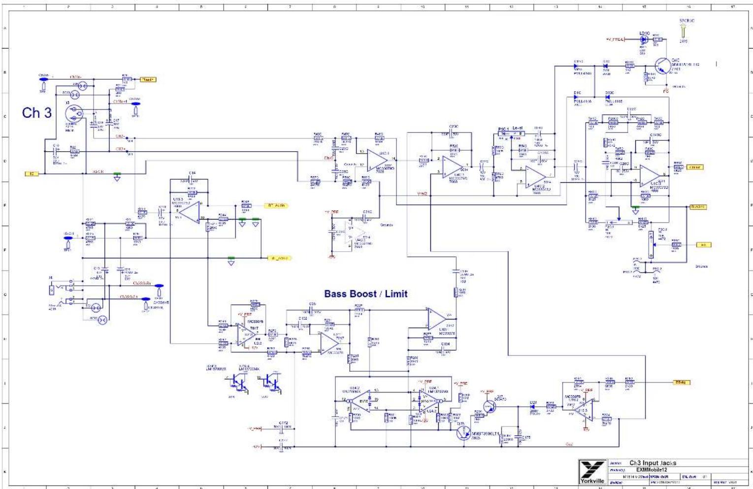
other
| Component | Frequency (Hz) | |-----------|----------------| | C11a-4 | 2.0 | | C12a | 2.0 | | C13a | 2.0 | | C14 | 2.0 | | C15 | 2.0 | | C16 | 2.0 | | C17 | 2.0 | | C18 | 2.0 | | C19 | 2.0 | | C20 | 2.0 | | C21 | 2.0 | | C22 | 2.0 | | C23 | 2.0 | | C24 | 2.0 | | C25 | 2.0 | | C26 | 2.0 | | C27 | 2.0 | | C28 | 2.0 | | C29 | 2.0 | | C30 | 2.0 | | C31 | 2.0 | | C32 | 2.0 | | C33 | 2.0 | | C34 | 2.0 | | C35 | 2.0 | | C36 | 2.0 | | C37 | 2.0 | | C38 | 2.0 | | C39 | 2.0 | | C40 | 2.0 | | C41 | 2.0 | | C42 | 2.0 | | C43 | 2.0 | | C44 | 2.0 | | C45 | 2.0 | | C46 | 2.0 | | C47 | 2.0 | | C48 | 2.0 | | C49 | 2.0 | | C50 | 2.0 | | C51 | 2.0 | | C52 | 2.0 | | C53 | 2.0 | | C54 | 2.0 | | C55 | 2.0 | | C56 | 2.0 | | C57 | 2.0 | | C58 | 2.0 | | C59 | 2.0 | | C60 | 2.0 | | C61 | 2.0 | | C62 | 2.0 | | C63 | 2.0 | | C64 | 2.0 | | C65 | 2.0 | | C66 | 2.0 | | C67 | 2.0 | | C68 | 2.0 | | C69 | 2.0 | | C70 | 2.0 | | C71 | 2.0 | | C72 | 2.0 | | C73 | 2.0 | | C74 | 2.0 | | C75 | 2.0 | | C76 | 2.0 | | C77 | 2.0 | | C78 | 2.0 | | C79 | 2.0 | | C80 | 2.0 | | C81 | 2.0 | | C82 | 2.0 | | C83 | 2.0 | | C84 | 2.0 | | C85 | 2.0 | | C86 | 2.0 | | C87 | 2.0 | | C88 | 2.0 | | C89 | 2.0 | | C90 | 2.0 | | C91 | 2.0 | | C92 | 2.0 | | C93 | 2.0 | | C94 | 2.0 | | C95 | 2.0 | | C96 | 2.0 | | C97 | 2.0 | | C98 | 2.0 | | C99 | 2.0 | | D1 | - | The chart displays the frequency (Hz) and amplitude (dB) of the output signal in the channel 'Ch 3'. The output signal is measured by the 'B' component in the output 'B'. The output signal is measured by the 'Cap' component in the output 'Cap'. The output signal is measured by the 'Cap' component in the output 'Cap'. The output signal is measured by the 'Cap' component in the output 'Cap'. The output signal is measured by the 'Cap' component in the output 'Cap'. The output signal is measured by the 'Cap' component in the output 'Cap'. The output signal is measured by the 'Cap' component in the output 'Cap'. The output signal is measured by the 'Cap' component in the outputs 'Cap' and 'Cap'. The output signal is measured by the 'Cap' component in the outputs 'Cap' and 'Cap'. The output signal is measured by the 'Cap' component in the outputs 'Cap' and 'Cap'. The output signal is measured by the 'Cap' component in the outputs 'Cap' and 'Cap'. The output signal is measured by the 'Cap' component in the outputs 'Cap' and 'Cap'. The output signal is measured by the 'Cap' component in both 'Cap' and 'Cap'. The output signal is measured by the 'Cap' component in the outputs 'Cap' and 'Cap'. The output signal is measured by the 'Cap' component in the outputs 'Cap' and 'Cap'. The output signal is measured by the 'Cap' component in the outputs 'Cap' and 'Cap'. The output signal is measured by the 'Cap' component in the outputs 'Cap' and 'Cap'. The output signal is measured by the 'OpA' component in the outputs 'OpA' and 'OpA', which is measured at -1V to +1V amplitude levels.


other
| Component | Pin Label | Power (V) | | :--- | :--- | :--- | | +27In | | | | R203 2K0 5N15 | | | | R220 2K0 5N05 | | | | R259 1K0 5N05 | | | | R260 2K0 5N05 | | | | R261 1K0 5N05 | | | | D38 5O123 4V7 | LD3:1 Charge | | | D38 5O123 4V7 | RED Charge | | | D43 1/2 0W5 RL7.5B | | | | R233 1K0 0N15 | Q14 2N7002 7986 SOT-23 | | | R242 100K0 0N15 | | | | R246 20K5 2N15 | LD9 RLD Critical 7033 Q20 2N7002 7986 | | | R249 1K0 2N15 | Q20 2N7002 7986 | | | R255 100K0 2N15 | | | | R256 100K0 4N15 | LD9 RLD Critical 7033 Q20 2N7002 7986 | | | R257 100K0 0N15 | LD9 RLD Critical 7033 Q20 2N7002 7986 | | | R265 562R0 0N15 | D39 D12 PMLL4148 SOT-60 | | | R265 562R0 0N15 | D27 PMLL4148 SOT-60 | | | Q15 MMBT3906LT1 7805 LD5 YEL 5U 7032 | LD9 RLD Critical 7033 Q20 2N7002 7986 | | | Q15 MMBT3906LT1 7805 LD5 YEL 5U 7032 | LD9 RLD Critical 7033 Q20 2N7002 7986 | | | Q15 MMBT3906LT1 7805 LD5 YEL 5U 7032 | LD9 RLD Critical 7086 Q21 2N7002 7986 | | | Q15 MMBT3906LT1 7805 LD5 YEL 5U 7032 | LD9 RLD Critical 7086 Q21 2N7002 7986 | | | Q15 MMBT3906LT1 7805 LD5 YEL 5U 731 | LD9 RLD Critical 7086 Q21 2N7002 7986 | | | Q15 MMBT3906LT1 7805 LD5 YEL 5U 731 | LD9 RLD Critical 7086 Q21 2N7002 7986 | | | Q15 MMBT3906LT1 8D8 | LD9 RLD Critical 7086 Q21 2N7002 7986 | | | Q15 MMBT3906LT1 8D8 | LD9 RLD Critical 7086 Q21 2N7002 7986 | | | Q15 MMBT3906LT1 8D8 | LD9 RLD Critical 70ALED Q21 2N7002 7986 | | | Q15 MMBT3906LT1 8D8 | LD9 RLD Critical 70ALED Q21 2N7002 7986 | | | Q15 MMBT3906LT1 8D8 | LD9 RLD Critical 70ALED Q21 2N7004 7986 | | | Q15 MMBT3906LT1 8D8 | LD9 RLD Critical 70ALED Q21 2N7004 7986 | | | Q15 MMBT3906LT1 8D8 | LD9 RLD Critical 70ALED Q21 2N7004 7986 | | | Q23 N7002 TSPCR4 SPCR5 SPCR6 SPCR6 SPCR6 SPCR6 SPCR6 SPCR6 SPCR6 SPCR6 SPCR6 SPCR6 SPCR6 SPCR6 SPCR6 SPCR6 SPCR6 SPCR6 SPCR6 SPCR6 SPCR6 SPCR6 SPCR6 SPCR6 SPCR6 SPCR6 SPCR6 SPCR4 SPCR4 SPCR4 SPCR4 SPCR4 SPCR4 SPCR4 SPCR4 SPCR4 SPCR4 SPCR4 SPCR4 SPCR4 SPCR4 SPCR4 SPCR4 SPCR4 SPCR4 SPCR4 SPCR4 SPCR4 SPCR4 SPCR4 SPCR4 SPCR4 SPCR3 SPCR3 SPCR3 SPCR3 SPCR3 SPCR3 SPCR3 SPCR3 SPCR3 SPCR3 SPCR3 SPCR3 SPCR3 SPCR3 SPCR3 SPCR3 SPCR3 SPCR3 SPCR3 SPCR3 SPCR3 SPCR3 SPCR3 SPCR3 SPCR3 SPCR4 SPCR4 SPCR4 SPCR4 SPCR4 SPCR4 SPCR4 SPCR4 SPCR4 SPCR4 SPCR4 SPCR4 SPCR4 SPCR4 SPCR4 SPCR4 SPCR4 SPCR4 SPCR4 SPCR4 SPCR4 SPCR4 SPCR4 SPCR4 SPCR5 SPCR5 SPCR5 SPCR5 SPCR5 SPCR5 SPCR5 SPCR5 SPCR5 SPCR5 SPCR5 SPCR5 SPCR5 SPCR5 SPCR5 SPCR5 SPCR5 SPCR5 SPCR5 SPCR5 SPCR5 SPCR5 SPCR5 SPCR5 G Legend - -12V - - | Section: Battery Status Product(s): EXMMobile12 M1814 B Sheet D/PCI#:Rev#: EML Rev#: OI Modified: 2019-09-17 File: BatteryStatusLEDs.SchDoc Tmp Rev: V031DESIGN HISTORY AND INFORMATION
CHANGE HISTORY
| # | DATE | VER# | PC# | DESCRIPTION OF CHANGE |
| 1 | 08 JAN 2019 | V01 | RELEASED FOR PRODUCTION | |
| 2 | 17-Sept-2019 | 9437 | Change R248 1K21 to 4K99, R244 1K21 to 4K90, R172 82K5 to 274K. | |
| 3 | ||||
| 4 | ||||
| 5 | ||||
| 6 | ||||
| 7 | ||||
| 8 | ||||
| 9 | ||||
| 10 | ||||
| 11 | ||||
| 12 | ||||
| 13 | ||||
| # | DATE | VER# | PC# | DESCRIPTION OF CHANGE |
| 1 | ||||
| 2 | ||||
| 3 | ||||
| 4 | ||||
| 5 | ||||
| 6 | ||||
| 7 | ||||
| 8 | ||||
| 9 | ||||
| 10 | ||||
| 11 | ||||
| 12 | ||||
| 13 | ||||
| # | DATE | VEER# | PC# | DESCRIPTION OF CHANGE |
| 1 | ||||
| 2 | ||||
| 3 | ||||
| 4 | ||||
| 5 | ||||
| 6 | ||||
| 7 | ||||
| 8 | ||||
| 9 | ||||
| 10 | ||||
| 11 |
POTENTIOMETERS AND KNOBS
| POTENTIOMETERS/SWITCHES AND KNOBS | ||||
| REF | FUNCTION | POT/SW YSM | STYLE | KNOB# |
| P1A | LEVEL | 4483 | P32 | 10043 |
| P1B | LEVEL | 4483 | P32 | 10043 |
| P1C | LEVEL | 4483 | P32 | 10043 |
| P2A | Shape | 4472 | P32 | 9921 |
| P2B | Shape | 4472 | P32 | 9921 |
| P2C | Shape | 4472 | P32 | 9921 |
| P3A | FX Send | 4472 | P32 | 9921 |
| P3B | FX Send | 4472 | P32 | 9921 |
| P3C | FX Send | 4472 | P32 | 9921 |
| P4 | Master | 4433 | P32 | 10043 |
| S1 | FX Select | 4189 | 10045 | |

STYLE_PNS
THIS SHEET CONTAINS A CHANGE HISTORY LOG, A LIST OF THE POTS & KNOBS AND A LEADS & PINS REFERENCE SECTION.
| Yorkville | Design Information And History | |||
| EXMMobile12 | ||||
| N 15 14 9 25 mm | P 20% mm | D % mm | 0 | |
| 25% m3 | P 6 - 150000000000000000000000000000000000000000000000000000000000000000000000000000000000000000000000000000 | 15 | 16 | |

PCB ASSEMBLY DOCUMENTATION
SPECIAL PRODUCTION NOTES
-
RTV ALL TALL CAPS
-
USE PIZZA CUTTER TO SEPARATE BOARD FROM PANEL.
Please make sure C3 is VERTICAL
and not bent over covering the LED
LD1A


Please make sure C21A, C21B, C24C are
not bent over covering the LEDs next to them
LD1A, LD1B, LD1C
THIS SHEET CONTAINS SPECIAL PRODUCTION NOTES AND A LIST OF PCB HARDWARE PARTS REQUIRED FOR THE BUILD.

Assembly Documentation
EXMMobile12
N124 10 115610708900A EML 00-01
| Yorkville | Design Information And History | |||
| EXMMobile12 | ||||
| N15 14 0 25nd | P9788 1st | D6 1nd | 01 | |
| 2nd | P# 1nd | P# 2nd | 1st | |


flowchart
graph TD
    subgraph Power_Side
        direction TB
        A["Micro"] --> B["LEDs_EN"]
        A --> C["RED_LED"]
        A --> D["100L_D"]
        A --> E["75LED"]
        A --> F["Charging_LED"]
        A --> G["ChargeLED"]
        H["LinkMate"] --> I["AMMIDUE Enable"]
        J["ToMgnd"] --> K["BUCK_EN"]
        L["BUCK_EN"] --> M["PREFAMP ENABLE"]
        N["PREFAMP ENABLE"] --> O["PREFAMP ENABLE"]
        P["PREFAMP ENABLE"] --> Q["PREFAMP ENABLE"]
        R["PREFAMP ENABLE"] --> S["PREFAMP ENABLE"]
        T["PREFAMP ENABLE"] --> U["PREFAMP ENABLE"]
        V["PREFAMP ENABLE"] --> W["PREFAMP ENABLE"]
        X["PREFAMP ENABLE"] --> Y["PREFAMP ENABLE"]
        Z["PREFAMP ENABLE"] --> AA["PREFAMP ENABLE"]
        AB["PREFAMP ENABLE"] --> AC["PREFAMP ENABLE"]
        AD["PREFAMP ENABLE"] --> AE["PREFAMP ENABLE"]
        AF["PREFAMP ENABLE"] --> AG["PREFAMP ENABLE"]
        AH["PREFAMP ENABLE"] --> AI["PREFAMP ENABLE"]
        AJ["PREFAMP ENABLE"] --> AK["PREFAMP ENABLE"]
        AL["PREFAMP ENABLE"] --> AM["PREFAMP ENABLE"]
        AN["PREFAMP ENABLE"] --> AO["PREFAMP ENABLE"]
        AP["PREFAMP ENABLE"] --> AQ["PREFAMP ENABLE"]
        AR["PREFAMP ENABLE"] --> AS["PREFAMP ENABLE"]
        AT["PREFAMP ENABLE"] --> AU["PREFAMP ENABLE"]
        AV["PREFAMP ENABLE"] --> AW["PREFAMP ENABLE"]
        AX["PREFAMP ENABLE"] --> AY["PREFAMP ENABLE"]
        AZ["PREFAMP ENABLE"] --> BA["PREFAMP ENABLE"]
        BB["PREFAMP ENABLE"] --> BC["PREFAMP ENABLE"]
        BD["PREFAMP ENABLE"] --> BE["PREFAMP ENABLE"]
        BF["PREFAMP ENABLE"] --> BG["PREFAMP ENABLE"]
        BH["PREFAMP ENABLE"] --> BI["PREFAMP ENABLE"]
        BJ["PREFAMP ENABLE"] --> BK["PREFAMP ENABLE"]
        BL["PREFAMP ENABLE"] --> BLP["PREFAMP ENABLE"]
        BM["PREFAMP ENABLE"] --> BN["PREFAMP ENABLE"]
        BO["PREFAMP ENABLE"] --> BP["PREFAMP ENABLE"]
        BP["PREFAMP ENABLE"] --> BQ["PREFAMP ENABLE"]
        BR["PREFAMP ENABLE"] --> BS["PREFAMP ENABLE"]
        BT["PREFAMP ENABLE"] --> BU["PREFAMP ENABLE"]
        BV["PREFAMP ENABLE"] --> BW["PREFAMP ENABLE"]
        BX["PREFAMP ENABLE"] --> BY["PREFAMP ENABLE"]
        CA["PREFAMP ENABLE"] --> CB["PREFAMP ENABLE"]
        CC["PREFAMP ENABLE"] --> CD["PREFAMP ENABLE"]
        DD["PREFAMP ENABLE"] --> DE["PREFAMP ENABLE"]
        FD["PREFAMP ENABLE"] --> FDp["PREFAMP ENABLE"]
        FDq["PREFAMP ENABLE"] --> FDqP["PREFAMP ENABLE"]
        FDpP["PREFAMP ENABLE"] --> FDpP["PREFAMP ENABLE"]
        FDqP["PREFAMP ENABLE"] --> FDqP["PREFAMP ENABLE"]
        FDqP["PREFAMP ENABLE"] --> FDqP["PREFAMP ENABLE"]
        DG["Power Supply & Battery/Ctrl.SchDoc"] --> DH["PowerSupply & Battery/Ctrl.SchDoc"]
    end

    subgraph Legend
        E["Power Supply & Battery/Ctrl.SchDoc"] --> E
    end

    %% Legend
    E["Power Supply & Battery/Ctrl.SchDoc"] --> E
    %% Legend
    E["Power Supply & Battery/Ctrl.SchDoc"] --> E
    %% Legend
    E["Power Supply & Battery/Ctrl.SchDoc"] --> E
    %% Legend
    E["Power Supply & Battery/Ctrl.SchDoc"] --> E
    %% Legend
    E["Power Supply & Battery/Ctrl.SchDoc"] --> E
    %% Legend
    E["Power Supply & Battery/Ctrl.SchDoc"] --> E

| M1815 2 7 Sheet | OPC#B: R#B#: | ENL Rev#: 01 | |
| Modified | File:2PNav6S&SupplySection.SchDoc | Temp Rev: V031 | |


| 10-Pin Cortex Debug Connector | 6-Pin TC2030 Footprint | |
| 1 VCC | 2 SWDIO / TMS | 1 VCC |
| 3 GND | 4 SWCLK / TCK | 2 SWDIO / TMS |
| 5 GND | 6 SWO / TDO | 3 nRESET |
| 7 NC / RTCK | 8 NC / TDI | 4 SWCLK / TCK |
| 9 GNDDetect | 10 nRESET | 5 GND (also connected to GNDDetect) |
| 6 SWO / TDO | ||

| Yorkville Section: Microcontroller | |||||
| Product(s): EXMMobile 12 | |||||
| M1815.47 Modified: | V01 | EML Rev#: 01 | Sheet OIPCBF: Rev#: | ||
| File: 2018-0626.Dcc | Temp Rev: V031 | ||||
| 12 | 13 | 14 | 15 | 16 | 17 |

| Yorkville | Section: Power Amp | |||
| Product#: EXMMobile 12 | ||||
| PCM: M1015 | Rev: V01 | EKL Rev: 01 | Sheet 0 Of 7 | |
| Mod/Doc: 2019-09-20 | FIC: Power Amp.SchDoc | Top Rev: V031 | ||

DESIGN HISTORY AND INFORMATION
CHANGE HISTORY
| # | DATE | VER# | PC# | DESCRIPTION OF CHANGE |
| 1 | 05 JAN 2019 | V01 | RELEASED FOR PRODUCTION | |
| 2 | ||||
| 3 | ||||
| 4 | ||||
| 5 | ||||
| 6 | ||||
| 7 | ||||
| 8 | ||||
| 9 | ||||
| 10 | ||||
| 11 | ||||
| 12 | ||||
| 13 | ||||
| # | DATE | VER# | PC# | DESCRIPTION OF CHANGE |
| 1 | ||||
| 2 | ||||
| 3 | ||||
| 4 | ||||
| 5 | ||||
| 6 | ||||
| 7 | ||||
| 8 | ||||
| 9 | ||||
| 10 | ||||
| 11 | ||||
| 12 | ||||
| 13 | ||||
| # | DATE | VER# | PC# | DESCRIPTION OF CHANGE |
| 1 | ||||
| 2 | ||||
| 3 | ||||
| 4 | ||||
| 5 | ||||
| 6 | ||||
| 7 | ||||
| 8 | ||||
| 9 | ||||
| 10 |
THIS SHEET CONTAINS A CHANGE HISTORY LOG, A LIST OF THE POTS & KNOBS AND A LEADS & PINS REFERENCE SECTION.

| Design Information And History | |||
| EXMMobile 12 | |||
| N 12 13 6/75wd | P 000000000 | E 400000000 | |
| P 000000000 | P 000000000 | E 400000000 | E 400000000 |
SPECIAL PRODUCTION NOTES
PCB ASSEMBLY DOCUMENTATION
EXM-70/EXMMobile/12 Heatsink Jig.

natural_image
Close-up of a metallic electronic component with a small yellow component, placed on a dark surface (no visible text or symbols)1) Place the EXMMobile 12guide on the jig.

2) Place the 6698 heatsink in the guide.

Heatsin Assembly PCB Finis ing
3) Flip the guide for the 4236 pad onto the heatsink.

natural_image
Close-up of a metallic electronic component with mounting holes and a red 'EXH-MODILE' label (no other text or symbols visible)4) Place the 4236 pad onto the heatsink.

5) Flip the pad guide out of the way.

6) Place board face down on the jig. Pin at the two lower corners.

natural_image
Green printed circuit board with red arrows pointing to specific components (no readable text or symbols)7) Mount 6698 using 2 8807 screws.
Dip the screws in Loctite.
Tighten to 4 in/lbs.

natural_image
Close-up of hands performing a dental procedure on a small tooth model (no text or symbols visible)

RTV in hole underneath L5.

natural_image
Close-up of a green printed circuit board with visible traces and components (no readable text or symbols)
THIS SHEET CONTAINS SPECIAL PRODUCTION NOTES AND A LIST OF PCB HARDWARE PARTS REQUIRED FOR THE BUILD.

Assembly Documentation
EXMMobile 12
N1815 (7/5)wd 09/06-04/08 EML (2014) 0
2016年

24.1 10V356 0273

See PcbDoc for default clearance rules.
Note: You must define your own rules for -HI and +HI.

ECAD Incidents
EXMMobile 12
N12129756nd 0708-088 EMLand
2017年
(1) 本说明仅供参考。

SPECIAL PRODUCTION NOTES
PCB ASSEMBLY DOCUMENTATION
Heatsin Assembly PCB Finis ing
EXM-70/EXMMobile/12 Heatsink Jig.

natural_image
Close-up of a small electronic component with a yellow body and metallic contacts, placed on a flat surface against a dark textured background (no visible text or symbols)3) Flip the guide for the 4236 pad onto the heatsink.

natural_image
Close-up of an electronic component with metallic casing and mounting holes, labeled 'EXH-MOBILE' (no other text or symbols visible)6) Place board face down on the jig. Pin at the two lower corners.

natural_image
Green printed circuit board with visible traces and components, no readable text or symbols
1) Place the EXMMobile 12guide on the jig.

4) Place the 4236 pad onto the heatsink.
Handle the 4236 pad by the edges only.

natural_image
Close-up of a hand holding a small metal component, with no visible text or symbols on the component itself.7) Mount 6698 using 2 8807 screws.
Dip the screws in Loctite.
Tighten to 4 in/lbs.

natural_image
Close-up of hands performing a procedure on a small object, possibly a dental or mechanical component (no visible text or symbols)RTV in hole underneath L5.

natural_image
Close-up of a green printed circuit board with visible traces and components (no readable text or symbols)2) Place the 6698 heatsink in the guide.

5) Flip the pad guide out of the way.


Dip each screw in Loctite. Cover 2 threads.

THIS SHEET CONTAINS SPECIAL PRODUCTION NOTES AND A LIST OF PCB HARDWARE PARTS REQUIRED FOR THE BUILD.
| Yorkville Assembly Documentation | ||||
| Products EXMMobile12 | ||||
| P258. V104 | Vcc. V01 | EML.Avr. 01 | Gmcl. Gk | |
| P259. 2014-02-06 | File Assembly Set Doc | Top S### V034 | ||
DESIGN HISTORY AND INFORMATION
CHANGE HISTORY
| # | DATE | VER# | PC# | DESCRIPTION OF CHANGE |
| 1 | 06-JAN-2019 | V01 | RELEASED FOR PRODUCTION | |
| 2 | ||||
| 3 | ||||
| 4 | ||||
| 5 | ||||
| 6 | ||||
| 7 | ||||
| 8 | ||||
| 9 | ||||
| 10 | ||||
| 11 | ||||
| 12 | ||||
| 13 | ||||
| # | DATE | VER# | PC# | DESCRIPTION OF CHANGE |
| 1 | ||||
| 2 | ||||
| 3 | ||||
| 4 | ||||
| 5 | ||||
| 6 | ||||
| 7 | ||||
| 8 | ||||
| 9 | ||||
| 10 | ||||
| 11 | ||||
| 12 | ||||
| 13 | ||||
| # | DATE | VER# | PC# | DESCRIPTION OF CHANGE |
| 1 | ||||
| 2 | ||||
| 3 | ||||
| 4 | ||||
| 5 | ||||
| 6 | ||||
| 7 | ||||
| 8 | ||||
| 9 | ||||
| 10 |
THIS SHEET CONTAINS A CHANGE HISTORY LOG, A LIST OF THE POTS & KNOBS AND A LEADS & PINS REFERENCE SECTION.
| Yorkville | Design Information And History | |||||
| Products EXMMobile12 | ||||||
| P250. | P350.7 | P45. V01 | EMLAvei | D1 | Gnd. 6Y | |
| P450. | 20-4-02-06 | Fk. History Set Doc | Pca Ave. V004 | |||


DESIGN HISTORY AND INFORMATION
CHANGE HISTORY
| # | DATE | VER# | PC# | DESCRIPTION OF CHANGE |
| 1 | 08-JAN-2019 | V01 | RELEASED FOR PRODUCTION | |
| 2 | ||||
| 3 | ||||
| 4 | ||||
| 5 | ||||
| 6 | ||||
| 7 | ||||
| 8 | ||||
| 9 | ||||
| 10 | ||||
| 11 | ||||
| 12 | ||||
| 13 | ||||
| # | DATE | VER# | PC# | DESCRIPTION OF CHANGE |
| 1 | ||||
| 2 | ||||
| 3 | ||||
| 4 | ||||
| 5 | ||||
| 6 | ||||
| 7 | ||||
| 8 | ||||
| 9 | ||||
| 10 | ||||
| 11 | ||||
| 12 | ||||
| 13 | ||||
| # | DATE | VER# | PC# | DESCRIPTION OF CHANGE |
| 1 | ||||
| 2 | ||||
| 3 | ||||
| 4 | ||||
| 5 | ||||
| 6 | ||||
| 7 | ||||
| 8 | ||||
| 9 | ||||
| 10 |
THIS SHEET CONTAINS A CHANGE HISTORY LOG, A LIST OF THE POTS & KNOBS AND A LEADS & PINS REFERENCE SECTION.
| Yorkville | Design Information And History | |||
| ExMMobile 12 | ||||
| PDB | MDDH | AVG | AVG | |
| PHS | A | TNB | TNB | |

PCB ASSEMBLY DOCUMENTATION
SPECIAL PRODUCTION NOTES
Put Data Matrix Label #8372 on top of U17.

THIS SHEET CONTAINS SPECIAL PRODUCTION NOTES AND A LIST OF PCB HARDWARE PARTS REQUIRED FOR THE BUILD.
DESIGN HISTORY AND INFORMATION
CHANGE HISTORY
| # | DATE | VER# | PC# | DESCRIPTION OF CHANGE |
| 1 | 08-JAN-2019 | V01 | RELEASED FOR PRODUCTION | |
| 2 | ||||
| 3 | ||||
| 4 | ||||
| 5 | ||||
| 6 | ||||
| 7 | ||||
| 8 | ||||
| 9 | ||||
| 10 | ||||
| 11 | ||||
| 12 | ||||
| 13 | ||||
| # | DATE | VER# | PC# | DESCRIPTION OF CHANGE |
| 1 | ||||
| 2 | ||||
| 3 | ||||
| 4 | ||||
| 5 | ||||
| 6 | ||||
| 7 | ||||
| 8 | ||||
| 9 | ||||
| 10 | ||||
| 11 | ||||
| 12 | ||||
| 13 | ||||
| # | DATE | VER# | PC# | DESCRIPTION OF CHANGE |
| 1 | ||||
| 2 | ||||
| 3 | ||||
| 4 | ||||
| 5 | ||||
| 6 | ||||
| 7 | ||||
| 8 | ||||
| 9 | ||||
| 10 |
THIS SHEET CONTAINS A CHANGE HISTORY LOG, A LIST OF THE POTS & KNOBS AND A LEADS & PINS REFERENCE SECTION.


| Yorkville Sound Ltd |
| 650 Granite CourtPickering, ONCanada (1W 3Y8www.yorkville.com) |
| Product(s): EXMmobile12 | |||
| Description: Battery Powered PA Speaker | |||
| M1914 1 10 | V05 | EVL Rev: 01 | Sheet OPCEst. Rev: |
| MaxWest: 2022-04-08 | Riv: Top Sheet SchDoc | Trip Rev: V031 | |


| Product#: EXMmobile12 | |||||
| Description: Battery Powered PA Speaker | |||||
| M1014 18 10 | V05 | EVL Rev: 01 | Shot OP/25r. Rev: | ||
| Model#: 2022-04-08 | Rc: BluetoothEM26.3chDoc | Tap Rev: VC81 | |||
| 12 | 13 | 14 | 15 | 16 | 17 |
DESIGN HISTORY AND INFORMATION
CHANGE HISTORY POTENTIOMETERS AND KNOBS
| # | DATE | VER# | PC# | DESCRIPTION OF CHANGE |
| 1 | 06.AUG-2020 | V01 | RELEASED FOR PRODUCTION | |
| 2 | 18-SEP-2020 | V02 | 9504 | Multiple revisions per schematics in PC9504 pd1 document |
| 3 | 18-NOV-2020 | V03 | 9507 | Replaced 6V regulators Q18 and Q19 i7918 with i8206 |
| 4 | 19-NOV-2020 | V03 | 9614 | Backed off +5V copper fill and trace from nitg screw in bluetooth section. |
| 5 | 12-JAN-2021 | V04 | 9619 | Retouted battery status and S3 connections according to PC9619. |
| 6 | 13-Sept-2021 | V04 | 9689 | Updated heatsink to in-house version, updated heatsink assembly instructions. |
| 7 | 07-APR-2022 | V05 | 9713 | Moved C170B away from mounting hole |
| 8 | ||||
| 9 | ||||
| 10 | ||||
| 11 | ||||
| 12 | ||||
| 13 | ||||
| # | DATE | VER# | PC# | DESCRIPTION OF CHANGE |
| 1 | ||||
| 2 | ||||
| 3 | ||||
| 4 | ||||
| 5 | ||||
| 6 | ||||
| 7 | ||||
| 8 | ||||
| 9 | ||||
| 10 | ||||
| 11 | ||||
| 12 | ||||
| 13 |
| POTENTIOMETERS/SWITCHES AND kNOBS | ||||
| REF | FUNCTION | POT.SW YS# | STYLE | kNOB# |
| P1A | LEVEL | 4486 | P32 | |
| P1B | LEVEL | 4486 | P32 | |
| P1C | LEVEL | 4486 | P32 | |
| P2A | Shape | 4472 | P32 | |
| P2B | Shape | 4472 | P32 | |
| P2C | Shape | 4472 | P32 | |
| P3A | FX Send | 4471 | P32 | |
| P3B | FX Send | 4471 | P32 | |
| P3C | FX Send | 4471 | P32 | |
| P4 | Master | 4433 | P32 | |
| S1 | FX Select | 4189 | ||
| S2 | BT Pair | 3499 | ||
| S3 | Power | 3522 | ||

THIS SHEET CONTAINS A CHANGE HISTORY LOG. A LIST OF THE POTS & KNOBS AND A LEADS & PINS REFERENCE SECTION.


M1914- EXMmobile12

M1914- EXMmobile12

other
The image displays a schematic diagram of a power system. It includes multiple labeled components (e.g., 'Power', 'Charge', 'Master') arranged in a grid layout with red annotations indicating specific nodes or connections. The diagram includes labels such as 'Power', 'Charge', 'Master', and 'Input'. Numbers (e.g., 100N, 20K, 3439) are positioned around the diagram. Some components are marked with red arrows, possibly indicating signal or control points. The diagram is integrated into a grid layout with alphanumeric labels (e.g., 'Power', 'Charge', 'Master') and contains no explicit numerical values but likely representing a technical or operational schematic.

ATTENTION
ELECTROSTATIC
SENSITIVE DEVICE


100N
C173
BM20
U17
Blue Tooth M1942 V05
R215
100K0
TCM809
Q17
PCB ASSEMBLY DOCUMENTATION
SPECIAL PRODUCTION NOTES
1) Place both YS#8741 screws through the heatink and secure with two YS#8793 nuts. Tighten to 4 in. lbs.

natural_image
Metal plate with two black toggle switches (no text or symbols visible)2) Add YS#4236 gappad to U8. Handle the gappad edges only, ensure the pad is centered over U8.

natural_image
Close-up of a green printed circuit board with visible traces and components (no readable text or symbols)Heatsin Assembly PCB Finis ing
3) Place heatsink assembly from step 1 through the PCB and on top of the gappad. Hold in place from the centre with the clip.

natural_image
Close-up of a computer motherboard with electronic components and a black plastic clip (no visible text or symbols)4) Flip over the PCB and apply Permabond MM115 Threadlocker to each screw. Secure heatsink to PCB with two YS#8701 nuts. Tighten to 4 In. lbs.

natural_image
Close-up of a green printed circuit board with black plastic bands and screw holes (no readable text or symbols)The input section needs to be Bir tight. All viBs Bnd pBrt holes must be filled with solder.
Apply Permabond to the end of each screw.
PCB HARDWARE


THIS SHEET CONTAINS SPECIAL PRODUCTION NOTES AND A LIST OF PCB HARDWARE PARTS REQUIRED FOR THE BUILD.

Secture Assembly Documentation
M1914 LWS P.Harson
M1914 705 KPH302 Exdc 705281000000chDoc
DESIGN HISTORY AND INFORMATION
CHANGE HISTORY POTENTIOMETERS AND KNOBS
| # | DATE | VER# | PC# | DESCRIPTION OF CHANGE |
| 1 | 06.AUG-2020 | V01 | RELEASED FOR PRODUCTION | |
| 2 | 18-SEP-2020 | V02 | 9504 | Multiple revisions per schematics in PC9504 pd1 document |
| 3 | 18-NOV-2020 | V03 | 9507 | Replaced 6V regulators Q18 and Q19 i7918 with i8206 |
| 4 | 19-NOV-2020 | V03 | 9614 | Backed off +5V copper fill and trace from nitg screw in bluetooth section. |
| 5 | 12-JAN-2021 | V04 | 9619 | Retouted battery status and S3 connections according to PC9619. |
| 6 | 13-Sept-2021 | V04 | 9689 | Updated heatsink to in-house version, updated heatsink assembly instructions. |
| 7 | 07-APR-2022 | V05 | 9713 | Moved C170B away from mounting hole |
| 8 | ||||
| 9 | ||||
| 10 | ||||
| 11 | ||||
| 12 | ||||
| 13 | ||||
| # | DATE | VER# | PC# | DESCRIPTION OF CHANGE |
| 1 | ||||
| 2 | ||||
| 3 | ||||
| 4 | ||||
| 5 | ||||
| 6 | ||||
| 7 | ||||
| 8 | ||||
| 9 | ||||
| 10 | ||||
| 11 | ||||
| 12 | ||||
| 13 |
| POTENTIOMETERS/SWITCHES AND kNOBS | ||||
| REF | FUNCTION | POT.SW YS# | STYLE | kNOB# |
| P1A | LEVEL | 4486 | P32 | |
| P1B | LEVEL | 4486 | P32 | |
| P1C | LEVEL | 4486 | P32 | |
| P2A | Shape | 4472 | P32 | |
| P2B | Shape | 4472 | P32 | |
| P2C | Shape | 4472 | P32 | |
| P3A | FX Send | 4471 | P32 | |
| P3B | FX Send | 4471 | P32 | |
| P3C | FX Send | 4471 | P32 | |
| P4 | Master | 4433 | P32 | |
| S1 | FX Select | 4189 | ||
| S2 | BT Pair | 3499 | ||
| S3 | Power | 3522 | ||

THIS SHEET CONTAINS A CHANGE HISTORY LOG. A LIST OF THE POTS & KNOBS AND A LEADS & PINS REFERENCE SECTION.


flowchart
graph TD
    A["Input"] --> B["BlueTooth"]
    B --> C["EXMmobile and EXM70 #3092 Cable"]
    B --> D["EXMmobile12 #3115 Cable"]
    B --> E["#3124 Cable"]
    E --> F["PowerSupply"]
    F --> G["-V_In"]
    F --> H["-V_In"]
    F --> I["-V_1"]
    F --> J["-V_2"]
    F --> K["-V_3"]
    F --> L["-V_4"]
    F --> M["-V_5"]
    F --> N["-V_6"]
    F --> O["-V_7"]
    F --> P["-V_8"]
    F --> Q["-V_9"]
    F --> R["-V_10"]
    F --> S["-V_11"]
    F --> T["-V_12"]
    F --> U["-V_13"]
    F --> V["-V_14"]
    F --> W["W3"]
    W --> X["W3_1"]
    W --> Y["W3_2"]
    W --> Z["W3_3"]
    W --> AA["W3_4"]
    W --> AB["W3_5"]
    W --> AC["W3_6"]
    W --> AD["W3_7"]
    W --> AE["W3_8"]
    W --> AF["W3_9"]
    W --> AG["W3_10"]
    W --> AH["W3_11"]
    W --> AI["W3_12"]
    W --> AJ["S2"]
    AJ --> AK["S2"]
    AK --> AL["S1"]
    AL --> AM["S2"]
    AM --> AN["S1"]
    AN --> AO["S2"]
    AO --> AP["S1"]
    AP --> AQ["S2"]
    AQ --> AR["S1"]
    AR --> AS["S2"]
    AS --> AT["S1"]
    AT --> AU["S2"]
    AU --> AV["S1"]
    AV --> AW["S2"]
    AW --> AX["S1"]
    AX --> AY["S2"]
    AY --> AZ["S1"]
    AZ --> BA["S2"]
    BA --> BB["S1"]
    BB --> BC["S2"]
    BC --> BD["S1"]
    BD --> BE["S2"]
    BE --> BF["S1"]
    BF --> BG["S2"]
    BG --> BH["S1"]
    BH --> BI["S2"]
    BI --> BJ["S1"]
    BJ --> BK["S2"]
| Yorkville | Section: Top Level | |||
| Product(s): EXMmobile12 | ||||
| PCB#: M2219 | Rev#: V01 | Eng.R. Himbsault | Sheet 1 Of 4 | |
| Modified: | File: 2002p EB68t.SchDoc | |||


DESIGN HISTORY AND INFORMATION
CHANGE HISTORY
| # | DATE | VER# | PC# | DESCRIPTION OF CHANGE |
| 1 | 01-DEC-2023 | V01 | Release for Production | |
| 2 | ||||
| 3 | ||||
| 4 | ||||
| 5 | ||||
| 6 | ||||
| 7 | ||||
| 8 | ||||
| 9 | ||||
| 10 | ||||
| 11 | ||||
| 12 | ||||
| 13 | ||||
| # | DATE | VER# | PC# | DESCRIPTION OF CHANGE |
| 1 | ||||
| 2 | ||||
| 3 | ||||
| 4 | ||||
| 5 | ||||
| 6 | ||||
| 7 | ||||
| 8 | ||||
| 9 | ||||
| 10 | ||||
| 11 | ||||
| 12 | ||||
| 13 | ||||
| # | DATE | VER# | PC# | DESCRIPTION OF CHANGE |
| 1 | ||||
| 2 | ||||
| 3 | ||||
| 4 | ||||
| 5 | ||||
| 6 | ||||
| 7 | ||||
| 8 | ||||
| 9 | ||||
| 10 |
THIS SHEET CONTAINS A CHANGE HISTORY LOG, A LIST OF THE POTS & KNOBS AND A LEADS & PINS REFERENCE SECTION.


other
| Component | Label | |---|---| | Power Supply | 2371 | | Battery | 4227 | | SPKR | 3538 | | 10UH | 10UH | | 10UH | 10UH | | 10UH | 10UH | | 10UH | 10UH | | 10UH | 10UH | | 10UH | 10UH | | 10UH | 10UH | | 10UH | 10UH | | 10UH | R243 | | 10UH | 39R | | 10UH | 47P | | 10UH | 47P | | 10UH | 47P | | 10UH | 47P | | 10UH | 47P | | 10UH | 47P | | 10UH | 47P | | 10UH | 47P | | 10UH | 47P | | 4227 | W11 | | 2371 | Power Supply | | 680N | 680N | | 680U | 680U | | C62 | C62 | | D20 | D20 | | F1 | F1 | | Q34 | Q34 | | B340 | B340 | | B340 | B340 | | B340 | B340 | | B340 | B340 | | B340 | B340 | | B340 | B340 | | B340 | B340 | | B340 | B340 | | B340 | B340 | | B340 | B340 | | | | | | | | | | | | | | | | | | | | | | | | | | | | | | | | | | | | | | | | | | | | | | | | | | | Power Supply M2219 ORO S/N LABEL Amp V01 M2241 Yorkville C127 D19 C53 D18 T5V5 C62 680N 680U 6V3 C62 D20 R229 R126 R240 R237 T5V5 C94 D18 C95 C94 D25 C188 C188 C188 C188 C188 C188 C188 C188 C188 C188 C188 C188 C188 C188 C188 C188 C188 C188 C188 C188 C186 C27 R245 R245 R245 R245 R245 R245 R245 R245 R245 R245 R245 R245 R245 R245 R245 R245 R245 R245 R245 R245 R24M2219-EXMmobile12
V01
SPECIAL PRODUCTION NOTES
- Follow instructions below to attach heatsink 7.1891 to board.
- Add RTV to the underside of L5 where indicated.
- Inspect bottom of board to ensure vias are filled with solder.
- Separate panel with pizza cutter and/or appropriate break out tool.
PCB ASSEMBLY DOCUMENTATION

IMPORTANT!
BEFORE WAVE SOLDER
1_ADD Soldermask dots to the two threaded spacers to bottom side of pcb.

AFTER WAVE SOLDER
1_Remove the Kapton tape both sides of the board from the spacers.

natural_image
Close-up of a green printed circuit board with two red arrows pointing to circular components (no visible text or symbols)Heatsin Assembly PCB Finis ing
- Remove YS44236 gappad from sheet and apply sticky side down to the top of U8. Handle the gappad edges only, ensure the pad is centered over U8.

natural_image
Close-up of a green printed circuit board with various electronic components and a red arrow pointing to a specific component (no visible text or symbols)3_Place HS1 (YS# Z1891) Heatsink directly on top of U8. Use legend outline as a guide.

natural_image
Diagram showing three labeled components on a circuit board with red arrows pointing to them (no text or symbols present)4_Secure heatsink HS1 with two 9441 screws. Tighten to 8 Inch lbs and make sure heatsink is sitting flat to spacers.

DESIGN HISTORY AND INFORMATION
CHANGE HISTORY
| # | DATE | VER# | PC# | DESCRIPTION OF CHANGE |
| 1 | 01-DEC-2023 | V01 | Release for Production | |
| 2 | ||||
| 3 | ||||
| 4 | ||||
| 5 | ||||
| 6 | ||||
| 7 | ||||
| 8 | ||||
| 9 | ||||
| 10 | ||||
| 11 | ||||
| 12 | ||||
| 13 | ||||
| # | DATE | VER# | PC# | DESCRIPTION OF CHANGE |
| 1 | ||||
| 2 | ||||
| 3 | ||||
| 4 | ||||
| 5 | ||||
| 6 | ||||
| 7 | ||||
| 8 | ||||
| 9 | ||||
| 10 | ||||
| 11 | ||||
| 12 | ||||
| 13 | ||||
| # | DATE | VER# | PC# | DESCRIPTION OF CHANGE |
| 1 | ||||
| 2 | ||||
| 3 | ||||
| 4 | ||||
| 5 | ||||
| 6 | ||||
| 7 | ||||
| 8 | ||||
| 9 | ||||
| 10 |
THIS SHEET CONTAINS A CHANGE HISTORY LOG, A LIST OF THE POTS & KNOBS AND A LEADS & PINS REFERENCE SECTION.

flowchart
graph TD
    subgraph BlueTooth
        A["EXMmobile and EXM70 #3092 Cable"] -->|W6 1 BT Status 7 BT SysPwr 7 BT Enable 7 BT +v 5 RT DGnd 6 BT AGnd 7 BT Audio| B["Input"]
        B --> C["+5VFX -12V Gnd_ +12V AmpGnd Ampln"]
        B --> D["Wake+ WAKE-"]
        E["BlueTooth"] --> F["Input Standalone"]
        F --> G["S2"]
        H["AMP"] --> I["#3124 Cable"]
        I --> J["#5099 Battery"]
    end

    subgraph PowerSupply
        K["#3094 Cable"] --> L["#3096 Cable"]
        L --> M["Input -85 -240 VAC"]
    end

    subgraph Power Supply
        N["#9709 Power Supply"]
        O["#5099 Battery"]
    end

    style BlueTooth fill:#f9f,stroke:#333
    style PowerSupply fill:#bbf,stroke:#333
    style Power Supply fill:#dfd,stroke:#333
    style Power Supply fill:#dfd,stroke:#333
    style Power Supply fill:#dfd,stroke:#333
    style Power Supply fill:#dfd,stroke:#333
    style Power Supply fill:#dfd,stroke:#333
    style Power Supply fill:#dfd,stroke:#333
    style Power Supply fill:#dfd,stroke:#333
    style Power Supply fill:#dfd, stroke:#333
    style Power Supply fill:#dfd, stroke:#333
    style Power Supply fill:#dfd, stroke:#333
    style Power Supply fill:#dfd, stroke:#333
    style Power Supply fill:#dfd, stroke:#333
    style Power Supply fill:#dfd, stroke:#333
    style Power Supply fill:#dfd, stroke:#333
    style Power Supply fill:#dfd, stroke:#�33
    style Power Supply fill:#dfd, stroke:#333
    style Power Supply fill:#dfd, stroke:#333
    style Power Supply fill:#dfd, stroke:#333
    style Power Supply fill:#dfd, stroke:#333
    style Power Supply fill:#dfd, stroke:#333
    style Power Supply fill:#dfd, stroke:#333
    style Power Supply fill:#dfd, stroke:#334

| Section: Top Level | |||
| Product(s): EXMmobile/EXMmobile12 | |||
| PCB#: M2240 | Rev#: V01 | Eng: GA, RR, RH | Sheet 1 Of 5 |
| Modified: | File:2023p E264t.SchDoc | ||


Effects selection
\$1 Pos Code Effect
| 1 | 0010 | Room3b-Reverb, Room (1.8 sec.) |
| 2 | 0110 | Room2a-Reverb Chapel (3 sec.) |
| 3 | 1010 Delay7-Echo | |
| 4 | N/A Off |

Yorkville
Digital Effects
Product(s): EXMmobile:EXMmobile12
PCBI: M2240 RevII: V01 Eng: GA, RR, RH Sheet 4 OF 5
File:2028-9@05c
DESIGN HISTORY AND INFORMATION
CHANGE HISTORY
| # | DATE | VER# | PC# | DESCRIPTION OF CHANGE |
| 1 | 0'-DEC-2023 | V01 | Release for Production | |
| 2 | ||||
| 3 | ||||
| 4 | ||||
| 5 | ||||
| 6 | ||||
| 7 | ||||
| 8 | ||||
| 9 | ||||
| 10 | ||||
| 11 | ||||
| 12 | ||||
| 13 | ||||
| # | DATE | VER# | PC# | DESCRIPTION OF CHANGE |
| 1 | ||||
| 2 | ||||
| 3 | ||||
| 4 | ||||
| 5 | ||||
| 6 | ||||
| 7 | ||||
| 8 | ||||
| 9 | ||||
| 10 | ||||
| 11 | ||||
| 12 | ||||
| 13 |
POTENTIOMETERS AND KNOBS
| POTENTIOMETERS: SWITCHES AND KNOBS | ||||
| REF | FUNCTION | POT/SW YS# | STYLE | KNOB# |
| P1A | LEVEL | 4486 | P32 | |
| P1B | LEVEL | 4486 | P32 | |
| P1C | LEVEL | 4486 | P32 | |
| P2A | Shape | 4472 | P32 | |
| P2B | Shape | 4472 | P32 | |
| P2C | Shape | 4472 | P32 | |
| P3A | FX Send | 4471 | P32 | |
| P3B | FX Send | 4471 | P32 | |
| P3C | FX Send | 4471 | P32 | |
| P4 | Master | 4453 | P32 | |
| S1 | FX Select | 4189 | ||
| S2 | BT_Pair | 3409 | ||
| S3 | Power | 3622 | ||

STYLE P22
THIS SHEET CONTAINS A CHANGE HISTORY LOG, A LIST OF THE POTS & KNOBS AND A LEADS & PINS REFERENCE SECTION.


other
| Label | Description | | :--- | :--- | | 4140 | LinkM | | 4218 | Input | | 4218 | Pin 37A-39B | | 4218 | Pin 37C-39D | | 4218 | Pin 37E-39F | | 4218 | Pin 37G-39H | | 4218 | Pin 37H-39I | | 4218 | Pin 37I-39J | | 4218 | Pin 37J-39K | | 4218 | Pin 37K-39L | | 4218 | Pin 37L-39M | | 4218 | Pin 37M-39N | | 4218 | Pin 37N-39O | | 4218 | Pin 37O-39P | | 4218 | Pin 37P-39Q | | 4218 | Pin 37Q-39R | | 4218 | Pin 37S-39T | | 4218 | Pin 37T-39U | | 4218 | Pin 37U-39V | | 4218 | Pin 37V-39W | | 4218 | Pin 37W-39X | | 4218 | Pin 37X-39Y | | 4218 | Pin 37X-39Z | | 4218 | Pin 37X-39Y | | 4218 | Pin 37X-39Z | | 4218 | Pin 37X-39Y | | 4218 | Pin 37X-39Z | | 4218 | Pin 37X-39Y | | 4218 | Pin 37X-4000 | | 4218 | Pin 37X-4000 | | 4218 | Pin 37X-4000 | | 4218 | Pin 37X-4000 | | 4218 | Pin 37X-4000 | | 4218 | Pin 37X-4000 | | 4218 | Pin.5600 (Pin.5600) | | 4218 | Pin.5600 (Pin.5600) | | 4218 | Pin.5600 (Pin.5600) | | 4218 | Pin.5600 (Pin.5600) | | 4218 | Pin.5600 (Pin.5600) | | 4218 | Pin.5500 (Pin.5500) | | 4218 | Pin.5500 (Pin.5500) | | 4218 | Pin.5500 (Pin.5500) | | 4218 | Pin.5500 (Pin.5500) | | 4218 | Pin.5500 (Pin.5500) | | 4218 | pin.5500 (Pin.5500) | | 4218 | pin.5500 (Pin.5500) | | 4218 | pin.5500 (Pin.5500) | | 4218 | pin.5500 (Pin.5500) | | 4218 | pin.5500 (Pin.550) | | 4218 | pin.5500 (Pin.550) | | 4218 | pin.5500 (Pin.55) | | 4218 | pin.5500 (Pin.55) | | 4218 | pin.5500 (Pin.55) | | 4218 | pin.5500 (Pin.55) | | 4218 | pin.5500 (Pin.55) | | 4218 | pin.5500 (Pin.5) | | 4218 | pin.5500 (Pin.5) | | 4218 | pin.5500 (Pin.5) | | 4218 | pin.5500 (Pin.5) | | 4218 | pin.5500 (Pin.5) | | 4218 | pin.5500 (Pin.5) | | Pin.6666 (Pin.6666) | Power Pin.6666 (Pin.6666) | | Pin.6666 (Pin.6666) | Power Pin.6666 (Pin.6666) | | Pin.6666 (Pin.6666) | Power Pin.6666 (Pin.6666) | | Pin.6666 (Pin.6666) | Power Pin.6666 (Pin.6666) | | Pin.6666 (Pin.6666) | Power Pin.6666 (Pin.6666) | | Pin.6666 (Pin.6666) | Power Pin.6666 (Pin.6666) | | Pin.6666 (Pin.6666) | Power Pin.6666 (Pin.6666) | | | Pin.6666 (Pin.6666) | Power Pin.6666 (Pin.6666) | | | Pin.6666 (Pin.6666) | Power Pin.6666 (Pin.6) | | Pin.6666 (Pin.6) | | Pin.6666 (Pin. ) | | Pin. [Input] | | Pin. [Input] | | Pin. [Input] | | Pin. [Input] | | Pin. [Input] | | Pin. [Input] | | Pin. [Input] | | Pin. [Input] | | Pin. [Input] | | Pin. [Input] | | Pin. [Input] | | Pin. [Input] Output Pin. [Input] Output Pin. [Input] Output Pin. [Input] Output Pin. [Input] Output Pin. [Input] Output Pin. [Input] Output Pin. [Input] Output Pin. [Input] Output Pin. [Input] Output Pin. [Input] Output Pin. [Input] Output Pin. [Input] Output Pin. [Input] Output Pin. [Input] Output Pin. [Input] Output Pin. [Input] Output Pin. [Input] Output Pin. [Input] Output Pin. [Input] Output Pin. [Input] Output Pin. [Input] Output Pin. [Input] Output Pin. [Input] Output Pin. [Input] Output Pin. [Input] Output Pin. [Input] Output Pin. [Input] Output Pin. [Input] Output Pin. [Input] Output Pin. [Input] Output Pin. [Pack] [Cap] [Cap] [Cap] [Cap] [Cap] [Cap] [Cap] [Cap] [Cap] [Cap] [Cap] [Cap] [Cap] [Cap] [Cap] [Cap] [Cap] [Cap] [Cap] [Cap] [Cap] [Cap] [Cap] [Cap] [Cap] [Cap] [Cap] [Cap] [Cap] [Cap] [Cap] [Cap] [Cap] [Cap]M2240-EXMmobile/EXMmobile12V01
PCB ASSEMBLY DOCUMENTATION
SPECIAL PRODUCTION NOTES
- This board uses a wave soldering jig. Ensure all connectors and switches are flush to the surface of the board before placing soldering jig.
Afer Wave
- Inspect bottom of board to ensure all vias are filled with solder.
- Separate panel where applicable using pizza cutter and separation(breaking) pliers.

DESIGN HISTORY AND INFORMATION
CHANGE HISTORY
| # | DATE | VER# | PC# | DESCRIPTION OF CHANGE |
| 1 | 0'-DEC-2023 | V01 | Release for Production | |
| 2 | ||||
| 3 | ||||
| 4 | ||||
| 5 | ||||
| 6 | ||||
| 7 | ||||
| 8 | ||||
| 9 | ||||
| 10 | ||||
| 11 | ||||
| 12 | ||||
| 13 | ||||
| # | DATE | VER# | PC# | DESCRIPTION OF CHANGE |
| 1 | ||||
| 2 | ||||
| 3 | ||||
| 4 | ||||
| 5 | ||||
| 6 | ||||
| 7 | ||||
| 8 | ||||
| 9 | ||||
| 10 | ||||
| 11 | ||||
| 12 | ||||
| 13 |
POTENTIOMETERS AND KNOBS
| POTENTIOMETERS: SWITCHES AND KNOBS | ||||
| REF | FUNCTION | POT/SW YS# | STYLE | KNOB# |
| P1A | LEVEL | 4486 | P32 | |
| P1B | LEVEL | 4486 | P32 | |
| P1C | LEVEL | 4486 | P32 | |
| P2A | Shape | 4472 | P32 | |
| P2B | Shape | 4472 | P32 | |
| P2C | Shape | 4472 | P32 | |
| P3A | FX Send | 4471 | P32 | |
| P3B | FX Send | 4471 | P32 | |
| P3C | FX Send | 4471 | P32 | |
| P4 | Master | 4453 | P32 | |
| S1 | FX Select | 4189 | ||
| S2 | BT_Pair | 3409 | ||
| S3 | Power | 3622 | ||

STYLE P22
THIS SHEET CONTAINS A CHANGE HISTORY LOG, A LIST OF THE POTS & KNOBS AND A LEADS & PINS REFERENCE SECTION.

1. Channel 1&2 Inputs
The combi-jacks are optimized for mics (XLR) or a balanced line level (1/4-inch) source on channel 1 or instrument level on channel 2. For condenser mics, 12V of phantom power is present on the XLR portion of the jack.
2. Channel 3 Input
Equipped with an XLR jack (optimized for mics, an unbalanced TRS 1/8-inch phone jack (or portable media players) and Bluetooth™. For condenser mics, 12V of phantom power is present on the XLR portion of the jack.
Note: When Bluetooth ™ is used the volume is controlled by Channel 3's Level control.
3. Bluetooth™
The Yorkville EXM Mobile is capable of receiving streaming audio over Bluetooth™ from devices such as smart phones, tablets and laptops.
* Pairing: For 'Pairing' depress the Pairing Button for 4 seconds and then release.
Status: Slow blinking indicates pairing mode while fast blinking indicates an available, unpaired connection. A steady (solid) blue light indicates it's paired and audio is available to Channel 3.
Note: When connected with Bluetooth™, ALL audio is streamed from your device. If you don't want your streaming music to be interrupted, turn off 'notifications' on your device.
4. Channel Level Controls
Use this control to adjust the channel's level in the overall system mix.
5. Channel Shape Controls
Setting towards 'Music' shapes the response for reproducing prerecorded music while setting

Bluetooth™
EXM Mobile EXM Mobile + EXM Mobile12
the control towards 'Speech' accentuates the mid-frequencies helping speech and vocals. The response is flat in the center position.
6. Channel Effects Controls
This control determines how much of the selected effect is applied to the corresponding channel.
7. Master Control
The Master Control is used to set the overall level of the Yorkville EXM Mobile.
8. Effects Selector
Three effects are available as well as an off (no-effects) position. The effects are Delay, Hall Reverb and Room Reverb. The selected effect is available to all 3 input channels, the amount of effect applied is controlled by the individual channel's effects knob.
Note: If effects are not in use, set this switch to the off position to help conserve battery life..
9. Link Jacks
To use the Link feature, insert a standard XLR patch cable between cabinets. Then EXM Mobile cabinets are linked, ALL mixer inputs are sent to ALL speakers.
10. Battery Status Indicators
The status LEDs (green, green, yellow, and red) indicate the approximate charge level. The upper green LED is illuminated if there's greater than 85% charge. The red LED begins to blink if the battery is critically low (approx. 10% remaining).
The indicators will be engaged only when the power switch is turned on.
11. Low-Power "Sleep" State
To preserve battery life, the unit is equipped with "sleep" modes. These modes are automatic and nearly
undetectable when configured properly. To ensure the sleep states do not interfere with normal operation, the EXM Mobile should be set up with channel gains set as high as possible (just below clipping) and the output level should be set with the Master control.
12. Charging Indicator
When AC is connected to the unit, the charging indicator will be turned on. If it's green, the unit is fully charged. If it's red, the unit is in the process of charging.
13. Charging the EXM Mobile
To charge the EXM Mobile, plug it into an AC power source using the included power cord. The charging indicator LED displays the status; even if all of the status LEDs are lit, there is still possibly additional charging time required.
The EXM Mobile can be safely left connected to AC power for charging indefinitely. It will intelligently control its own charging regime when plugged in long-term.
If the EXM Mobile is going to be unused for longer than one month, it is advisable to periodically plug it in to charge up the battery. If stored for a long period unused and not maintained, it is advisable to connect the charger and leave it plugged in for approximately 24 hours.
The EXM Mobile will not charge when the temperature is below 0irc C or above 45irc C.

To get the full Owner's Manual please visit our website at
http://www.yorkville.com/manuals/ or, if you need a printed version call 905-837-8777
REAL Gear.

REAL People.
Canada Voice: 905-837-8481 Fax: 905-839-5776
U.S.A. Voice: 716-297-2920 Fax: 716-297-3689
www.yorkville.com
Yorkville Sound
550 Granite Court Pickering, Ontario LIW-3Y8 CANADA
Yorkville Sound Inc. 4625 Witmer Industrial Estate Niagara Falls, New York 14305 USA
Printed In CANADA
QuickStart-EXMMobile-00-2v4 • YS#QSTART-MOBILE • January 11, 2023
EXM Mobile EXM Mobile + EXM Mobile12
Niagara Falls, New York
14305 USA

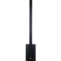


- WORLD HEADQUARTERS
- CANADA
- U.S.A.
- SERVICE MANUAL
- EXM Mobile 12
- SMT Disclaimer
- IMPORTANT SAFETY INSTRUCTIONS
- Power Sources
- Hazards
- Power Cord
- Service
- WARNING:
- Block Diagram - EXM 70, EXM Mobile & Mobile12
- DESIGN HISTORY AND INFORMATION
- PCB ASSEMBLY DOCUMENTATION
- SPECIAL PRODUCTION NOTES
- Heatsin Assembly PCB Finis ing
- M1914- EXMmobile12
- IMPORTANT!
- BEFORE WAVE SOLDER
- AFTER WAVE SOLDER
- Channel 1&2 Inputs
- Channel 3 Input
- Bluetooth™
- Channel Level Controls
- Channel Shape Controls
- EXM Mobile EXM Mobile + EXM Mobile12
- Channel Effects Controls
- Master Control
- Effects Selector
- Link Jacks
- Battery Status Indicators
- Low-Power "Sleep" State
- Charging Indicator
- Charging the EXM Mobile
Brand : YORKVILLE
Model : EXM Mobile 12
Category : Loudspeaker