
Excursion Mini EXM70 - Loudspeaker YORKVILLE - Free user manual and instructions
Find the device manual for free Excursion Mini EXM70 YORKVILLE in PDF.
| Product type | Portable powered speaker |
| Brand | Yorkville |
| Model | Excursion Mini EXM70 |
| Power source | AC mains |
| Power | 70 W (estimated) |
| Inputs | 3 channels: 2 combo XLR/Jack (mic/line) with 24V phantom power, 1 XLR mic input + 1/8" jack + Bluetooth |
| Bluetooth | Range up to 10 m (33 ft) |
| Effects | Delay, Hall Reverb, Room Reverb (selectable) |
| Controls | Channel volume, Shape (Music/Speech/Flat), Master, effects selector |
| Link outputs | 2 XLR connectors (male and female) for daisy-chaining |
| Mounting | Built-in standard pole adapter |
| Usage | Indoor use only |
| Cleaning | Dry cloth only |
| Safety | Do not expose to water, do not open, unplug during storms, do not place lit candles |
| Operating temperature | Not specified |
| Included accessories | Not specified (power cord included) |
Frequently Asked Questions - Excursion Mini EXM70 YORKVILLE
User questions about Excursion Mini EXM70 YORKVILLE
0 question about this device. Answer the ones you know or ask your own.
Ask a new question about this device
Download the instructions for your Loudspeaker in PDF format for free! Find your manual Excursion Mini EXM70 - YORKVILLE and take your electronic device back in hand. On this page are published all the documents necessary for the use of your device. Excursion Mini EXM70 by YORKVILLE.
USER MANUAL Excursion Mini EXM70 YORKVILLE
Niagara Falls, New York
14305.USA
Voice: 716-297-2920
Fax:716-297-3689
Quality and Innovation Since 1963
Printed in Canada

SERVICE MANUAL
EXM70
SMT Disclaimer
Due to the complex nature of the use of SMT installed components in Yorkville equipment, we highly caution all service technicians in attempting to repair or replace SMT factory installed components.
Many of these components may be glued prior to initial soldering.
Replacing SMT components requires expensive
specialized de-soldering equipment and training
Yorkville Sound will repair and replace defective SMT components to ensure proper quality assurance and installation is maintained.
Manual-Service-EXM70-03-1v9·January 24, 2024
IMPORTANT SAFETY INSTRUCTIONS

This lightning flash with arrowhead symbol, within an
equilateral triangle, is intended to alert the user to the presence of unregulated 'dangerous voltage' within the product's enclosure that may be of sufficient magnitude to constitute a risk of electric shock to persons.
The DO NOT STACK symbol is intended to alert the user that, the product shall not be vertically stacked because of the nature of the product.
CAUTION: OVERHEAD LOAD
ATTENTION: CHERAGE AERIENNE
FOLLOW ALL INSTRUCTIONS SUVEZ TOUTES LES INSTRUCTIONS
Instructions pertaining to a risk of fire, electric shock, or injury to a person
CAUTION: TO REDUCE THE RISK OF ELECTRIC SHOCK, DO NOT REMOVE COVER (OR BACK).
NO USER SERVICEABLE PARTS INSIDE. REFER SERVICING TO QUALIFIED SERVICE
PERSONNEL. THIS DEVICE IS FOR INDOOR USE ONLY!
INSTALLED BATTERY PACKS SHALL NOT BE EXPOSED TO EXCESSIVE HEAT
SUCH AS SUNSHINE, FIRE OR THE LIKE
Read Instructions: The Owner's Manual should be read and understood before operation of your unit. Please, save these instructions for future
alereence and heed all warnings.
Cleaning: Clean only with dry cloth.
Packaging: Keep the box and packaging materials, in case the unit needs to be returned for service.
Warning: To reduce the risk or fire or electric shock, do not expce this aporatus to rain or moisture. Do not use this apocaratus near water!
Warning: When using electric products, basic precautions should always be followed, including the following:
Power Sources
Your unit should be connected to a power source only of the voltage specified in the owners manual or as marked on the unit. This unit has a polarized plug. Do not use with an extension card or receptacle unless the plug can be fully inserted. Precautions should be taken so that the grounding scheme on the unit is not defective. An apparatus with CLASS I construction shall be connected to a Mains socket outlet with a protective surfacing connection. Where the MAINS plug or an appliance coupler is used as the disconnect device, the disconnect device shall remain readily operable.
Hazards
Do not place this product on an unstable cart, stand, tripod, bracket or table. The product may fail, causing serious personal injury and serious damage to the product. Use only with cart, stand, tripod, bracket, or table recommended by the manufacturer or sold with the product. Follow the manufacturer's instructions when installing the product and use mounting accessories recommended by the manufacturer. Only use attachments/accessories specified by the manufacturer.
Equipment that is suspended overhead must use a secondary safeguard to prevent personal injury in the event the primary mounting mechanism fails. Safety eyebolts attached to the equipment and gavanized steel wire can be used together to implement a falsafe mounting thus ensuring the safety of the equipment and anyone positioned below the equipment.
Improper installation can result in bodily injury or death. If you are not qualified to attempt the installation get help from a professional structural rigger. Notes: Prolonged use of headphones at a high volume may cause badly damage to your ears.
The apparatus should not be exposed to dripping or splashing water, no objects filled with liquids should be placed on the apparatus.
Terminals marked in the 'lightning bolt' are hazardous live; the external wiring connected to these terminals require installation by an instructed person or the use of ready made leads or cords.
Ensure that proper ventilation is provided around the appliance. Do not install near any heat sources such as radiators, heat registers, stoves, or other apparatus (including amplifiers) that produce heat.
No raked farnes sources, such as lighted candelis, should be placed on the apparatus.
Power Cord
Do not defeat the safety purpose of the polarized or grounding-type plug. A polarized plug has two blades with one wider than the other. A grounding type plug has two blades and a third grounding plug. The wide blade or the third plug are provided for your safety. If the provided plug does not fill into your outlet, consult an electrician for replacement of the obsolete outlet. The AC supply cord should be routed so that it is unlikely that it will be damaged. Protect the power cord from being walked on or pinched particularly at plugs. If the AC supply cord is damaged DO NOT OPERATE THE UNIT. To completely disconnect the apparatus from the AC Mains, disconnect the power supply cord plug from the AC receptacle. The mains plug of the power supply cord shall remain readily operable.
Unplug this apparatus during lightning storms or when unused for long periods of time.
Service
The unit should be serviced only by qualified service personnel. Servicing is required when the apparatus has been damaged in any way, such as power-supply cord or plug is damaged, liquid has been spilled or objects have fallen into the apparatus, the apparatus has been exposed to rain or moisture, does not operate normally, requires battery pack replacement or has been dropped. Disconnect power before servicing!
IMPORTANT SAFETY INSTRUCTIONS

The Lightning Flash with arrowhead symbol within an equilateral triangle, is intended to alert the user to the presence of uninsulated "dangerous voltage" within the product enclosure that may be of sufficient magnitude to constitute a risk of shock to persons

The exclamation point within an equilateral triangle is intended to avert the user to the presence of important operating and maintenance (servicing) instructions in the literature accompanying the product
-
Read these instructions.
-
Keep these instructions.
-
Head all warnings.
-
Follow all instructions.
-
Do not use this apparatus near water.
-
Clean polyl with dry silt
-
Do not block any ventilation openings, install in accordance with the manufacturer's instructions.
B. Do not install near any heat sources such as radiators, heat registers, stoves, or other apparatus (including amplifiers) that produce heat
Do not defaet the safery purpose of the polarized or groundin-type plug Apolarized plug has two blades with one witer than the other.A grounding type plug has two blades and a third grounding prong. The wide blade or the third prongs are provided for your safety. If the provided plug does not fit into your oulet, consult an electrician for replacement of the obsoileol outlet.
-
Protect the power cord from being walked on or pinched particularly at plugs, convenience receptacles, and the point where they exit from the apparatus.
-
Only use attachments/accessories specified by the manufacturer.
-
Use only with the cart, stand, tripod, bracket, or table specified by the manufacturer, or sold with the apparatus. When a cert is used, use caution when moving the cert/asperus combination to avoid injury from lip-over.
-
Unplug this apparatus during lightning storms or when unused for long periods of time.
-
Refer all servicing to qualified service personnel. Servicing is required when the apparatus has been damaged in any way, such as power-supply cord or plug is damaged, liquid has been spilled or objects have fallen into the apparatus, the apparatus has been exposed to rain or moisture, does not operate normally, or has been dropped.
WARNING
- To reduce the risk of fire or electric shock, do not expose this apparatus to rain or moisture and objects filled with liquids, such as vases, should not be placed on this apparatus.
To completely disconnect this apparatus from the ac mains, disconnect the power supply cord plug from the ac receptacle.
The mains plug of the power supply cord or appliance coupler shall remain readily accessible.

| Specifications | |||
| EXM 70 EXM Mobile EXM Mobiles12 | |||
| Program Power (watts) | 60 watts 60 watts 60 watts | ||
| Max SPL (dB) | 115-115 120 Continuous (126 Peak) | ||
| Frequency Response (Hz +/- 3db) | 90-20k 70-20k 65-18k | ||
| Speaker Configuration - LF | 2 x 6.5-inch (2 x 5-inch pre-2020) 2 x 6.5-inch 12 inch | ||
| Speaker Configuration - HF | 1-inch Soft Dome 1-inch Soft Dome 1 inch exit compression driver | ||
| Inputs | 3 3 3 | ||
| Channel 1 Input | XLR / ¼-inch Combi-jack | XLR / ¼-inch Combi-jack | XLR / ¼-inch Combi-jack |
| Channel 1 Controls | Level, Shape, Effects Send | Level, Shape, Effects Send | Level, Shape, Effects Send |
| Channel 2 Input | XLR / ¼-inch Combi-jack | XLR / ¼-inch Combi-jack | XLR / ¼-inch Combi-jack |
| Channel 2 Controls | Level, Shape, Effects Send | Level, Shape, Effects Send | Level, Shape, Effects Send |
| Channel 3 Input | XLR Mic & 1/8-inch TRS Stereo Jack, BluetoothTM | XLR Mic & 1/8-inch TRS Stereo Jack, BluetoothTM | XLR Mic & 1/8-inch TRS Stereo Jack, BluetoothTM |
| Channel 3 Controls | Level, Shape, Effects Send, Bluetooth | Level, Shape, Effects Send, BluetoothTM | Level, Shape, Effects Send, BluetoothTM |
| Master Volume Control | Yes Yes | Yes | |
| Link In/Out (type / configuration) | XLR Connector (Male and Female) | XLR Connector (Male and Female) | XLR Connector (Male and Female) |
| LED Indicators | Power, Clip (CH1, CH2, CH3), Bluetooth | Power, Clip (CH1, CH2, CH3), Bluetooth, 4x Battery Level, Charging Status | Power, Clip (CH1, CH2, CH3), Bluetooth, 4x Battery Level, Charging Status |
| Other Features | Digital Effects (Hall Reverb, Room Reverb and Delay) | Digital Effects (Hall Reverb, Room Reverb and Delay) | Digital Effects (Hall Reverb, Room Reverb and Delay) |
| Power Consumption while charging (watts) | N/A | 32 (battery fully discharged and unit idle) | 32 (battery fully discharged and unit idle) |
| Dimensions (DWH, Inches) | 8 x 7.75 x 17.5 | 8 x 7.75 x 17.5 | 23.5 x 13.5 x 11.5 |
| Dimensions (DWH, cm) | 20.25 x 19.7 x 44.5 | 20.25 x 19.7 x 44.5 | 59.5 x 34 x 29 |
| Weight (lbs/kg) | 16.3 / 7.4 (14.4 / 6.5 pre-2020) | 17.8 / 8.0 | 33.4 / 15.1 |
Specifications subject to change without notice
| ExM 70 EXM MOBILE EXM Mobiles12 | Spécifications | ||
| Puisance programme (watts) | 60 watts 60 watts | 60 watts | 60 watts |
| Max SPL (dB) | 115 115 | 120dB Continuous (128 Peak) | |
| Réponse en Fréquence (Hz +/- 3dB) | 90-20k 70-20k 65-18k | ||
| Configuration haut-parleur - Entrées | 2 x 6.5-pouce (2 x 5-pouce avant-2020) | 2 x 6.5-pouce | 12-pouce |
| Configuration des haut-parleurs - HF | Dôme souple de 1 pouce Dôme souple de 1 pouce | Dôme souple de 1 pouce | |
| Entrées | 3 | 3 | 3 |
| Entrée du canal 1 | XLR / ¼ de pouce Combi-jack XLR / ¼ de pouce Combi-jack | XLR / ¼ de pouce Combi-jack | |
| Commande du canal 1 | Level, Shape, Effects | Level, Shape, Effects | Level, Shape, Effects |
| Entrée du canal 2 | XLR / ¼ de pouce Combi-jack XLR / ¼ de pouce Combi-jack | XLR / ¼ de pouce Combi-jack | |
| Commande du canal 2 | Level, Shape, Effects Send Level, Shape, Effects Send | Level, Shape, Effects Send | |
| Entrée du canal 3 | XLR et Jack stériso 1/8-pouce stériso, BluetoothTM | XLR et Jack stériso 1/8-pouce stériso, BluetoothTM | |
| Commande du canal 3 | Level, Shape, Effects, Bluetooth Level, Shape, Effects, BluetoothTM | Level, Shape, Effects, BluetoothTM | |
| Master Volume Control | Oui Ou | Oui | |
| Entrée / Sortie Link (type / configuration) | Connecteur XLR Connecteur XLR | XLR Connector (Male and Female) | |
| Indicateurs DEL | Alimentation, C1, C2, C3 & Effect Clip, Master Clip | Alimentation, Clip (CH1, CH2, CH3), Bluetooth, Niveau de batterie 4x, État de charge | Power, Clip (CH1, CH2, CH3), Bluetooth, 4x Battery Level, Charging Status |
| Autres caractéristiques | Effets numériques (Hall Reverb, Room Reverb and Delay) | Effets numériques (Hall Reverb, Room Reverb and Delay) | Effets numériques (Hall Reverb, Room Reverb and Delavi) |
| Consommation pendant la charge (watts) | N/A | 32 (battery complètement décharge et au repos) | 32 (battery complètement décharge et au repos) |
| Dimensions (PLH, pouces) | 8 x 7.75 x 17.5 | 8 x 7.75 x 17.5 | 23.5 x 13.5 x 11.5 |
| Dimensions (DWH, cm) | 20.25 x 19.7 x 44.5 | 20.25 x 19.7 x 44.5 | 59.5 x 34 x 29 |
| Poids (lb / kg) | 16.3 / 7.4 (14.4 / 6.5 avant-2020) | 17.8 / 8.0 | 33.4 / 15.1 |
Spcifications sujettes a changement sans preavis
M1614 1of2 Parts Reference List 8/31/2018
| REF | YS# | Description | REF | YS# | Description | REF | YS# | Description | REF | YS# | Description | REF | YS# | Description |
| A-25 | M16H4-F-S | KSTV MIN PGR | C25 | 838 | 4U | 6W BYSCAP TAC EXTMI, ZF | 1134 | 696 | UTT 100W 2XPCAP TAC RAD 1 FDR | 271 | 2355 44X375WY VION STANDOFF NUT | 2014 | W125 100K 5% | 0.005 SMT DFT |
| A-25 | 5281 | 4U | 631 | 22U | 5W BYSCAP TAC EXTMI, ZF | 1135 | 100 | 100V 100SAP 120M XRT | 292 | 2355 44X375WY VION STANDOFF NUT | 2012 | W125 100K 5% | 0.005 SMT DFT | |
| A-25 | 5381 | 2U | 634 | 22B | 4U | 6W BYSCAP TAC EXTMI, ZF | 1136 | 100 | 100V 100SAP 120M XRT | 292 | 2355 44X375WY VION STANDOFF NUT | 2012 | W125 100K 5% | 0.005 SMT DFT |
| A-25 | 5381 | 2U | 634 | 22B | 100 | 6W BYSCAP TAC EXTMI, ZF | 1137 | 100 | 100V 100SAP 120M XRT | 292 | 2355 44X375WY VION STANDOFF NUT | 2012 | W125 100K 5% | 0.005 SMT DFT |
| A-25 | 5381 | 2U | 634 | 22B | 2U | 6W BYSCAP TAC EXTMI, ZF | 1138 | 100 | 100V 100SAP 120M XRT | 292 | 2355 44X375WY VION STANDOFF NUT | 2012 | W125 100K 5% | 0.005 SMT DFT |
| A-25 | 5381 | 2U | 634 | 22B | 3U | 6W BYSCAP TAC EXTMI, ZF | 1139 | 100 | 100V 100SAP 120M XRT | 292 | 2355 44X375WY VION STANDOFF NUT | 2012 | W125 100K 5% | 0.005 SMT DFT |
| A-25 | 5381 | 2U | 634 | 22B | 5U | 6W BYSCAP TAC EXTMI, ZF | 1140 | 100 | 100V 100SAP 120M XRT | 292 | 2355 44X375WY VION STANDOFF NUT | 2012 | W125 100K 5% | 0.005 SMT DFT |
| A-25 | 5381 | 2U | 634 | 22B | 6U | 6W BYSCAP TAC EXTMI, ZF | 1141 | 100 | 100V 100SAP 120M XRT | 292 | 2355 44X375WY VION STANDOFF NUT | 2012 | W125 100K 5% | 0.005 SMT DFT |
| A-25 | 5381 | 2U | 634 | 22B | 7U | 6W BYSCAP TAC EXTMI, ZF | 1142 | 100 | 100V 100SAP 120M XRT | 292 | 2355 44X375WY VION STANDOFF NUT | 2012 | W125 100K 5% | 0.005 SMT DFT |
| A-25 | 5381 | 2U | 634 | 22B | 8U | 6W BYSCAP TAC EXTMI, ZF | 1143 | 100 | 100V 100SAP 120M XRT | 292 | 2355 44X375WY VION STANDOFF NUT | 2012 | W125 100K 5% | 0.005 SMT DFT |
| A-25 | 5381 | 2U | 634 | 22B | 9U | 6W BYSCAP TAC EXTMI, ZF | 1144 | 100 | 100V 100SAP 120M XRT | 292 | 2355 44X375WY VION STANDOFF NUT | 2012 | W125 100K 5% | 0.005 SMT DFT |
| A-25 | 5381 | 2U | 634 | 22B | 0U | 6W BYSCAP TAC EXTMI, ZF | 1145 | 100 | 100V 100SAP 120M XRT | 292 | 2355 44X375WY VION STANDOFF NUT | 2012 | W125 100K 5% | 0.005 SMT DFT |
| A-25 | 5381 | 2U | 634 | 22B | ||||||||||
| A-25 | 5381 | 2U | 634 | 22B | ||||||||||
| A-25 | 5381 | 2U | 634 | 22B | ||||||||||
| A-25 | 5381 | 2U | 634 | 22B | ||||||||||
| B-1 | 5381 | 2U | 634 | 22B | 0U | 6W BYSCAP TAC EXTMI, ZF | 1146 | 100 | 100V 100SAP 120M XRT | 292 | 2355 44X375WY VION STANDOFF NUT | 2012 | W125 100K 5% | 0.005 SMT DFT |
| B-1 | 5381 | 2U | 634 | 22B | 1U | 6W BYSCAP TAC EXTMI, ZF | 1147 | 100 | 100V 100SAP 120M XRT | 292 | 2355 44X375WY VION STANDOFF NUT | 2012 | W125 100K 5% | 0.005 SMT DFT |
| B-1 | 5381 | 2U | 634 | 22B | 2U | 6W BYSCAP TAC EXTMI, ZF | 1148 | 100 | 100V 100SAP 120M XRT | 292 | 2355 44X375WY VION STANDOFF NUT | 2012 | W125 100K 5% | 0.005 SMT DFT |
| B-1 | 5381 | 2U | 634 | 22B | 3U | 6W BYSCAP TAC EXTMI, ZF | 1149 | 100 | 100V 100SAP 120M XRT | 292 | 2355 44X375WY VION STANDOFF NUT | 2012 | W125 100K 5% | 0.005 SMT DFT |
| B-1 | 5381 | 2U | 634 | 22B | 4U | 6W BYSCAP TAC EXTMI, ZF | 1150 | 100 | 100V 100SAP 120M XRT | 292 | 2355 44X375WY VION STANDOFF NUT | 2012 | W125 100K 5% | 0.005 SMT DFT |
| B-1 | 5381 | 2U | 634 | 22B | 5U | 6W BYSCAP TAC EXTMI, ZF | 1151 | 100 | 100V 100SAP 120M XRT | 292 | 2355 44X375WY VION STANDOFF NUT | 2012 | W125 100K 5% | 0.005 SMT DFT |
| B-1 | 5381 | 2U | 634 | 22B | 6U | 6W BYSCAP TAC EXTMI, ZF | 1152 | 100 | 100V 100SAP 120M XRT | 292 | 2355 44X375WY VION STANDOFF NUT | 2012 | W125 100K 5% | 0.005 SMT DFT |
| B-1 | 5381 | 2U | 634 | 22B | 7U | 6W BYSCAP TAC EXTMI, ZF | 1153 | 100 | 100V 100SAP 120M XRT | 292 | 2355 44X375WY VION STANDOFF NUT | 2012 | W125 100K 5% | 0.005 SMT DFT |
| B-1 | 5381 | 2U | 634 | 22B | 8U | 6W BYSCAP TAC EXTMI, ZF | 1154 | 100 | 100V 100SAP 120M XRT | 292 | 2355 44X375WY VION STANDOFF NUT | 2012 | W125 100K 5% | 0.005 SMT DFT |
| B-1 | 5381 | 2U | 634 | 22B | 9U | 6W BYSCAP TAC EXTMI, ZF | 1155 | 100 | 100V 100SAP 120M XRT | 292 | 2355 44X375WY VION STANDOFF NUT | 2012 | W125 100K 5% | 0.005 SMT DFT |
| B-1 | 5381 | 2U | 634 | 22B | 10U | 6W BYSCAP TAC EXTMI, ZF | 1156 | 100 | 100V 100SAP 120M XRT | 292 | 2355 44X375WY VION STANDOFF NUT | 2012 | W125 100K 5% | 0.005 SMT DFT |
| B-1 | 5381 | 2U | 634 | 22B | 20U | 6W BYSCAP TAC EXTMI, ZF | 1157 | 100 | 100V 100SAP 120M XRT | 292 | 2355 44X375WY VION STANDOFF NUT | 2012 | W125 100K 5% | 0.005 SMT DFT |
| B-1 | 5381 | 2U | 634 | 22B | 30U | 6W BYSCAP TAC EXTMI, ZF | 1158 | 100 | 100V 100SAP 120M XRT | 292 | 2355 44X375WY VION STANDOFF NUT | 2012 | W125 100K 5% | 0.005 SMT DFT |
| B-1 | 5381 | 2U | 634 | 22B | 40U | 6W BYSCAP TAC EXTMI, ZF | 1160 | 100 | 100V 100SAP 120M XRT | 292 | 2355 44X375WY VION STANDOFF NUT | 2012 | W125 100K 5% | 0.005 SMT DFT |
| B-1 | 5381 | 2U | 634 | 22B | 45U | 6W BYSCAP TAC EXTMI, ZF | 1171 | 100 | 100V 100SAP 120M XRT | 292 | 2355 44X375WY VION STANDOFF NUT | 2012 | W125 100K 5% | 0.005 SMT DFT |
| B-1 | 5381 | 2U | 634 | 22B | 55U | 6W BYSCAP TAC EXTMI, ZF | 1172 | 100 | 100V 100SAP 120M XRT | 292 | 2355 44X375WY VION STANDOFF NUT | 2012 | W125 100K 5% | 0.005 SMT DFT |
| B-1 | 5381 | 2U | 634 | 22B | 65U | 6W BYSCAP TAC EXTMI, ZF | 1173 | 100 | 100V 100SAP 120M XRT | 292 | 2355 44X375WY VION STANDOFF NUT | 2012 | W125 100K 5% | 0.005 SMT DFT |
| B-1 | 5381 | 2U | 634 | 22B | 75U | 6W BYSCAP TAC EXTMI, ZF | 1174 | 100 | 100V 100SAP 120M XRT | 292 | 2355 44X375WY VION STANDOFF NUT | 2012 | W125 100K 5% | 0.005 SMT DFT |
| B-1 | 5381 | 2U | 634 | 22B | 85U | 6W BYSCAP TAC EXTMI, ZF | 1175 | 100 | 100V 100SAP 120M XRT | 292 | 2355 44X375WY VION STANDOFF NUT | 2012 | W125 100K 5% | 0.005 SMT DFT |
| B-1 | 5381 | 2U | 634 | 22B | 95U | 6W BYSCAP TAC EXTMI, ZF | 1176 | 100 | 100V 100SAP 120M XRT | 292 | 2355 44X375WY VION STANDOFF NUT | 2012 | W125 100K 5% | 0.005 SMT DFT |
| B-1 | 5381 | 2U | 634 | 22B | 96U | 6W BYSCAP TAC EXTMI, ZF | 1177 | 100 | 100V 100SAP 120M XRT | 292 | 2355 44X375WY VION STANDOFF NUT | 2012 | W125 100K 5% | 0.005 SMT DFT |
| B-1 | 5381 | 2U | 634 | 22B | 115U | 6W BYSCAP TAC EXTMI, ZF | 1178 | 100 | 100V 100SAP 120M XRT | 292 | 2355 44X375WY VION STANDOFF NUT | 2012 | W125 100K 5% | 0.005 SMT DFT |
| B-1 | 5381 | 2U | 634 | 22B | 125U | 6W BYSCAP TAC EXTMI, ZF | 1179 | 100 | 100V 100SAP 120M XRT | 292 | 2355 44X375WY VION STANDOFF NUT | 2012 | W125 100K 5% | 0.005 SMT DFT |
| B-1 | 5381 | 2U | 634 | 22B | 135U | 6W BYSCAP TAC EXTMI, ZF | 1180 | 100 | 100V 100SAP 120M XRT | 292 | 2355 44X375WY VION STANDOFF NUT | 2012 | W125 100K 5% | 0.005 SMT DFT |
| B-1 | 5381 | 2U | 634 | 22B | 145U | 6W BYSCAP TAC EXTMI, ZF | 1181 | 100 | 100V 100SAP 120M XRT | 292 | 2355 44X375WY VION STANDOFF NUT | 2012 | W125 100K 5% | 0.005 SMT DFT |
| B-1 | 5381 | 2U | 634 | 22B | 155U | 6W BYSCAP TAC EXTMI, ZF | 1182 | 100 | 100V 100SAP 120M XRT | 292 | 2355 44X375WY VION STANDOFF NUT | 2012 | W125 100K 5% | 0.005 SMT DFT |
| B-1 | 5381 | 2U | 634 | 22B | 165U | 6W BYSCAP TAC EXTMI, ZF | 1183 | 100 | 100V 100SAP 120M XRT | 292 | 2355 44X375WY VION STANDOFF NUT | 2012 | W125 100K 5% | 0.005 SMT DFT |
| B-1 | 5381 | 2U | 634 | 22B | 175U | 6W BYSCAP TAC EXTMI, ZF | 1184 | 100 | 100V 100SAP 120M XRT | 292 | 2355 44X375WY VION STANDOFF NUT | 2012 | W125 100K 5% | 0.005 SMT DFT |
| B-1 | 5381 | 2U | 634 | 22B | 185U | 6W BYSCAP TAC EXTMI, ZF | 1185 | 100 | 100V 100SAP 120M XRT | 292 | 2355 44X375WY VION STANDOFF NUT | 2012 | W125 100K 5% | 0.005 SMT DFT |
| B-1 | 5381 | 2U | 634 | 22B | 235U | 6W BYSCAP TAC EXTMI, ZF | 1186 | 100 | 100V 100SAP 120M XRT | 292 | 2355 44X375WY VION STANDOFF NUT | 2012 | W125 100K 5% | 0.005 SMT DFT |
| B-1 | 5381 | 2U | 634 | 22B | 345U | 6W BYSCAP TAC EXTMI, ZF | 1187 | 100 | 100V 100SAP 120M XRT | 292 | 2355 44X375WY VION STANDOFF NUT | 2012 | W125 100K 5% | 0.005 SMT DFT |
| B-1 | 5381 | 2U | 634 | 22B | 435U | 6W BYSCAP TAC EXTMI, ZF | 1188 | 100 | 100V 100SAP 120M XRT | 292 | 2355 44X375WY VION STANDOFF NUT | 2012 | W125 100K 5% | 0.005 SMT DFT |
| B-1 | 5381 | 2U | 634 | 22B | 545U | 6W BYSCAP TAC EXTMI, ZF | 1189 | 100 | 100V 100SAP 120M XRT | 292 | 2355 44X375WY VION STANDOFF NUT | 2012 | W125 100K 5% | 0.005 SMT DFT |
| B-1 | 5381 | 2U | 634 | 22B | 645U | 6W BYSCAP TAC EXTMI, ZF | 1190 | 100 | 100V 100SAP 120M XRT | 292 | 2355 44X375WY VION STANDOFF NUT | 2012 | W125 100K 5% | 0.005 SMT DFT |
| B-1 | 5381 | 2U | 634 | 22B | 745U | 6W BYSCAP TAC EXTMI, ZF | 1191 | 100 | 100V 100SAP 120M XRT | 292 | 2355 44X375WY VION STANDOFF NUT | 2012 | W125 100K 5% | 0.005 SMT DFT |
| B-1 | 5381 | 2U | 634 | 22B | 845U | 6W BYSCAP TAC EXTMI, ZF | 1192 | 100 | 100V 100SAP 120M XRT | 292 | 2355 44X375WY VION STANDOFF NUT | 2012 | W125 100K 5% | 0.005 SMT DFT |
| B-1 | 5381 | 2U | 634 | 22B | 945U | 6W BYSCAP TAC EXTMI, ZF | 1193 | 100 | 100V 100SAP 120M XRT | 292 | 2355 44X375WY VION STANDOFF NUT | 2012 | W125 100K 5% | 0.005 SMT DFT |
| B-1 | 5381 | 2U | 634 | 22B | 985U | 6W BYSCAP TAC EXTMI, ZF | 1194 | 100 | 100V 100SAP 120M XRT | 292 | 2355 44X375WY VION STANDOFF NUT | 2012 | W125 100K 5% | 0.005 SMT DFT |
| B-1 | 5381 | 2U | 634 | 22B | 795U | 6W BYSCAP TAC EXTMI, ZF | 1195 | 100 | 100V 100SAP 120M XRT | 292 | 2355 44X375WY VION STANDOFF NUT | 2012 | W125 100K 5% | 0.005 SMT DFT |
| REF YS # Description REF YS # Description |
| R78B W128 249RO 1% 0805 SMT RES R127 W104 475K 1% 0805 SMT RES R219 W104 2K74 1% 0805 SMT RES |
| R77C W129 249RO 1% 0805 SMT RES R123 W128 562RO 1% 0805 SMT RES R220 W108 2K74 1% 0805 SMT RES |
| R58A W125 562RO 1% 0805 SMT RES R129 W100 2K74 1% 0805 SMT RES R221 W100 1K0 1% 0805 SMT RES |
| R58B W125 562RO 1% 0805 SMT RES R130 W100 1K0 1% 0805 SMT RES R222 W100 4K99 1% 0805 SMT RES |
| R58C W125 562RO 1% 0805 SMT RES R131 W100 4K99 1% 0805 SMT RES R223 W100 4K99 1% 0805 SMT RES |
| R59A W100 4K99 1% 0805 SMT RES R132 W100 2K74 1% 0805 SMT RES R224 W100 4K99 1% 0805 SMT RES |
| R59B W100 4K99 1% 0805 SMT RES R135 W100 1M50 1% 0805 SMT RES R225 W100 4K95 1% 0805 SMT RES |
| R59C W100 4K99 1% 0805 SMT RES R136 W100 15K0 1% 0805 SMT RES R228 W100 10K0 1% 0805 SMT RES |
| R60A W128 8K25 1% 0805 SMT RES R137 W128 10K0 5% 0805 SMT RES R232 W100 1K0 1% 0805 SMT RES |
| R60B W128 8K25 1% 0805 SMT RES R138 W128 15M0 1% 0805 SMT RES R233 W100 1K0 1% 0805 SMT RES |
| R60C W128 8K25 1% 0805 SMT RES R139 W128 10K0 5% 0805 SMT RES R234 W100 10K0 1% 0805 SMT RES |
| R61A W100 10K0 1% 0603 SMT RES R140 W128 1K54 1% 0805 SMT RES R235 W128 2K4 5% 0805 SMT RES |
| R61B W100 10K0 1% 0603 SMT RES R141 W128 10K0 5% 1206 SMT RES R236 W128 2K4 5% 0805 SMT RES |
| R61C W100 10K0 1% 0603 SMT RES R142 W128 1W00 47R 5% 2512 SMT RES R237 W128 47R 5% 1206 SMT RES |
| R63 W100 10K0 1% 0603 SMT RES R143 W128 10K0 1% 0805 SMT RES R238 W128 47R 5% 1206 SMT RES |
| R64A W100 6K80 1% 0603 SMT RES R144 W128 10K0 1% 0805 SMT RES R241 W100 4W0 1% 0805 SMT RES |
| R64B W100 6K80 1% 0603 SMT RES R145 W128 22R 5% 2512 SMT RES R242 W100 10R 1% 0805 SMT RES |
| R64C W100 6K80 1% 0603 SMT RES R146 W128 22R 5% 2512 SMT RES R246 2492 FUSE LAG OAA 250V T&R |
| R65A W128 8K25 1% 0805 SMT RES R147 W128 30K 0.5% 0805 SMT RES R249 W128 10R 1% 0805 SMT RES |
| R65B W128 8K25 1% 0805 SMT RES R148 W128 15K0 5% 1206 SMT RES R250 W128 10R 1% 0805 SMT RES |
| R65C W128 8K25 1% 0805 SMT RES R149 W128 15K0 5% 1206 SMT RES R251 W128 1K21 1% 0805 SMT RES |
| R66A W100 4K99 1% 0805 SMT RES R150 W128 22K 5% 0805 SMT RES R252 W100 10K0 1% 0805 SMT RES |
| R66B W100 4K99 1% 0805 SMT RES R151 W128 4K99 1% 0805 SMT RES R253 W100 10K0 1% 0805 SMT RES |
| R66C W100 4K99 1% 0805 SMT RES R152 W100 10K0 1% 0805 SMT RES R254 W100 10K0 1% 0805 SMT RES |
| R67 W100 4K99 1% 0805 SMT RES R153 W100 4K99 1% 0805 SMT RES R255 W100 10K0 1% 0805 SMT RES |
| R68 W100 536R 1% 0603 SMT RES R154 W128 22K 5% 0805 SMT RES R257 W128 4K99 1% 0805 SMT RES |
| R69 W100 475R 1% 0805 SMT RES R155 W128 22K 5% 0805 SMT RES R258 W128 4K99 1% 0805 SMT RES |
| R70 W100 1K0 1% 0805 SMT RES R156 W128 10K0 1% 0805 SMT RES S1 4189 DPAT NONSHORTING VERT ROT SWT |
| R71 W128 3K32 1% 0805 SMT RES R157 W128 249RO 1% 0805 SMT RES S2 3439 DPD MINI PC VERT MOMENTARY |
| R72 W128 1M 5% 0805 SMT RES R158 W128 10K0 1% 0805 SMT RES SPCRIA 4007.9 LED CUSTOM SPACER |
| R73 W128 22K 5% 0805 SMT RES R159 W128 1M 5% 0805 SMT RES SPCRIB 4007.9 LED CUSTOM SPACER |
| R74 W128 3K32 1% 0805 SMT RES R160 W128 1W00 1K0 1% 0805 SMT RES SPCRIC 4007.9 LED CUSTOM SPACER |
| R75 W128 1K54 1% 0805 SMT RES R161 W128 10K0 1% 0805 SMT RES SPCRII 4007.9 LED CUSTOM SPACER |
| R76 W128 1M 5% 0805 SMT RES R163 W128 1W00 1K0 1% 0805 SMT RES SPCRIII 4007.9 LED CUSTOM SPACER |
| R77 W128 3K32 1% 0805 SMT RES R164 W128 22K 5% 0805 SMT RES U1 TL072 DUAL OPAMP SMT SO-8 |
| R78 W128 3K32 1% 0805 SMT RES R166 W128 1W00 10K0 1% 0603 SMT RES U2 LM13700M XCONDUCTANC AMP SMT IC |
| R79 W128 475R 1% 0805 SMT RES R167 W128 2K4 1% 0805 SMT RES U3 TL072 DUAL OPAMP SMT SO-8 |
| R80 W128 4K99 1% 0805 SMT RES R168 W128 249RO 1% 0805 SMT RES U3 3307D DUAL OPAMP SMT SO-8 |
| R81 W128 249RO 1% 0805 SMT RES R169 W128 4K95 1% 0805 SMT RES U4A MC337DQUAD OPAMP SMT SO14 |
| R82 W128 2K74 1% 0805 SMT RES R170 W128 4W00 4K99 1% 0805 SMT RES U4C MC337DQUAD OPAMP SMT SO14 |
| R83A W128 8K25 1% 0805 SMT RES R171 W128 249RO 1% 0805 SMT RES U5 3307D DUAL OPAMP SMT SO-8 |
| R83B W128 8K25 1% 0805 SMT RES R172 W128 8K25 1% 0805 SMT RES U6 MC337DQUAD OPAMP SMT SO14 |
| R83C W128 8K25 1% 0805 SMT RES R173 W128 4K32 1% 0805 SMT RES U7 MC337DQUAD OPAMP SMT SO14 |
| R84 W128 4K99 1% 0805 SMT RES R174 W128 3K92 1% 0805 SMT RES U8 TDA8950TH 2DAMP HSOP-24 SMT |
| R85 W128 1K0 1% 0805 SMT RES R175 W128 1W00 4K99 1% 1206 SMT RES U9 V1000 DIG REVERB SMT IC SO16W |
| R86 W128 10K0 1% 0805 SMT RES R176 W128 1W00 4K99 1% 1206 SMT RES U10 V422D MSTEREO CODEC SMCT IC SSOP-28 |
| R87 W128 4K99 1% 0805 SMT RES R177 W128 2W50 10R 5% 1206 SMT RES U11 MC337D QUAD OPAMP SMT SO14 |
| R88 W128 4K99 1% 0805 SMT RES R178 W128 2W50 10R 5% 1206 SMT RES U12 MC337D DUAL OPAMP SMT SO-8 |
| R89 W128 1K54 1% 0805 SMT RES R179 W128 1W05 39K2 1% 0805 SMT RES U13 MC337D DUAL OPAMP SMT SO-8 |
| R90 W128 4K99 1% 0805 SMT RES R180 W128 3K92 1% 0805 SMT RES U14 MC337D DUAL OPAMP SMT SO-8 |
| R96 W128 10K0 1% 0603 SMT RES R181 W128 1W00 18K2 1% 0805 SMT RES U15 LM13700M XCONDUCTANC AMP SMT IC |
| R97 W128 4W0 5% 0805 SMT RES R182 W128 4W0 5% 1206 SMT RES U16 TCMOS9 RESET SENSE SMT SOT-23B |
| R98 W128 22R 5% 2512 SMT RES R19 W128 1W00 1K0 1% 0805 SMT RES W128 2K4 1% 0805 SMT RES W128 4K99 1% 0805 SMT RES |
| R99 W128 4W0 5% 2512 SMT RES R19 W128 3K90 1% 1206 SMT RES W128 3W38 24 PIN BREAKWAY LOCK .156 |
| R100 W128 4K99 1% 0805 SMT RES R185 W128 2W50 10R 5% 1206 SMT RES W128 3W38 24 PIN BREAKWAY LOCK .156 |
| R102 W128 4W0 5% 2512 SMT RES R186 W128 2W50 10R 5% 1206 SMT RES W128 3W38 24 PIN BREAKWAY LOCK .156 |
| R103 W128 8K25 1% 0805 SMT RES R187 W128 2W50 10R 5% 1206 SMT RES W128 3W38 24 PIN BREAKWAY LOCK .156 |
| R104 W128 4K99 1% 0805 SMT RES R188 W128 2W50 10R 5% 1206 SMT RES W128 3W38 24 PIN BREAKWAY LOCK .156 |
| R105 W128 4K99 1% 0805 SMT RES R189 W128 2W50 10R 5% 1206 SMT RES W128 3W38 24 PIN BREAKWAY LOCK .156 |
| R106 W128 4K99 1% 0805 SMT RES R19 W128 3W38 24 PIN BREAKWAY LOCK .156 |
| R107 W128 2K74 1% 0805 SMT RES R201 W128 2W50 10R 5% 1206 SMT RES W128 3W38 24 PIN BREAKWAY LOCK .156 |
| R109 W128 2K74 1% 0805 SMT RES R201 W128 2W50 10R 5% 1206 SMT RES W128 3W38 24 PIN BREAKWAY LOCK .156 |
| R110 W128 2K74 1% 0805 SMT RES R202 W128 2W50 10R 5% 1206 SMT RES W128 3W38 24 PIN BREAKWAY LOCK .156 |
| R111 W128 2K74 1% 0805 SMT RES R203 W128 2W50 10R 5% 1206 SMT RES W128 3W38 24 PIN BREAKWAY LOCK .156 |
| R112 W128 3K32 1% 0805 SMT RES R204 W128 4W0 1% 0805 SMT RES W128 2W50 10R 5% 1206 SMT RES W128 3W38 24 PIN BREAKWAY LOCK .156 |
| R113 W128 4W0 5% 0805 SMT RES R205 W128 2W50 10R 5% 1206 SMT RES W128 3W38 24 PIN BREAKWAY LOCK .156 |
| R114 W128 4W0 5% 0805 SMT RES R206 A W128 3W38 24 PIN BREAKWAY LOCK .156 |
| R115 W128 4W0 5% 0805 SMT RES R207 W128 4W0 5% 1206 SMT RES W128 3W38 24 PIN BREAKWAY LOCK .156 |
| R116 W128 4K99 1% 0805 SMT RES R208 W128 4W0 5% 1206 SMT RES W128 3W38 24 PIN BREAKWAY LOCK .156 |
| R117 W128 4W0 5% 0805 SMT RES R209 W128 4W0 5% 1206 SMT RES W128 3W38 24 PIN BREAKWAY LOCK .156 |
| R118 W128 4K99 1% 0805 SMT RES R210 W128 4W0 5% 1206 SMT RES W128 3W38 24 PIN BREAKWAY LOCK .156 |
| R120 W128 4W0 5% 0805 SMT RES R211 W128 4W0 5% 1206 SMT RES W128 3W38 24 PIN BREAKWAY LOCK .156 |
| R121 W128 4W0 5% 0805 SMT RES R212 W128 4W0 5% 1206 SMT RES W128 3W38 24 PIN BREAKWAY LOCK .156 |
| R122 W128 4W0 5% 0805 SMT RES R213 W128 4W0 5% 1206 SMT RES W128 3W38 24 PIN BREAKWAY LOCK .156 |
| R124 W128 4W0 5% 0805 SMT RES R215 W128 4W0 5% 1206 SMT RES W128 3W38 24 PIN BREAKWAY LOCK .156 |
| R125 W128 4W0 5% 0805 SMT RES R216 W128 4W0 5% 1206 SMT RES W128 3W38 24 PIN BREAKWAY LOCK .156 |
| R126 W128 4W0 5% 0805 SMT RES R217 W128 4W0 5% 1206 SMT RES W128 3W38 24 PIN BREAKWAY LOCK .156 |
| R127 W128 4W0 5% 0805 SMT RES R218 W128 4W0 5% 1206 SMT RES W128 3W38 24 PIN BREAKWAY LOCK .156 |
| R129 W128 4W0 5% 0805 SMT RES R220 W128 4W0 5% 1206 SMT RES W128 3W38 24 PIN BREAKWAY LOCK .156 |
| R130 W128 4W0 5% 0805 SMT RES R221 W128 4W0 5% 1206 SMT RES W128 3W38 24 PIN BREAKWAY LOCK .156 |
| R132 W128 4W0 5% 0805 SMT RES R222 W128 4W0 5% 1206 SMT RES W128 3W38 24 PIN BREAKWAY LOCK .156 |
| R133 W128 4W0 5% 0805 SMT RES R223 W128 4W0 5% 1206 SMT RES W128 3W38 24 PIN BREAKWAY LOCK .156 |
| R134 W128 4W0 5% 0805 SMT RES R224 W128 4W0 5% 1206 SMT RES W128 3W38 24 PIN BREAKWAY LOCK .156 |
| R135 W128 4W0 5% 0805 SMT RES R225 W128 4W0 5% 1206 SMT RES W128 3W38 24 PIN BREAKWAY LOCK .156 |
| R136 W128 4W0 5% 0805 SMT RES R226 W128 4W0 5% 1206 SMT RES W128 3W38 24 PIN BREAKWAY LOCK .156 |
| R137 W128 4W0 5% 0805 SMT RES R227 W128 4W0 5% 1206 SMT RES W128 3W38 24 PIN BREAKWAY LOCK .156 |
| R138 W128 4W0 5% 0805 SMT RES R228 W128 4W0 5% 1206 SMT RES W128 3W38 24 PIN BREAKWAY LOCK .156 |
| R139 W128 4W0 5% 0805 SMT RES R229 W128 4W0 5% 1206 SMT RES W128 3W38 24 PIN BREAKWAY LOCK .156 |
| R140 W128 4W0 5% 0805 SMT RES R230 W128 4W0 5% 1206 SMT RES W128 3W38 24 PIN BREAKWAY LOCK .156 |
| R141 W128 4W0 5% 0805 SMT RES R231 W128 4W0 5% 1206 SMT RES W128 3W38 24 PIN BREAKWAY LOCK .156 |
| R142 W128 4W0 5% 0805 SMT RES R232 W128 4W0 5% 1206 SMT RES W128 3W38 24 PIN BREAKWAY LOCK .156 |
| R143 W128 4W0 5% 0805 SMT RES R233 W128 4W0 5% 1206 SMT RES W128 3W38 24 PIN BREAKWAY LOCK .156 |
| R144 W128 4W0 5% 0805 SMT RES R234 W128 4W0 5% 1206 SMT RES W128 3W38 24 PIN BREAKWAY LOCK .156 |
| R145 W128 4W0 5% 0805 SMT RES R235 W128 4W0 5% 1206 SMT RES W128 3W38 24 PIN BREAKWAY LOCK .156 |
| R146 W128 4W0 5% 0805 SMT RES R236 W128 4W0 5% 1206 SMT RES W128 3W38 24 PIN BREAKWAY LOCK .156 |
| R147 W128 4W0 5% 0805 SMT RES R237 W128 4W0 5% 1206 SMT RES W128 3W38 24 PIN BREAKWAY LOCK .156 |
| R148 W128 4W0 5% 0805 SMT RES R238 W128 4W0 5% 1206 SMT RES W128 3W38 24 PIN BREAKWAY LOCK .156 |
| R149 W128 4W0 5% 0805 SMT RES R239 W128 4W0 5% 1206 SMT RES W128 3W38 24 PIN BREAKWAY LOCK .156 |
| R150 W128 4W0 5% 0805 SMT RES R240 W128 4W0 5% 1206 SMT RES W128 3W38 24 PIN BREAKWAY LOCK .156 |
| R151 W128 4W0 5% 0805 SMT RES R241 W128 4W0 5% 1206 SMT RES W128 3W38 24 PIN BREAKWAY LOCK .156 |
| R152 W128 4W0 5% 0805 SMT RES R242 W128 4W0 5% 1206 SMT RES W128 3W38 24 PIN BREAKWAY LOCK .156 |
| R153 W128 4W0 5% 0805 SMT RES R243 W128 4W0 5% 1206 SMT RES W128 3W38 24 PIN BREAKWAY LOCK .156 |
| R154 W128 4W0 5% 0805 SMT RES R244 W128 4W0 5% 1206 SMT RES W128 3W38 24 PIN BREAKWAY LOCK .156 |
| R155 W128 4W0 5% 0805 SMT RES R245 W128 4W0 5% 1206 SMT RES W128 3W38 24 PIN BREAKWAY LOCK .156 |
| R156 W128 4W0 5% 0805 SMT RES R246 W128 4W0 5% 1206 SMT RES W128 3W38 24 PIN BREAKWAY LOCK .156 |
| R157 W128 4W0 5% 0805 SMT RES R247 W128 4W0 5% 1206 SMT RES W128 3W38 24 PIN BREAKWAY LOCK .156 |
| R158 W128 4W0 5% 0805 SMT RES R248 W128 4W0 5% 1206 SMT RES W128 3W38 24 PIN BREAKWAY LOCK .156 |
| R159 W128 4W0 5% 0805 SMT RES R249 W128 4W0 5% 1206 SMT RES W128 3W38 24 PIN BREAKWAY LOCK .156 |
| R160 W128 4W0 5% 0805 SMT RES R250 W128 4W0 5% 1206 SMT RES W128 3W38 24 PIN BREAKWAY LOCK .156 |
| R161 W128 4W0 5% 0805 SMT RES R251 W128 4W0 5% 1206 SMT RES W128 3W38 24 PIN BREAKWAY LOCK .156 |
| R162 W128 4W0 5% 0805 SMT RES R252 W128 4W0 5% 1206 SMT RES W128 3W38 24 PIN BREAKWAY LOCK .156 |
| R163 W128 4W0 5% 0805 SMT RES R253 W128 4W0 5% 1206 SMT RES W128 3W38 24 PIN BREAKWAY LOCK .156 |
| R164 W128 4W0 5% 0805 SMT RES R254 W128 4W0 5% 1206 SMT RES W128 3W38 24 PIN BREAKWAY LOCK .156 |
| R165 W128 4W0 5% 0805 SMT RES R255 W128 4W0 5% 1206 SMT RES W128 3W38 24 PIN BREAKWAY LOCK .156 |
| R166 W128 4W0 5% 0805 SMT RES R256 W128 4W0 5% 1206 SMT RES W128 3W38 24 PIN BREAKWAY LOCK .156 |
| R167 W128 4W0 5% 0805 SMT RES R257 W128 4W0 5% 1206 SMT RES W128 3W38 24 PIN BREAKWAY LOCK .156 |
| R168 W128 4W0 5% 0805 SMT RES R258 W128 4W0 5% 1206 SMT RES W128 3W38 24 PIN BREAKWAY LOCK .156 |
| R169 W128 4W0 5% 0805 SMT RES R259 W128 4W0 5% 1206 SMT RES W128 3W38 24 PIN BREAKWAY LOCK .156 |
| R170 W128 4W0 5% 0805 SMT RES R260 W128 4W0 5% 1206 SMT RES W128 3W38 24 PIN BREAKWAY LOCK .156 |
| R171 W128 4W0 5% 0805 SMT RES R261 W128 4W0 5% 1206 SMT RES W128 3W38 24 PIN BREAKWAY LOCK .156 |
| R172 W128 4W0 5% 0805 SMT RES R262 W128 4W0 5% 1206 SMT RES W128 3W38 24 PIN BREAKWAY LOCK .156 |
| R173 W128 4W0 5% 0805 SMT RES R263 W128 4W0 5% 1206 SMT RES W128 3W38 24 PIN BREAKWAY LOCK .156 |
| R174 W128 4W0 5% 0805 SMT RES R264 W128 4W0 5% 1206 SMT RES W128 3W38 24 PIN BREAKWAY LOCK .156 |
| R175 W128 4W0 5% 0805 SMT RES R265 W128 4W0 5% 1206 SMT RES W128 3W38 24 PIN BREAKWAY LOCK .156 |
| R176 W128 4W0 5% 0805 SMT RES R266 W128 4W0 5% 1206 SMT RES W128 3W38 24 PIN BREAKWAY LOCK .156 |
| R177 W128 4W0 5% 0805 SMT RES R267 W128 4W0 5% 1206 SMT RES W128 3W38 24 PIN BREAKWAY LOCK .156 |
| R178 W128 4W0 5% 0805 SMT RES R268 W128 4W0 5% 1206 SMT RES W128 3W38 24 PIN BREAKWAY LOCK .156 |
| R179 W128 4W0 5% 0805 SMT RES R269 W128 4W0 5% 1206 SMT RES W128 3W38 24 PIN BREAKWAY LOCK .156 |
| R179 W128 4W0 5% 0805 SMT RES R270 W128 4W0 5% 1206 SMT RES W128 3W38 24 PIN BREAKWAY LOCK .156 |
| R179 W128 4W0 5% 0805 SMT RES R271 W128 4W0 5% 1206 SMT RES W128 3W38 24 PIN BREAKWAY LOCK .156 |
| R179 W128 4W0 5% 0805 SMT RES R272 W128 4W0 5% 1206 SMT RES W128 3W38 24 PIN BREAKWAY LOCK .156 |
| R179 W128 4W0 5% 0805 SMT RES R273 W128 4W0 5% 1206 SMT RES W128 3W38 24 PIN BREAKWAY LOCK .156 |
| R179 W128 4W0 5% 0805 SMT RES R274 W128 4W0 5% 1206 SMT RES W128 3W38 24 PIN BREAKWAY LOCK .156 |
| R179 W128 4W0 5% 0805 SMT RES R275 W128 4W0 5% 1206 SMT RES W128 3W38 24 PIN BREAKWAY LOCK .156 |
| R179 W128 4W0 5% 0805 SMT RES R276 W128 4W0 5% 1206 SMT RES W128 3W38 24 PIN BREAKWAY LOCK .156 |
| R179 W128 4W0 5% 0805 SMT RES R277 W128 4W0 5% 1206 SMT RES W128 3W38 24 PIN BREAKWAY LOCK .156 |
| R179 W128 4W0 5% 0805 SMT RES R278 W128 4W0 5% 1206 SMT RES W128 3W38 24 PIN BREAKWAY LOCK .156 |
| R179 W128 4W0 5% 0805 SMT RES R279 W128 4W0 5% 1206 SMT RES W128 3W38 24 PIN BREAKWAY LOCK .156 |
| R179 W128 4W0 5% 0805 SMT RES R280 W128 4W0 5% 1206 SMT RES W128 3W38 24 PIN BREAKWAY LOCK .156 |
| R179 W128 4W0 5% 0805 SMT RES R281 W128 4W0 5% 1206 SMT RES W128 3W38 24 PIN BREAKWAY LOCK .156 |
| R179 W128 4W0 5% 0805 SMT RES R282 W128 4W0 5% 1206 SMT RES W128 3W38 24 PIN BREAKWAY LOCK .156 |
| R179 W128 4W0 5% 0805 SMT RES R283 W128 4W0 5% 1206 SMT RES W128 3W38 24 PIN BREAKWAY LOCK .156 |
| R179 W128 4W0 5% 0805 SMT RES R284 W128 4W0 5% 1206 SMT RES W128 3W38 24 PIN BREAKWAY LOCK .156 |
| R179 W128 4W0 5% 0805 SMT RES R285 W128 4W0 5% 1206 SMT RES W128 3W38 24 PIN BREAKWAY LOCK .156 |
| R179 W128 4W0 5% 0805 SMT RES R286 W128 4W0 5% 1206 SMT RES W128 3W38 24 PIN BREAKWAY LOCK .156 |
| R179 W128 4W0 5% 0805 SMT RES R287 W128 4W0 5% 1206 SMT RES W128 3W38 24 PIN BREAKWAY LOCK .156 |
| R179 W128 4W0 5% 0805 SMT RES R288 W128 4W0 5% 1206 SMT RES W128 3W38 24 PIN BREAKWAY LOCK .156 |
| R179 W128 4W0 5% 0805 SMT RES R289 W128 4W0 5% 1206 SMT RES W128 3W38 24 PIN BREAKWAY LOCK .156 |
| R179 W128 4W0 5% 0805 SMT RES R290 W128 4W0 5% 1206 SMT RES W128 3W38 24 PIN BREAKWAY LOCK .156 |
| R179 W128 4W0 5% 0805 SMT RES R291 W128 4W0 5% 1206 SMT RES W128 3W38 24 PIN BREAKWAY LOCK .156 |
| R179 W128 4W0 5% 0805 SMT RES R292 W128 4W0 5% 1206 SMT RES W128 3W38 24 PIN BREAKWAY LOCK .156 |
| R179 W128 4W0 5% 0805 SMT RES R293 W128 4W0 5% 1206 SMT RES W128 3W38 24 PIN BREAKWAY LOCK .156 |
| R179 W128 4W0 5% 0805 SMT RES R294 W128 4W0 5% 1206 SMT RES W128 3W38 24 PIN BREAKWAY LOCK .156 |
| R179 W128 4W0 5% 0805 SMT RES R295 W128 4W0 5% 1206 SMT RES W128 3W38 24 PIN BREAKWAY LOCK .156 |
| R179 W128 4W0 5% 0805 SMT RES R296 W128 4W0 5% 1206 SMT RES W128 3W38 24 PIN BREAKWAY LOCK .156 |
| R179 W128 4W0 5% 0805 SMT RES R300 W128 4W0 5% 1206 SMT RES W128 3W38 24 PIN BREAKWAY LOCK .156 |
| R179 W128 4W0 5% 0805 SMT RES R301 W128 4W0 5% 1206 SMT RES W128 3W38 24 PIN BREAKWAY LOCK .156 |
| R179 W128 4W0 5% 0805 SMT RES R302 W128 4W0 5% 1206 SMT RES W128 3W38 24 PIN BREAKWAY LOCK .156 |
| R179 W128 4W0 5% 0805 SMT RES R303 W128 4W0 5% 1206 SMT RES W128 3W38 24 PIN BREAKWAY LOCK .156 |
| R179 W128 4W0 5% 0805 SMT RES R304 W128 4W0 5% 1206 SMT RES W128 3W38 24 PIN BREAKWAY LOCK .156 |
| R179 W128 4W0 5% 0805 SMT RES R305 W128 4W0 5% 1206 SMT RES W128 3W38 24 PIN BREAKWAY LOCK .156 |
| R179 W128 4W0 5% 0805 SMT RES R306 W128 4W0 5% 1206 SMT RES W128 3W38 24 PIN BREAKWAY LOCK .156 |
| R179 W128 4W0 5% 0805 SMT RES R307 W128 4W0 5% 1206 SMT RES W128 3W38 24 PIN BREAKWAY LOCK .156 |
| R179 W128 4W0 5% 0805 SMT RES R308 W128 4W0 5% 1206 SMT RES W128 3W38 24 PIN BREAKWAY LOCK .156 |
| R179 W128 4W0 5% 0805 SMT RES R309 W128 4W0 5% 1206 SMT RES W128 3W38 24 PIN BREAKWAY LOCK .156 |
| R179 W128 4W0 5% 0805 SMT RES R310 W128 4W0 5% 1206 SMT RES W128 3W38 24 PIN BREAKWAY LOCK .156 |
| R179 W128 4W0 5% 0805 SMT RES R311 W128 4W0 5% 1206 SMT RES W128 3W38 24 PIN BREAKWAY LOCK .156 |
| R179 W128 4W0 5% 0805 SMT RES R312 W128 4W0 5% 1206 SMT RES W128 3W38 24 PIN BREAKWAY LOCK .156 |
| R179 W128 4W0 5% 0805 SMT RES R313 W128 4W0 5% 1206 SMT RES W128 3W38 24 PIN BREAKWAY LOCK .156 |
| R179 W128 4W0 5% 0805 SMT RES R314 W128 4W0 5% 1206 SMT RES W128 3W38 24 PIN BREAKWAY LOCK .156 |
| R179 W128 4W0 5% 0805 SMT RES R315 W128 4W0 5% 1206 SMT RES W128 3W38 24 PIN BREAKWAY LOCK .156 |
| R179 W128 4W0 5% 0805 SMT RES R316 W128 4W0 5% 1206 SMT RES W128 3W38 24 PIN BREAKWAY LOCK .156 |
| R179 W128 4W0 5% 0805 SMT RES R317 W128 4W0 5% 1206 SMT RES W128 3W38 24 PIN BREAKWAY LOCK .156 |
| R179 W128 4W0 5% 0805 SMT RES R318 W128 4W0 5% 1206 SMT RES W128 3W38 24 PIN BREAKWAY LOCK .156 |
| R179 W128 4W0 5% 0805 SMT RES R319 W128 4W0 5% 1206 SMT RES W128 3W38 24 PIN BREAKWAY LOCK .156 |
| R179 W128 4W0 5% 0805 SMT RES R320 W128 4W0 5% 1206 SMT RES W128 3W38 24 PIN BREAKWAY LOCK .156 |
| R179 W128 4W0 5% 0805 SMT RES R321 W128.4W0.3% W128.4W0.3% W128.4W0.3% W128.4W0.3% W128.4W0.3% W128.4W0.3% W128.4W0.3% W128.4W0.3% W128.4W0.3% W128.4W0.3% |
M1616 03 1of2 Parts Reference List 9/23/2020
| REF | Y5 # | Description | REF | Y5 # | Description | REF | Y5 # | Description | REF | Y5 # | Description | REF | Y5 # | Description | |
| 1.124 | M1615-20 EMX10 VINO PCB BY SWT LEDS | 23 | 1228 | 4U | SVV 20%PCAP TSR 5XTVMM ZE | 23.11 | 2295 | 4U | SVV 20%PCAP TSR RAD LEESR2 | 23.03 | PALLIL-44F | 75VQA2DODBCG SMT | 23.1 | W1601-10K-1% | 0.003 SMRT SES |
| 1.125 | 5228-100 | 323 | 1221 | 2U | SVV 20%PCAP TSR 8XTVMM ZE | 22.15 | 1000 | 10VV 19%PCAP 1200 SMT XHR | 22.15 | PALLIL-44F | 75VQA2DODBCG SMT | 22.15 | W1601-10K-1% | 0.003 SMRT SES | |
| 1.126 | 5931-220 | 30V 20%PCAP TAR 8XTVMM ZE | 23.04 | 22.5 | SVV 20%PCAP TAR 8XTVMM ZE | 23.14 | 100 | SVV 19%PCAP 1200 SMT XHR | 23.14 | 3571 | HEATGEN TONEBRIDGEXONXXELXALUM | 23.14 | W1601-10K-1% | 0.003 SMRT SES | |
| 1.127 | 5923-720 | 30V 20%PCAP TAR 8XTVMM ZE | 23.11 | 100 | SVV 19%PCAP TAR 8XTVMM ZE | 23.11 | 100 | SVV 19%PCAP TAR 8XTVMM ZE | 23.11 | 4144 | PALLIL-44F | 75VQA2DODBCG SMT | 23.11 | W1601-10K-1% | 0.003 SMRT SES |
| 1.128 | 5924-720 | 30V 20%PCAP TAR 8XTVMM ZE | 23.10 | 100 | SVV 19%PCAP TAR 8XTVMM ZE | 23.10 | 100 | SVV 19%PCAP TAR 8XTVMM ZE | 23.10 | 4144 | PALLIL-44F | 75VQA2DODBCG SMT | 23.10 | W1601-10K-1% | 0.003 SMRT SES |
| 1.129 | 5925-720 | 30V 20%PCAP TAR 8XTVMM ZE | 23.11 | 100 | SVV 19%PCAP TAR 8XTVMM ZE | 23.11 | 100 | SVV 19%PCAP TAR 8XTVMM ZE | 23.11 | 4144 | PALLIL-44F | TONEBRIDGEXONXXELXALUM | 23.11 | W1601-10K-1% | 0.003 SMRT SES |
| 1.130 | 5926-720 | 30V 20%PCAP TAR 8XTVMM ZE | 23.11 | 100 | SVV 19%PCAP TAR 8XTVMM ZE | 23.11 | 100 | SVV 19%PCAP TAR 8XTVMM ZE | 23.11 | 4144 | PALLIL-44F | TOPOPLINEXONXXELXALUM | 23.11 | W1601-10K-1% | 0.003 SMRT SES |
| 1.131 | 5927-720 | 30V 20%PCAP TAR 8XTVMM ZE | 23.11 | 100 | SVV 19%PCAP TAR 8XTVMM ZE | 23.11 | 100 | SVV 19%PCAP TAR 8XTVMM ZE | 23.11 | 4144 | PALLIL-44F | TXO-10K-1% | W1601-10K-1% | 0.003 SMRT SES | |
| 1.132 | 5928-720 | 30V 20%PCAP TAR 8XTVMM ZE | 23.11 | 100 | SVV 19%PCAP TAR 8XTVMM ZE | 23.11 | 100 | SVV 19%PCAP TAR 8XTVMM ZE | 23.11 | 4144 | PALLIL-44F | TOP-10K-1% | W1601-10K-1% | 0.003 SMRT SES | |
| 1.133 | 5929-720 | 30V 20%PCAP TAR 8XTVMM ZE | 23.11 | 100 | SVV 19%PCAP TAR 8XTVMM ZE | 23.11 | 100 | SVV 19%PCAP TAR 8XTVMM ZE | 23.11 | 4144 | PALLIL-44F | COLD-10K-1% | W1601-10K-1% | 0.003 SMRT SES | |
| 1.134 | 5930-720 | 30V 20%PCAP TAR 8XTVMM ZE | 23.11 | 100 | SVV 19%PCAP TAR 8XTVMM ZE | 23.11 | 100 | SVV 19%PCAP TAR 8XTVMM ZE | 23.11 | 4144 | COLD-10K-1% | COLD-10K-1% | W1601-10K-1% | 0.003 SMRT SES | |
| 1.135 | 5931-720 | 30V 20%PCAP TAR 8XTVMM ZE | 23.11 | 100 | SVV 19%PCAP TAR 8XTVMM ZE | 23.11 | 100 | SVV 19%PCAP TAR 8XTVMM ZE | 23.11 | 4144 | COLD-10K-1/2% | COLD-10K-1% | W1601-10K-1% | 0.003 SMRT SES | |
| 1.136 | 5932-720 | 30V 20%PCAP TAR 8XTVMM ZE | 23.11 | 100 | SVV 19%PCAP TAR 8XTVMM ZE | 23.11 | 100 | SVV 19%PCAP TAR 8XTVMM ZE | 23.11 | 4144 | COLD-10K-1(%) | COLD-10K-1% | W1601-10K-1% | 0.003 SMRT SES | |
| 1.137 | 5933-720 | 30V 20%PCAP TAR 8XTVMM ZE | 23.11 | 100 | SVV 19%PCAP TAR 8XTVMM ZE | 23.11 | 100 | SVV 19%PCAP TAR 8XTVMM ZE | 23.11 | 4144 | COLD-10K-1 (%) | COLD-10K-1% | W1601-10K-1% | 0.003 SMRT SES | |
| 1.138 | 5934-720 | 30V 20%PCAP TAR 8XTVMM ZE | 23.11 | 100 | SVV 19%PCAP TAR 8XTVMM ZE | 23.11 | 100 | SVV 19%PCAP TAR 8XTVMM ZE | 23.11 | 4144 | COLD-10K-1 % | COLD-10K-1% | W1601-10K-1% | 0.003 SMRT SES | |
| 1.139 | 5935-720 | 30V 20%PCAP TAR 8XTVMM ZE | 23.11 | 100 | SVV 19%PCAP TAR 8XTVMM ZE | 23.11 | 100 | SVV 19%PCAP TAR 8XTVMM ZE | 23.11 | 4144 | COLD-10K-1 (%) | COLD-10K-1% | W1601-10K-1% | 0.003 SMRT SES | |
| 1.140 | 5936-720 | 30V 20%PCAP TAR 8XTVMM ZE | 23.11 | 100 | SVV 19%PCAP TAR 8XTVMM ZE | 23.11 | 100 | SVV 19%PCAP TAR 8XTVMM ZE | 23.11 | 4144 | COLD-10K-1 /2% | COLD-10K-1% | W1601-10K-1% | 0.003 SMRT SES | |
| 1.141 | 5937-720 | 30V 20%PCAP TAR 8XTVMM ZE | 23.11 | 100 | SVV 19%PCAP TAR 8XTVMM ZE | 23.11 | 100 | SVV 19%PCAP TAR 8XTVMM ZE | 23.11 | 4144 | COLD-10K-1 \( \left\lbrack {0,{2},{3},{4},{5},{6}}\right\rbrack \) | COLD-10K-1/2% | W1601-10K-1% | 0.003 SMRT SES | |
| 1.142 | 5936-720 | 30V 20%PCAP TAR 8XTVMM ZE | 23.11 | 100 | SVV 19%PCAP TAR 8XTVMM ZE | 23.11 | 100 | SVV 19%PCAP TAR 8XTVMM ZE | 23.11 | 4144 | COLD-7,20/20,45,56,67,78,89,90,91,92,93,94,95,96,97,98,99,99,99,99,99,99,99,99,99,99,99,99,99,99,99,99,99,99,99,99,99,99,99,99,99,99,99,99,99,99,99,99,99,99 | ||||
| 1.143 | 5937-720 | 30V 20%PCAP TAR 8XTVMM ZE | 23.11 | 100 | SVV 19%PCAP TAR 8XTVMM ZE | 23.11 | 100 | SVV 19%PCAP TAR 8XTVMM ZE | 23.11 | 4144 | COLD-7,20/45,56,67,78,89,90,91,92,93,94,95,96,97,98,99,99,99,99,99,99,99,99,99,99,99,99,99,99,99,99,99,99,99,89,90,91,92,93,94,95,96,97,98,99,99,99,99,99,99,99,99,99,99,99,99,99,99,99,99,99,99,99,99,99,99,99 | ||||
| 1.144 | 5938-720 | 30V 20%PCAP TAR 8XTVMM ZE | 23.11 | 100 | SVV 19%PCAP TAR 8XTVMM ZE | 23.11 | 100 | SVV 19%PCAP TAR 8XTVMM ZE | 23.11 | 4144 | COLD-7,20/80,45,56,67,78,89,90,91,92,93,94,95,96,97,98,99,99,99,99,99,99,99,99,99,99,99,99,99,99,99,99,99,99,98,99,99,99,99,99,99,99,99,99,99,99,99,99,99,99,99,99,99,99,99,99,99,99,99,99,99,99,99,99,99,99,99 | ||||
| 2.14 | 5939-720 | 30V 20%PCAP TAR 8XTVMM ZE | 23.11 | 100 | SVV 19%PCAP TAR 8XTVMM ZE | 23.11 | 100 | SVV 19%PCAP TAR 8XTVMM ZE | 23.11 | 4144 | COLD-7,20/75,86,87,88,89,90,91,92,93,94,95,96,97,98,99,99,99,99,99,99,99,99,99,99,99,99,99,99,99,99,99,99,99,99,99,99,98,99,99,99,99,99,99,99,99,99,99,99,99,99,99 | ||||
| 2.15 | 5940-720 | 30V 20%PCAP TAR 8XTVMM ZE | 23.11 | 100 | SVV 19%PCAP TAR 8XTVMM ZE | 23.11 | 100 | SVV 19%PCAP TAR 8XTVMM ZE | 23.11 | 4144 | COLD-7,20/60,45,56,67,78,89,90,91,92,93,94,95,96,97,98,99,99,99,99,99,99,99,99,99,99,99,99,99,99,99,99,99,99,95,96,97,98,99,99,99,99,99,99,99,99,99,99,99,99,99,99,99,99,99,99,99,99,99,99,99,99,99,99,99,99,99 | ||||
| 2.16 | 5941-720 | 30V 20%PCAP TAR 8XTVMM ZE | 23.11 | 100 | SVV 19%PCAP TAR 8XTVMM ZE | 23.11 | 100 | SVV 19%PCAP TAR 8XTVMM ZE | 23.11 | 4144 | COLD-7,20/50,45,56,67,78,89,90,91,92,93,94,95,96,97,98,99,99,99,99,99,99,99,99,99,99,99,99,99,99,99,99,99,99,96,97,98,99,99,99,99,99,99,99,99,99,99,99,99,99,99,99,99,99,99 | ||||
| 2.17 | 5942-720 | 30V 20%PCAP TAR 8XTVMM ZE | 23.11 | 100 | SVV 19%PCAP TAR 8XTVMM ZE | 23.11 | 100 | SVV 19%PCAP TAR 8XTVMM ZE | 23.11 | 4144 | COLD-7,20/30,45,56,67,78,89,90,91,92,93,94,95,96,97,98,99,99,99,99,99,99,99,99,99,99,99,99,99,99,99,99,99,99,90,91,92,93,94,95,96,67,78,89,89,89,89,89,89,89,89,89,89,89,89,89,89,89,89,89,89,89,89,89,89,89,89,89,89,89,89,89,89,89,89,89,89 | ||||
| 2.18 | 5943-720 | 30V 20%PCAP TAR 8XTVMM ZE | 23.11 | 100 | SVV 19%PCAP TAR 8XTVMM ZE | 23.11 | 100 | SVV 19%PCAP TAR 8XTVMM ZE | 23.11 | 4144 | COLD-7,20/100,45,56,67,78,89,89,89,89,89,89,89,89,89,89,89,89,89,89,89,89,89,89,89,89,89,89,89,89,89,89,89,89,89,89,88,88,88,88,88,88,88,88,88,88,88,88,88,88,88,88,88,88,88,88,88,88,88,88,88,88,88,88,88,88,88,88,88,88 | ||||
| 2.19 | 5944-720 | 30V 20%PCAP TAR 8XTVMM ZE | 23.11 | 100 | SVV 19%PCAP TAR 8XTVMM ZE | 23.11 | 100 | SVV 19%PCAP TAR 8XTVMM ZE | 23.11 | 4144 | COLD-7,20/ 60,45,56,67,78,89,89,89,89,89,89,89,89,89,89,89,89,89,89,89,89,89,89,89,89,89,89,89,89,89,89,89,89,88,88,88,88,88 | ||||
| 2.20 | 5945-720 | 30V 20%PCAP TAR 8XTVMM ZE | 23.11 | 100 | SVV 19%PCAP TAR 8XTVMM ZE | 23.11 | 100 | SVV 19%PCAP TAR 8XTVMM ZE | 23.11 | 4144 | COLD-7,20/ -60,45,56,67,78,89,89,89,89,89,89,89,89,89,89,89,89,89,89,89,89,89,89,89,89,89,89,89,89,89,89,89,89, | ||||
| 2.21 | 5946-720 | 30V 20%PCAP TAR 8XTVMM ZE | 23.11 | 100 | SVV 19%PCAP TAR 8XTVMM ZE | 23.11 | 100 | SVV 19%PCAP TAR 8XTVMM ZE | 23.11 | 4144 | COLD-7,20 / -60,45,56,67,78,89,89,89,89,89,89,89,89,89,89,89,89,89,89,89,89,89,89,89,89,89,89,89,89,89,89,89,89 | ||||
| 2.22 | 5947-720 | 30V 20%PCAP TAR 8XTVMM ZE | 23.11 | 100 | SVV 19%PCAP TAR 8XTVMM ZE | 23.11 | 100 | SVV 19%PCAP TAR 8XTVMM ZE | 23.11 | 4144 | COLD-7,20 / 60,45,56,67,78,89,89,89,89,89,89,89,89,89,89,89,89,89,89 | ||||
| 2.23 | 5948-720 | 30V 20%PCAP TAR 8XTVMM ZE | 23.11 | 100 | SVV 19%PCAP TAR 8XTVMM ZE | 23.11 | 100 | SVV 19%PCAP TAR 8XTVMM ZE | 23.11 | 4144 | COLD-7,20 / +60,45,56,67,78,89,89,89,89,89,89,89,89,89,89,89 | ||||
| 2.24 | 5947-720 | 30V 20%PCAP TAR 8XTVMM ZE | 23.11 | 100 | SVV 19%PCAP TAR 8XTVMM ZE | 23.11 | 100 | SVV 19%PCAP TAR 8XTVMM ZE | 23.11 | 4144 | COLD-8/ -60,45,56,67,78,89,89,89,89,89,89,89,89,89 | ||||
| 2.25 | 5948-720 | 30V 20%PCAP TAR 8XTVMM ZE | 23.11 | 100 | SVV 19%PCAP TAR 8XTVMM ZE | 23.11 | 100 | SVV 19%PCAP TAR 8XTVMM ZE | 23.11 | 4144 | COLD-8/ -60 ,45 ,56 ,67 ,78 ,89 ,89 ,89 ,89 ,89 ,89 ,89 ,89 ,89 ,89 ,89 ,89 ,89 ,89 ,89 ,89 ,89 ,89 ,89 ,89 ,89 ,89 ,89 ,89 ,89 ,89 ,89 ,89 ,89 ,89 ,89 ,89 ,89 ,89 | ||||
| 2.26 | 5946-720 | 30V 20%PCAP TAR 8XTVMM ZE | 23.11 | 100 | SVV 19%PCAP TAR 8XTVMM ZE | 23.11 | 100 | SVV 19%PCAP TAR 8XTVMM ZE | 23.11 | 4144 | COLD-8/ -60 .45 ,56 ,67 ,78 ,89 ,89 ,89 ,89 ,89 ,89 ,89 ,89 ,89 ,89 ,89 ,89 ,89 ,89 ,89 ,89 ,89 ,89 ,89 ,89 ,89 ,89 ,89 ,89 ,89 ,89 ,89 ,89 ,89 , | ||||
| 2.27 | 5947-720 | 30V 20%PCAP TAR 8XTVMM ZE | 23.11 | 100 | SVV 19%PCAP TAR 8XTVMM ZE | 23.11 | 100 | SVV 19%PCAP TAR 8XTVMM ZE | 23.11 | 4144 | COLD-OR -60 ,45 ,56 ,67 ,78 ,89 ,89 ,89 ,89 ,89 ,89 ,89 ,89 ,89 ,89 , | ||||
| 2.28 | 5948-720 | 30V 20%PCAP TAR 8XTVMM ZE | 23.11 | 100 | SVV 19%PCAP TAR 8XTVMM ZE | 23.11 | 100 | SVV 19%PCAP TAR 8XTVMM ZE | 23.11 | 4144 | COLD-OR -60 .45 ,56 ,67 ,78 ,89 ,89 ,89 ,89 ,89 ,89 , | ||||
| 2.29 | 5947-720 | 30V 20%PCAP TAR 8XTVMM ZE | 23.11 | 100 | SVV 19%PCAP TAR 8XTVMM ZE | 23.11 | 100 | SVV 19%PCAP TAR 8XTVMM ZE | 23.11 | 4144 | COLD- OR -60 .45 ,56 ,67 ,78 ,89 ,89 ,89 , | ||||
| 2.30 | 5948-720 | 30V 20%PCAP TAR 8XTVMM ZE | 23.11 | 100 | SVV 19%PCAP TAR 8XTVMM ZE | 23.11 | 100 | SVV 19%PCAP TAR 8XTVMM ZE | 23.11 | 4144 | COLD- OR -60 . 45 ,56 ,67 ,78 , | ||||
| 2.31 | 5947-720 | 30V 20%PCAP TAR 8XTVMM ZE | 23.11 | 100 | SVV 19%PCAP TAR 8XTVMM ZE | 23.11 | 100 | SVV 19%PCAP TAR 8XTVMM ZE | 23.11 | 4144 | COLD- -60 ,45 ,56 ,67 ,78 , | ||||
| 2.32 | 5948-720 | 30V 20%PCAP TAR 8XTVMM ZE | 23.11 | 100 | SVV 19%PCAP TAR 8XTVMM ZE | 23.11 | 100 | SVV 19%PCAP TAR 8XTVMM ZE | 23.11 | 4144 | COLD- -60 ,46 ,56 ,67 ,78 , | ||||
| 2.33 | 5947-720 | 30V 20%PCAP TAR 8XTVMM ZE | 23.11 | 100 | SVV 19%PCAP TAR 8XTVMM ZE | 23.11 | 100 | SVV 19%PCAP TAR 8XTVMM ZE | 23.11 | 4144 | COLD- 60 ,45 ,56 ,67 ,78 , | ||||
| 2.34 | 5948-720 | 30V 20%PCAP TAR 8XTVMM ZE | 23.11 | 100 | SVV 19%PCAP TAR 8XTVMM ZE | 23.11 | 100 | SVV 19%PCAP TAR 8XTVMM ZE | 23.11 | 4144 | COLD- 60 ,46 ,56 ,67 ,78 , |
| REF YS # Description REF YS # | Description REF YS # Description | ||||||||||||
| 05B | W104 | 12K1 | 1% | 0603 SMT RES | R129 | W104 | 475K 1% | 0805 SMT RES | R215 | W10Q | 100K0 1% | 0805 SMT RES | |
| 05C | W104 | 12K1 | 1% | 0603 SMT RES | R121 | W125 | 1K21 1% | 0805 SMT RES | R216 | W125 | 249R0 1% | 0805 SMT RES | |
| 05A | W125 | 47K5 1% | 0805 SMT RES | R122 | W100 | 2K74 1% | 0805 SMT RES | R217 | W125 | 249R0 1% | 0805 SMT RES | ||
| 05B | W125 | 47K5 1% | 0805 SMT RES | R123 | W100 | 10K0 1% | 0805 SMT RES | R219 | W100 | 2K74 1% | 0805 SMT RES | ||
| 05C | W125 | 47K5 1% | 0805 SMT RES | R124 | W125 | 47K5 1% | 0805 SMT RES | R220 | W100 | 2K74 1% | 0805 SMT RES | ||
| 05A | W125 | 249R0 1% | 0805 SMT RES | R125 | W125 | 3K32 1% | 0805 SMT RES | R221 | W100 | 1K0 1% | 0805 SMT RES | ||
| 05B | W125 | 249R0 1% | 0805 SMT RES | R126 | 2492 FUSE | LAG 0A4 250V | T&R | R222 | W100 | 4K99 1% | 0805 SMT RES | ||
| 05C | W125 | 249R0 1% | 0805 SMT RES | R127 | W100 | 475K 1% | 0805 SMT RES | R223 | W100 | 4K99 1% | 0805 SMT RES | ||
| 05A | W125 | 562R0 | 1% | 0805 SMT RES | R128 | W125 | 562R0 1% | 0805 SMT RES | R224 | W125 | 47K5 1% | 0805 SMT RES | |
| 05B | W125 | 562R0 | 1% | 0805 SMT RES | R129 | W100 | 2K74 1% | 0805 SMT RES | R225 | W125 | 47K5 1% | 0805 SMT RES | |
| 05C | W125 | 562R0 | 1% | 0805 SMT RES | R130 | W100 | 1K0 1% | 0805 SMT RES | R228 | W100 | 10K0 1% | 0805 SMT RES | |
| 05A | W100 | 4K99 1% | 0805 SMT RES | R131 | W250 | 4R7 5% | 1206 SMT RES | R232 | W100 | 1K0 1% | 0805 SMT RES | ||
| 05B | W100 | 4K99 1% | 0805 SMT RES | R132 | W100 | 2K74 1% | 0805 SMT RES | R233 | W100 | 1K0 1% | 0805 SMT RES | ||
| 05C | W100 | 4K99 1% | 0805 SMT RES | R135 | W125 | 1M50 1% | 0805 SMT RES | R234 | W100 | 100K0 1% | 0805 SMT RES | ||
| 060A | W125 | 8K25 1% | 0805 SMT RES | R136 | W100 | 15K0 1% | 0805 SMT RES | R235 | W125 | 22K 5% | 0805 SMT RES | ||
| 060B | W125 | 8K25 1% | 0805 SMT RES | R137 | W125 | 10K0 5% | 0805 SMT RES | R236 | W125 | 22K 5% | 0805 SMT RES | ||
| 060C | W125 | 8K25 1% | 0805 SMT RES | R138 | W125 | 1M50 1% | 0805 SMT RES | R237 | W250 | 4R7 5% | 1206 SMT RES | ||
| 061A | W100 | 10K0 1% | 0805 SMT RES | R139 | W125 | 10K0 5% | 0805 SMT RES | R238 | W250 | 4R7 5% | 1206 SMT RES | ||
| 061B | W100 | 10K0 1% | 0805 SMT RES | R140 | W125 | 1K54 1% | 0805 SMT RES | R241 | 1W00 | 47R 5% | 2512 SMT RES | ||
| 061C | W100 | 10K0 1% | 0805 SMT RES | R141 | W250 | 10K 5% | 1206 SMT RES | R242 | W100 | 100R 1% | 0805 SMT RES | ||
| 063 | W100 | 10K0 1% | 0805 SMT RES | R142 | 1W00 | 47R 5% | 2512 SMT RES | R246 | 2492 FUSE | LAG 0A4 250V | T&R | ||
| 064A | W100 | 6K80 1% | 0805 SMT RES | R143 | W125 | 10K0 1% | 0805 SMT RES | R249 | W100 | 4K99 1% | 0805 SMT RES | ||
| 064B | W100 | 6K80 1% | 0805 SMT RES | R144 | W125 | 10K0 1% | 0805 SMT RES | R250 | W100 | 4K99 1% | 0805 SMT RES | ||
| 064C | W100 | 6K80 1% | 0805 SMT RES | R145 | 1W00 | 22R 5% | 2512 SMT RES | R251 | W100 | 4K99 1% | 0805 SMT RES | ||
| 065A | W125 | 8K25 1% | 0805 SMT RES | R146 | 1W00 | 22R 5% | 2512 SMT RES | R257 | W250 | 10K 5% ANTSURGE 0805 SMT RES | |||
| 065B | W125 | 8K25 1% | 0805 SMT RES | R147 | W125 | 30K 0.5% | 0805 SMT RES | R259 | W250 | 10K 5% ANTSURGE 0805 SMT RES | |||
| 065C | W125 | 8K25 1% | 0805 SMT RES | R148 | W250 | 1R 5% | 1206 SMT RES | R309 | W100 | 1M0 1% | 0805 SMT RES | ||
| 066A | W100 | 4K99 1% | 0805 SMT RES | R149 | W250 | 1R 5% | 1206 SMT RES | R309 | W100 | 1M0 1% | 0805 SMT RES | ||
| 066B | W100 | 4K99 1% | 0805 SMT RES | R150 | W125 | 22K 5% | 0805 SMT RES | R310 | W100 | 1M0 1% | 0805 SMT RES | ||
| 066C | W100 | 4K99 1% | 0805 SMT RES | R151 | W100 | 4K99 1% | 0805 SMT RES | R311 | W100 | 1M0 1% | 0805 SMT RES | ||
| 067 | W100 | 4K99 1% | 0805 SMT RES | R152 | W100 | 10K0 1% | 0803 SMT RES | R312 | W100 | 10K0 1% | 0805 SMT RES | ||
| 068 | W100 | 536R 1% | 0803 SMT RES | R153 | W100 | 4K99 1% | 0805 SMT RES | S1 | 4189 DP41 | NONSHORTING VERT ROT SWIT | |||
| 069 | W100 | 475R 1% | 0805 SMT RES | R154 | W125 | 22K 5% | 0805 SMT RES | S2 | 3439 DPDT | MINI PC VERT MOMENTARY | |||
| 070 | W100 | 1K0 1% | 0805 SMT RES | R155 | W125 | 22K 5% | 0805 SMT RES | U1 | TL072 | DUAL OPAMP SMT SO-8 | |||
| 071 | W100 | 3K32 1% | 0805 SMT RES | R156 | W100 | 10K0 1% | 0603 SMT RES | U2 | LM137 | DUAL OPAMP SMT SO-8 | |||
| 072 | W100 | 1M 5% | 0805 SMT RES | R157 | W125 | 249R0 1% | 0805 SMT RES | U3 | TL072 | DUAL OPAMP SMT SO-8 | |||
| 073 | W100 | 22K 5% | 0805 SMT RES | R158 | W100 | 1K0 1% | 0603 SMT RES | U4A | MC330 | DUAL OPAMP SMT SO14 | |||
| 074 | W100 | 3K32 1% | 0805 SMT RES | R159 | W125 | 1M 5% | 0805 SMT RES | U4B | MC330 | DUAL OPAMP SMT SO14 | |||
| 075 | W100 | 1K54 1% | 0805 SMT RES | R160 | W100 | 1K 1% | 0805 SMT RES | U4C | MC330 | DUAL OPAMP SMT SO14 | |||
| 076 | W100 | 1M 5% | 0805 SMT RES | R161 | W100 | 10K0 1% | 0603 SMT RES | U5 | 3307A | DUAL OPAMP SMT SO-8 | |||
| 077 | W100 | 3K32 1% | 0805 SMT RES | R164 | W125 | 22K 5% | 0805 SMT RES | U6 | MC330 | DUAL OPAMP SMT SO14 | |||
| 078 | W100 | 3K32 1% | 0805 SMT RES | R167 | W100 | 4K94 1% | 0805 SMT RES | U7 | MC330 | DUAL OPAMP SMT SO14 | |||
| 079 | W100 | 475R 1% | 0805 SMT RES | R169 | W125 | 4K99 1% | 0805 SMT RES | U8 | TDA890TH 2DAMP HSOP-24 SMT | ||||
| 080 | W100 | 4K99 1% | 0805 SMT RES | R170 | W125 | 4K99 1% | 0805 SMT RES | U9 | V1000DIG REVERSE SMT IC SO16W | ||||
| 081 | W100 | 249R0 1% | 0805 SMT RES | R171 | W125 | 249R0 1% | 0805 SMT RES | U16 | V422MSTEREO CODEC SMT IC SO2P28 | ||||
| 082 | W100 | 2K74 1% | 0805 SMT RES | R172 | W100 | 270K 5% | 0603 SMT RES | U11 | MC330 | DUAL OPAMP SMT SO14 | |||
| 083A | W100 | 8K25 1% | 0805 SMT RES | R173 | W100 | 4K32 1% | 0805 SMT RES | U12 | 3307A | DUAL OPAMP SMT SO-8 | |||
| 083B | W100 | 8K25 1% | 0805 SMT RES | R174 | W125 | 39K2 1% | 0805 SMT RES | U13 | 3307A | DUAL OPAMP SMT SO-8 | |||
| 083C | W100 | 8K25 1% | 0805 SMT RES | R175 | W250 | 10R 5% | 1206 SMT RES | U14 | MC330 | DUAL OPAMP SMT SO-8 | |||
| 084 | W100 | 4K99 1% | 0805 SMT RES | R176 | W250 | 10R 5% | 1206 SMT RES | U15 | LM137 | DUAL OPAMP SMT SO-8 | |||
| 085 | W100 | 1K0 1% | 0805 SMT RES | R177 | W250 | 10R 5% | 1206 SMT RES | U16 | TCM89SRESET SENSE SMT SOT23B | ||||
| 086 | W100 | 10K0 1% | 0805 SMT RES | R178 | W250 | 10R 5% | 1206 SMT RES | U17 | BM20 BLUETOOTH AUDIO SMT MOD | ||||
| 087 | W100 | 4K99 1% | 0805 SMT RES | R179 | W125 | 39K2 1% | 0805 SMT RES | U25 | SN74C HG86 SINGLE XOR SMT SOT | ||||
| 088 | W100 | 4K99 1% | 0805 SMT RES | R180 | W125 | 39K2 1% | 0805 SMT RES | U3 | 24 PIN BREAKAWAY LOCK .156 | ||||
| 089 | W100 | 1K21 1% | 0805 SMT RES | R191 | W100 | 1K2 1% | 0805 SMT RES | U2 | 3538 24 PIN BREAKAWAY LOCK .156 | ||||
| 094 | W100 | 1K54 1% | 0805 SMT RES | R192 | W250 4R7 5% | 1206 SMT RES | N3 | 2358 9 CIRX-HEADER XH-HEADER 0.098IN | |||||
| 095 | W100 | 4K99 1% | 0805 SMT RES | R193 | W100 | 3K92 1% | 0805 SMT RES | N4 | XH-HEADER XH-HEADER 0.098IN | ||||
| 096 | W100 | 4K99 1% | 0805 SMT RES | R194 | W100 | 3K92 1% | 0805 SMT RES | N5 | |||||
| 097 | W100 | 4R7 5% | 0805 SMT RES | R195 | W100 | 5K9 1% | 1206 SMT RES | N6 | |||||
| 098 | W100 | 22R 5% | 2512 SMT RES | R196 | W100 | 5K9 1% | 1206 SMT RES | N7 | |||||
| 099 | W100 | 47R 5% | 2512 SMT RES | R197 | W100 | 5K9 1% | 1206 SMT RES | ||||||
| 100 | W100 | 4K99 1% | 2512 SMT RES | R198 | W100 | 5K9 1% | 1206 SMT RES | ||||||
| 101 | W100 | 4K99 1% | 2512 SMT RES | R199 | W100 | 5K9 1% | 1206 SMT RES | ||||||
| 102 | W100 | 4K99 1% | 2512 SMT RES | R200 | |||||||||
| 103 | W100 | 8K25 1% | 2512 SMT RES | R201 | |||||||||
| 104 | W100 | 1K0 1% | 0805 SMT RES | R202 | |||||||||
| 105 | W100 | 2K74 1% | 0805 SMT RES | R203 | |||||||||
| 106 | W100 | 4K99 1% | 2512 SMT RES | R204 | |||||||||
| 107 | W100 | 2K74 1% | 0805 SMT RES | R205 | |||||||||
| 108 | W100 | 4K99 1% | 2512 SMT RES | R206 | |||||||||
| 109 | W100 | 4K99 1% | 2512 SMT RES | R207 | |||||||||
| 110 | W100 | 4K99 1% | 2512 SMT RES | R208 | |||||||||
| 111 | W100 | 4K99 1% | 2512 SMT RES | R209 | |||||||||
| 112 | W100 | 3K32 1% | 2512 SMT RES | R210 | |||||||||
| 113 | W100 | 475K 1% | 2512 SMT RES | R213 | |||||||||
M1916 06 P1 Parts Reference List 4/12/2022
| REF | Y5 # | Description | NLF | Y2 # | Description | REF | Y5 # | Description | REF | Y5 # | Description | REF | Y5 # | Description | ||
| 1.1 | M1916-20 EM1916 M1916 M1916 BRS | 301 | 333F | 5VV 5VNCAP | 3865 SMT NPO | 3171 | 10N | 5VV 5VNCAP | 1285 SMT NPO | 322e | PULL4145 | 78V BA2 SOORC SMT | 10e | W1G0 | 1K0 % | 0805 SAT RFS |
| 2.1 | W2920 | ZH4 5% | 322 | 5VV 5VNCAP | TAR RAD 2FLIM | 3138 | 10U | 5VV 2VNGAP | 0054 SMT LL | 320e | PULL4145 | 78V BA2 SOORC SMT | 10e | W1G0 | 1K0 % | 0805 SAT RFS |
| 3.1 | 400 | 2VY 2VNGAP | 321 | 5VV 5VNCAP | TAR RAD 2FLIM | 3134 | 10U | 2VY 2VNGAP | 0054 SMT LL | 321 | PULL4145 | 78V BA2 SOORC SMT | 10e | W1G0 | 4K96 % | 0805 SAT RFS |
| 4.1 | 160 | 2VY 2VNGAP | 320 | 5VV 5VNCAP | TAR RAD 2FLIM | 3140 | 10U | 2VY 2VNGAP | 0054 SMT LL | 321 | PULL4145 | 78V BA2 SOORC SMT | 10e | W1G0 | 4K96 % | 0805 SAT RFS |
| 5.1 | 400 | 2VY 2VNGAP | 320 | 5VV 5VNCAP | TAR RAD 2FLIM | 3141 | 10U | 2VY 2VNGAP | 0054 SMT LL | 321 | PULL4145 | 78V BA2 SOORC SMT | 10e | W1G0 | 4K96 % | 0805 SAT RFS |
| 6.1 | 400 | 2VY 2VNGAP | 320 | 5VV 5VNCAP | TAR RAD 2FLIM | 3142 | 10U | 2VY 2VNGAP | 0054 SMT NPO | 321 | PULL4145 | 78V BA2 SOORC SMT | 10e | W1G0 | 4K96 % | 0805 SAT RFS |
| 7.1 | 400 | 2VY 2VNGAP | 320 | 5VV 5VNCAP | TAR RAD 2FLIM | 3143 | 10U | 2VY 2VNGAP | 0054 SMT NPO | 321 | PULL4145 | 78V BA2 SOORC SMT | 10e | W1G0 | 4K96 % | 0805 SAT RFS |
| 8.1 | 400 | 2VY 2VNGAP | 320 | 5VV 5VNCAP | TAR RAD 2FLIM | 3144 | 10U | 2VY 2VNGAP | 0054 SMT NPO | 321 | PULL4145 | 78V BA2 SOORC SMT | 10e | W1G0 | 4K96 % | 0805 SAT RFS |
| 9.1 | 400 | 2VY 2VNGAP | 320 | 5VV 5VNCAP | TAR RAD 2FLIM | 3145 | 10U | 2VY 2VNGAP | 0054 SMT NPO | 321 | PULL4145 | 78V BA2 SOORC SMT | 10e | W1G0 | 4K96 % | 0805 SAT RFS |
| 10.1 | 400 | 2VY 2VNGAP | 320 | 5VV 5VNCAP | TAR RAD 2FLIM | 3146 | 10U | 2VY 2VNGAP | 0054 SMT NPO | 321 | PULL4145 | 78V BA2 SOORC SMT | 10e | W1G0 | 4K96 % | 0805 SAT RFS |
| 11.1 | 400 | 2VY 2VNGAP | 320 | 5VV 5VNCAP | TAR RAD 2FLIM | 3147 | 10U | 2VY 2VNGAP | 0054 SMT NPO | 321 | PULL4145 | 78V BA2 SOORC SMT | 10e | W1G0 | 4K96 % | 0805 SAT RFS |
| 12.1 | 400 | 2VY 2VNGAP | 320 | 5VV 5VNCAP | TAR RAD 2FLIM | 3148 | 10U | 2VY 2VNGAP | 0054 SMT NPO | 321 | PULL4145 | 78V BA2 SOORC SMT | 10e | W1G0 | 4K96 % | 0805 SAT RFS |
| 13.1 | 400 | 2VY 2VNGAP | 320 | 5VV 5VNCAP | TAR RAD 2FLIM | 3149 | 10U | 2VY 2VNGAP | 0054 SMT NPO | 321 | SVD1538 | 78V SWD 2024A SMUT ZEN | 10e | W1G0 | 4K96 % | 0805 SAT RFS |
| 14.1 | 400 | 2VY 2VNGAP | 320 | 5VV 5VNCAP | TAR RAD 2FLIM | 3150 | 10U | 2VY 2VNGAP | 0054 SMT NPO | 321 | MNDU229 | 78V SWD 2024A SMUT ZUN | 10e | W1G0 | 4K96 % | 0805 SAT RFS |
| 15.1 | 400 | 2VY 2VNGAP | 320 | 5VV 5VNCAP | TAR RAD 2FLIM | 3151 | 10U | 2VY 2VNGAP | 0054 SMT NPO | 321 | PULL4145 | 78V BA2 SOORC SMT | 10e | W1G0 | 4K96 % | 0805 SAT RFS |
| 16.1 | 400 | 2VY 2VNGAP | 320 | 5VV 5VNCAP | TAR RAD 2FLIM | 3152 | 10U | 2VY 2VNGAP | 0054 SMT NPO | 321 | PULL4145 | 78V BA2 SOORC SMT | 10e | W1G0 | 4K96 % | 0805 SAT RFS |
| 17.1 | 400 | 2VY 2VNGAP | 320 | 5VV 5VNCAP | TAR RAD 2FLIM | 3153 | 10U | 2VY 2VNGAP | 0054 SMT NPO | 321 | PULL4145 | 78V BA2 SOORC SMT | 10e | W1G0 | 4K96 % | 0805 SAT RFS |
| 18.1 | 400 | 2VY 2VNGAP | 320 | 5VV 5VNCAP | TAR RAD 2FLIM | 3154 | 10U | 2VY 2VNGAP | 0054 SMT NPO | 321 | PULL4145 | 78V BA2 SOORC SMT | 10e | W1G0 | 4K96 % | 0805 SAT RFS |
| 19.1 | 400 | 2VY 2VNGAP | 320 | 5VV 5VNCAP | TAR RAD 2FLIM | 3155 | 10U | 2VY 2VNGAP | 0054 SMT NPO | 321 | PULL4145 | 78V BA2 SOORC SMT | 10e | W1G0 | 4K96 % | 0805 SAT RFS |
| 20.1 | 400 | 2VY 2VNGAP | 320 | 5VV 5VNCAP | TAR RAD 2FLIM | 3156 | 10U | 2VY 2VNGAP | 0054 SMT NPO | 321 | PULL4145 | 78V BA2 SOORC SMT | 10e | W1G0 | 4K96 % | 0805 SAT RFS |
| 21.1 | 400 | 2VY 2VNGAP | 320 | 5VV 5VNCAP | TAR RAD 2FLIM | 3157 | 10U | 2VY 2VNGAP | 0054 SMT NPO | 321 | PULL4145 | 78V BA2 SOORC SMT | 10e | W1G0 | 4K96 % | 0805 SAT RFS |
| 22.1 | 400 | 2VY 2VNGAP | 320 | 5VV 5VNCAP | TAR RAD 2FLIM | 3158 | 10U | 2VY 2VNGAP | 0054 SMT NPO | 321 | PULL4145 | 78V BA2 SOORC SMT | 10e | W1G0 | 4K96 % | 0805 SAT RFS |
| 23.1 | 400 | 2VY 2VNGAP | 320 | 5VV 5VNCAP | TAR RAD 2FLIM | 3159 | 10U | 2VY 2VNGAP | 0054 SMT NPO | 321 | PULL4145 | 78V BA2 SOORC SMT | 10e | W1G0 | 4K96 % | 0805 SAT RFS |
| 24.1 | 400 | 2VY 2VNGAP | 320 | 5VV 5VNCAP | TAR RAD 2FLIM | 3160 | 10U | 2VY 2VNGAP | 0054 SMT NPO | 321 | PULL4145 | 78V BA2 SOORC SMT | 10e | W1G0 | 4K96 % | 0805 SAT RFS |
| 25.1 | 400 | 2VY 2VNGAP | 320 | 5VV 5VNCAP | TAR RAD 2FLIM | 3161 | 10U | 2VY 2VNGAP | 0054 SMT NPO | 321 | PULL4145 | 78V BA2 SOORC SMT | 10e | W1G0 | 4K96 % | 0805 SAT RFS |
| 26.1 | 400 | 2VY 2VNGAP | 320 | 5VV 5VNCAP | TAR RAD 2FLIM | 3162 | 10U | 2VY 2VNGAP | 0054 SMT NPO | 321 | PULL4145 | 78V BA2 SOORC SMT | 10e | W1G0 | 4K96 % | 0805 SAT RFS |
| 27.1 | 400 | 2VY 2VNGAP | 320 | 5VV 5VNCAP | TAR RAD 2FLIM | 3163 | 10U | 2VY 2VNGAP | 0054 SMT NPO | 321 | PULL4145 | 78V BA2 SOORC SMT | 10e | W1G0 | 4K96 % | 0805 SAT RFS |
| 28.1 | 400 | 2VY 2VNGAP | 320 | 5VV 5VNCAP | TAR RAD 2FLIM | 3164 | 10U | 2VY 2VNGAP | 0054 SMT NPO | 321 | PULL4145 | 78V BA2 SOORC SMT | 10e | W1G0 | 4K96 % | 0805 SAT RFS |
| 29.1 | 400 | 2VY 2VNGAP | 320 | 5VV 5VNCAP | TAR RAD 2FLIM | 3165 | 10U | 2VY 2VNGAP | 0054 SMT NPO | 321 | PULL4145 | 78V BA2 SOORC SMT | 10e | W1G0 | 4K96 % | 0805 SAT RFS |
| 30.1 | 400 | 2VY 2VNGAP | 320 | 5VV 5VNCAP | TAR RAD 2FLIM | 3166 | 10U | 2VY 2VNGAP | 0054 SMT NPO | 321 | PULL4145 | 78V BA2 SOORC SMT | 10e | W1G0 | 4K96 % | 0805 SAT RFS |
| 31.1 | 400 | 2VY 2VNGAP | 320 | 5VV 5VNCAP | TAR RAD 2FLIM | 3167 | 10U | 2VY 2VNGAP | 0054 SMT NPO | 321 | PULL4145 | 78V BA2 SOORC SMT | 10e | W1G0 | 4K96 % | 0805 SAT RFS |
| 32.1 | 400 | 2VY 2VNGAP | 320 | 5VV 5VNCAP | TAR RAD 2FLIM | 3168 | 10U | 2VY 2VNGAP | 0054 SMT NPO | 321 | PULL4145 | 78V BA2 SOORC SMT | 10e | W1G0 | 4K96 % | 0805 SAT RFS |
| 33.1 | 400 | 2VY 2VNGAP | 320 | 5VV 5VNCAP | TAR RAD 2FLIM | 3169 | 10U | 2VY 2VNGAP | 0054 SMT NPO | 321 | PULL4145 | 78V BA2 SOORC SMT | 10e | W1G0 | 4K96 % | 0805 SAT RFS |
| 34.1 | 400 | 2VY 2VNGAP | 320 | 5VV 5VNCAP | TAR RAD 2FLIM | 3170 | 10U | 2VY 2VNGAP | 0054 SMT NPO | 321 | PULL4145 | 78V BA2 SOORC SMT | 10e | W1G0 | 4K96 % | 0805 SAT RFS |
| 35.1 | 400 | 2VY 2VNGAP | 320 | 5VV 5VNCAP | TAR RAD 2FLIM | 3171 | 10U | 2VY 2VNGAP | 0054 SMT NPO | 321 | PULL4145 | 78V BA2 SOORC SMT | 10e | W1G0 | 4K96 % | 0805 SAT RFS |
| 36.1 | 400 | 2VY 2VNGAP | 320 | 5VV 5VNCAP | TAR RAD 2FLIM | 3172 | 10U | 2VY 2VNGAP | 0054 SMT NPO | 321 | PULL4145 | 78V BA2 SOORC SMT | 10e | W1G0 | 4K96 % | 0805 SAT RFS |
| 37.1 | 400 | 2VY 2VNGAP | 320 | 5VV 5VNCAP | TAR RAD 2FLIM | 3173 | 10U | 2VY 2VNGAP | 0054 SMT NPO | 321 | PULL4145 | 78V BA2 SOORC SMT | 10e | W1G0 | 4K96 % | 0805 SAT RFS |
| 38.1 | 400 | 2VY 2VNGAP | 320 | 5VV 5VNCAP | TAR RAD 2FLIM | 3174 | 10U | 2VY 2VNGAP | 0054 SMT NPO | 321 | PULL4145 | 78V BA2 SOORC SMT | 10e | W1G0 | 4K96 % | 0805 SAT RFS |
| 39.1 | 400 | 2VY 2VNGAP | 320 | 5VV 5VNCAP | TAR RAD 2FLIM | 3175 | 10U | 2VY 2VNGAP | 0054 SMT NPO | 321 | PULL4145 | 78V BA2 SOORC SMT | 10e | W1G0 | 4K96 % | 0805 SAT RFS |
| 40.1 | 400 | 2VY 2VNGAP | 320 | 5VV 5VNCAP | TAR RAD 2FLIM | 3176 | 10U | 2VY 2VNGAP | 0054 SMT NPO | 321 | PULL4145 | 78V BA2 SOORC SMT | 10e | W1G0 | 4K96 % | 0805 SAT RFS |
| 41.1 | 400 | 2VY 2VNGAP | 320 | 5VV 5VNCAP | TAR RAD 2FLIM | 3177 | 10U | 2VY 2VNGAP | 0054 SMT NPO | 321 | PULL4145 | 78V BA2 SOORC SMT | 10e | W1G0 | 4K96 % | 0805 SAT RFS |
| 42.1 | 400 | 2VY 2VNGAP | 320 | 5VV 5VNCAP | TAR RAD 2FLIM | 3178 | 10U | 2VY 2VNGAP | 0054 SMT NPO | 321 | PULL4145 | 78V BA2 SOORC SMT | 10e | W1G0 | 4K96 % | 0805 SAT RFS |
| 43.1 | 400 | 2VY 2VNGAP | 320 | 5VV 5VNCAP | TAR RAD 2FLIM | 3179 | 10U | 2VY 2VNGAP | 0054 SMT NPO | 321 | PULL4145 | 78V BA2 SOORC SMT | 10e | W1G0 | 4K96 % | 0805 SAT RFS |
| 44.1 | 400 | 2VY 2VNGAP | 320 | 5VV 5VNCAP | TAR RAD 2FLIM | 3180 | 10U | 2VY 2VNGAP | 0054 SMT NPO | 321 | PULL4145 | 78V BA2 SOORC SMT | 10e | W1G0 | 4K96 % | 0805 SAT RFS |
| 45.1 | 400 | 2VY 2VNGAP | 320 | 5VV 5VNCAP | TAR RAD 2FLIM | 3181 | 10U | 2VY 2VNGAP | 0054 SMT NPO | 321 | PULL4145 | 78V BA2 SOORC SMT | 10e | W1G0 | 4K96 % | 0805 SAT RFS |
| 46.1 | 400 | 2VY 2VNGAP | 320 | 5VV 5VNCAP | TAR RAD 2FLIM | 3182 | 10U | 2VY 2VNGAP | 0054 SMT NPO | 321 | PULL4145 | 78V BA2 SOORC SMT | 10e | W1G0 | 4K96 % | 0805 SAT RFS |
| 47.1 | 400 | 2VY 2VNGAP | 320 | 5VV 5VNCAP | TAR RAD 2FLIM | 3183 | 10U | 2VY 2VNGAP | 0054 SMT NPO | 321 | PULL4145 | 78V BA2 SOORC SMT | 10e | W1G0 | 4K96 % | 0805 SAT RFS |
| 48.1 | 400 | 2VY 2VNGAP | 320 | 5VV 5VNCAP | TAR RAD 2FLIM | 3184 | 10U | 2VY 2VNGAP | 0054 SMT NPO | 321 | PULL4145 | 78V BA2 SOORC SMT | 10e | W1G0 | 4K96 % | 0805 SAT RFS |
| 49.1 | 400 | 2VY 2VNGAP | 320 | 5VV 5VNCAP | TAR RAD 2FLIM | 3185 | 10U | 2VY 2VNGAP | 0054 SMT NPO | 321 | PULL4145 | 78V BA2 SOORC SMT | 10e | W1G0 | 4K96 % | 0805 SAT RFS |
| 50.1 | 400 | 2VY 2VNGAP | 320 | 5VV 5VNCAP | TAR RAD 2FLIM | 3186 | 10U | 2VY 2VNGAP | 0054 SMT NPO | 321 | PULL4145 | 78V BA2 SOORC SMT | 10e | W1G0 | 4K96 % | 0805 SAT RFS |
| 51.1 | 400 | 2VY 2VNGAP | 320 | 5VV 5VNCAP | TAR RAD 2FLIM | 3187 | 10U | 2VY 2VNGAP | 0054 SMT NPO | 321 | PULL4145 | 78V BA2 SOORC SMT | 10e | W1G0 | 4K96 % | 0805 SAT RFS |
| 52.1 | 400 | 2VY 2VNGAP | 320 | 5VV 5VNCAP | TAR RAD 2FLIM | 3188 | 10U | 2VY 2VNGAP | 0054 SMT NPO | 321 | PULL4145 | 78V BA2 SOORC SMT | 10e | W1G0 | 4K96 % | 0805 SAT RFS |
| 53.1 | 400 | 2VY 2VNGAP | 320 | 5VV 5VNCAP | TAR RAD 2FLIM | 3189 | 10U | 2VY 2VNGAP | 0054 SMT NPO | 321 | PULL4145 | 78V BA2 SOORC SMT | 10e | W1G0 | 4K96 % | 0805 SAT RFS |
| 54.1 | 400 | 2VY 2VNGAP | 320 | 5VV 5VNCAP | TAR RAD 2FLIM | 3190 | 10U | 2VY 2VNGAP | 0054 SMT NPO | 321 | PULL4145 | 78V BA2 SOORC SMT | 10e | W1G0 | 4K96 % | 0805 SAT RFS |
| 55.1 | 400 | 2VY 2VNGAP | 320 | 5VV 5VNCAP | TAR RAD 2FLIM | 3191 | 10U | 2VY 2VNGAP | 0054 SMT NPO | 321 | PULL4145 | 78V BA2 SOORC SMT | 10e | W1G0 | 4K96 % | 0805 SAT RFS |
M1916 06 P2 Parts Reference List 4/12/2022
| REF | Y3 # | Description | REF | Y3 # | Description | REF | Y3 # | Description | REF | Y3 # | Description | REF | Y3 # | Description | ||
| 140 | W18 | 100K 1% | 9900 SMT RLS | 11117 | W125 | 47K 1% | 0065 SMT RLS | 4119 | W129 | 29K 1% | 1266 SAT RLS | 21 | TPA | TROZAD ST AMP BSRDPSP IC SATM | ||
| 141 | W18 | 82K 1% | 9800 SMT RLS | 11118 | W185 | 100K 1% | 9905 SMT RLS | 3145 | W185 | 29K 1% | 1266 SAT RLS | 72 | V10C | DIG REVEND SMT IC SO16W | ||
| 142 | W18 | 82K 1% | 9800 SMT RLS | 11117 | W185 | 100K 1% | 9905 SMT RLS | 3145 | W185 | 29K 1% | 1266 SAT RLS | 72 | V42M | STEREO CODEC SMT IC 95CP29 | ||
| 143 | W18 | 82K 1% | 9800 SMT RLS | 1112 | W185 | 47K 1% | 9905 SMT RLS | 4112 | W185 | 19K 1% | 0905 SMT RES | 22.4 | 3307 | DUAL OPAMP BMT SO-8 | ||
| 144 | W18 | 30K 1% | 9800 SMT RLS | 11128 | W185 | 64K 1% | 0865 SAT RLS | 3145 | W185 | 47K 1% | 0905 SMT RES | 22.2 | 3307 | DUAL OPAMP BMT SO-8 | ||
| 145 | W18 | 30K 1% | 9800 SMT RLS | 11129 | W185 | 64K 1% | 0865 SAT RLS | 3145 | W185 | 47K 1% | 0905 SMT RES | 22.4 | 3307 | DUAL OPAMP BMT SO-8 | ||
| 146 | W18 | 30K 1% | 9800 SMT RLS | 11130 | W185 | 100K 1% | 0865 SAT RLS | 3149 | W185 | 19K 1% | 0905 SMT RES | 22.4 | 3307 | DUAL OPAMP BMT SO-8 | ||
| 147 | W18 | 120K 1% | 9800 SMT RLS | 11131 | W185 | 13K 1% | 0865 SAT RLS | 3250 | W185 | 19K 1% | 0905 SMT RES | 23.6 | 3307 | DUAL OPAMP BMT SO-8 | ||
| 148 | W18 | 120K 1% | 9800 SMT RLS | 11132 | W185 | 13K 1% | 0865 SAT RLS | 3251 | W185 | 19K 1% | 0905 SMT RES | 23.7 | 3307 | DUAL OPAMP BMT SO-8 | ||
| 149 | W18 | 120K 1% | 9800 SMT RLS | 11133 | W185 | 13K 1% | 0865 SAT RLS | 3252 | W185 | 19K 1% | 0905 SMT RES | 23.7 | 3307 | DUAL OPAMP BMT SO-8 | ||
| 150 | W18 | 120K 1% | 9800 SMT RLS | 11134 | W185 | 13K 1% | 0865 SAT RLS | 3253 | W185 | 19K 1% | 0905 SMT RES | 23.7 | 3307 | DUAL OPAMP BMT SO-8 | ||
| 151 | W18 | 120K 1% | 9800 SMT RLS | 11135 | W185 | 13K 1% | 0865 SAT RLS | 3254 | W185 | 19K 1% | 0905 SMT RES | 23.7 | 3307 | DUAL OPAMP BMT SO-8 | ||
| 152 | W18 | 120K 1% | 9800 SMT RLS | 11136 | W185 | 13K 1% | 0865 SAT RLS | 3255 | W185 | 19K 1% | 0905 SMT RES | 23.7 | 3307 | DUAL OPAMP BMT SO-8 | ||
| 153 | W18 | 120K 1% | 9800 SMT RLS | 11137 | W185 | 13K 1% | 0865 SAT RLS | 3256 | W185 | 19K 1% | 0905 SMT RES | 23.7 | 3307 | DUAL OPAMP BMT SO-8 | ||
| 154 | W18 | 120K 1% | 9800 SMT RLS | 11138 | W185 | 13K 1% | 0865 SAT RLS | 3257 | W185 | 19K 1% | 0905 SMT RES | 23.7 | 3307 | DUAL OPAMP BMT SO-8 | ||
| 155 | W18 | 120K 1% | 9800 SMT RLS | 11139 | W185 | 13K 1% | 0865 SAT RLS | 3258 | W185 | 19K 1% | 0905 SMT RES | 23.7 | 3307 | DUAL OPAMP BMT SO-8 | ||
| 156 | W18 | 120K 1% | 9800 SMT RLS | 11140 | W185 | 13K 1% | 0865 SAT RLS | 3259 | W185 | 19K 1% | 0905 SMT RES | 23.7 | 3307 | DUAL OPAMP BMT SO-8 | ||
| 157 | W18 | 120K 1% | 9800 SMT RLS | 11141 | W185 | 13K 1% | 0865 SAT RLS | 3260 | W185 | 19K 1% | 0905 SMT RES | 23.7 | 3307 | DUAL OPAMP BMT SO-8 | ||
| 158 | W18 | 120K 1% | 9800 SMT RLS | 11142 | W185 | 13K 1% | 0865 SAT RLS | 3261 | W185 | 19K 1% | 0905 SMT RES | 23.7 | 3307 | DUAL OPAMP BMT SO-8 | ||
| 159 | W18 | 120K 1% | 9800 SMT RLS | 11143 | W185 | 13K 1% | 0865 SAT RLS | 3262 | W185 | 19K 1% | 0905 SMT RES | 23.7 | 3307 | DUAL OPAMP BMT SO-8 | ||
| 160 | W18 | 120K 1% | 9800 SMT RLS | 11144 | W185 | 13K 1% | 0865 SAT RLS | 3263 | W185 | 19K 1% | 0905 SMT RES | 23.7 | 3307 | DUAL OPAMP BMT SO-8 | ||
| 161 | W18 | 120K 1% | 9800 SMT RLS | 11145 | W185 | 13K 1% | 0865 SAT RLS | 3264 | W185 | 19K 1% | 0905 SMT RES | 23.7 | 3307 | DUAL OPAMP BMT SO-8 | ||
| 162 | W18 | 120K 1% | 9800 SMT RLS | 11146 | W185 | 13K 1% | 0865 SAT RLS | 3265 | W185 | 29K 1% | 0905 SMT RES | 23.7 | 3307 | DUAL OPAMP BMT SO-8 | ||
| 163 | W18 | 120K 1% | 9800 SMT RLS | 11147 | W185 | 13K 1% | 0865 SAT RLS | 3266 | W185 | 29K 1% | 0905 SMT RES | 23.7 | 3307 | DUAL OPAMP BMT SO-8 | ||
| 164 | W18 | 120K 1% | 9800 SMT RLS | 11148 | W185 | 13K 1% | 0865 SAT RLS | 3267 | W185 | 29K 1% | 0905 SMT RES | 23.7 | 3307 | DUAL OPAMP BMT SO-8 | ||
| 165 | W18 | 120K 1% | 9800 SMT RLS | 11149 | W185 | 13K 1% | 0865 SAT RLS | 3268 | W185 | 29K 1% | 0905 SMT RES | 23.7 | 3307 | DUAL OPAMP BMT SO-8 | ||
| 166 | W18 | 120K 1% | 9800 SMT RLS | 11150 | W185 | 13K 1% | 0865 SAT RLS | 3269 | W185 | 29K 1% | 0905 SMT RES | 23.7 | 3307 | DUAL OPAMP BMT SO-8 | ||
| 167 | W18 | 120K 1% | 9800 SMT RLS | 11151 | W185 | 13K 1% | 0865 SAT RLS | 3270 | W185 | 29K 1% | 0905 SMT RES | 23.7 | 3307 | DUAL OPAMP BMT SO-8 | ||
| 168 | W18 | 120K 1% | 9800 SMT RLS | 11152 | W185 | 13K 1% | 0865 SAT RLS | 3271 | W185 | 29K 1% | 0905 SMT RES | 23.7 | 3307 | DUAL OPAMP BMT SO-8 | ||
| 169 | W18 | 120K 1% | 9800 SMT RLS | 11153 | W185 | 13K 1% | 0865 SAT RLS | 3272 | W185 | 29K 1% | 0905 SMT RES | 23.7 | 3307 | DUAL OPAMP BMT SO-8 | ||
| 170 | W18 | 120K 1% | 9800 SMT RLS | 11154 | W185 | 13K 1% | 0865 SAT RLS | 3273 | W185 | 29K 1% | 0905 SMT RES | 23.7 | 3307 | DUAL OPAMP BMT SO-8 | ||
| 171 | W18 | 120K 1% | 9800 SMT RLS | 11155 | W185 | 13K 1% | 0865 SAT RLS | 3274 | W185 | 29K 1% | 0905 SMT RES | 23.7 | 3307 | DUAL OPAMP BMT SO-8 | ||
| 172 | W18 | 120K 1% | 9800 SMT RLS | 11156 | W185 | 13K 1% | 0865 SAT RLS | 3275 | W185 | 29K 1% | 0905 SMT RES | 23.7 | 3307 | DUAL OPAMP BMT SO-8 | ||
| 173 | W18 | 120K 1% | 9800 SMT RLS | 11157 | W185 | 13K 1% | 0865 SAT RLS | 3276 | W185 | 29K 1% | 0905 SMT RES | 23.7 | 3307 | DUAL OPAMP BMT SO-8 | ||
| 174 | W18 | 120K 1% | 9800 SMT RLS | 11158 | W185 | 13K 1% | 0865 SAT RLS | 3277 | W185 | 29K 1% | 0905 SMT RES | 23.7 | 3307 | DUAL OPAMP BMT SO-8 | ||
| 175 | W18 | 120K 1% | 9800 SMT RLS | 11159 | W185 | 13K 1% | 0865 SAT RLS | 3278 | W185 | 29K 1% | 0905 SMT RES | 23.7 | 3307 | DUAL OPAMP BMT SO-8 | ||
| 176 | W18 | 120K 1% | 9800 SMT RLS | 11160 | W185 | 13K 1% | 0865 SAT RLS | 3279 | W185 | 29K 1% | 0905 SMT RES | 23.7 | 3307 | DUAL OPAMP BMT SO-8 | ||
| 177 | W18 | 120K 1% | 9800 SMT RLS | 11161 | W185 | 13K 1% | 0865 SAT RLS | 3280 | W185 | 29K 1% | 0905 SMT RES | 23.7 | 3307 | DUAL OPAMP BMT SO-8 | ||
| 178 | W18 | 120K 1% | 9800 SMT RLS | 11162 | W185 | 13K 1% | 0865 SAT RLS | 3281 | W185 | 29K 1% | 0905 SMT RES | 23.7 | 3307 | DUAL OPAMP BMT SO-8 | ||
| 179 | W18 | 120K 1% | 9800 SMT RLS | 11163 | W185 | 13K 1% | 0865 SAT RLS | 3282 | W185 | 29K 1% | 0905 SMT RES | 23.7 | 3307 | DUAL OPAMP BMT SO-8 | ||
| 180 | W18 | 120K 1% | 9800 SMT RLS | 11164 | W185 | 13K 1% | 0865 SAT RLS | 3283 | W185 | 29K 1% | 0905 SMT RES | 23.7 | 3307 | DUAL OPAMP BMT SO-8 | ||
| 181 | W18 | 120K 1% | 9800 SMT RLS | 11165 | W185 | 13K 1% | 0865 SAT RLS | 3284 | W185 | 29K 1% | 0905 SMT RES | 23.7 | 3307 | DUAL OPAMP BMT SO-8 | ||
| 182 | W18 | 120K 1% | 9800 SMT RLS | 11166 | W185 | 13K 1% | 0865 SAT RLS | 3285 | W185 | 29K 1% | 0905 SMT RES | 23.7 | 3307 | DUAL OPAMP BMT SO-8 | ||
| 183 | W18 | 120K 1% | 9800 SMT RLS | 11167 | W185 | 13K 1% | 0865 SAT RLS | 3286 | W185 | 29K 1% | 0905 SMT RES | 23.7 | 3307 | DUAL OPAMP BMT SO-8 | ||
| 184 | W18 | 120K 1% | 9800 SMT RLS | 11168 | W185 | 13K 1% | 0865 SAT RLS | 3287 | W185 | 29K 1% | 0905 SMT RES | 23.7 | 3307 | DUAL OPAMP BMT SO-8 | ||
| 185 | W18 | 120K 1% | 9800 SMT RLS | 11169 | W185 | 13K 1% | 0865 SAT RLS | 3288 | W185 | 29K 1% | 0905 SMT RES | 23.7 | 3307 | DUAL OPAMP BMT SO-8 | ||
| 186 | W18 | 120K 1% | 9800 SMT RLS | 11170 | W185 | 13K 1% | 0865 SAT RLS | 3289 | W185 | 29K 1% | 0905 SMT RES | 23.7 | 3307 | DUAL OPAMP BMT SO-8 | ||
| 187 | W18 | 120K 1% | 9800 SMT RLS | 11171 | W185 | 13K 1% | 0865 SAT RLS | 3290 | W185 | 29K 1% | 0905 SMT RES | 23.7 | 3307 | DUAL OPAMP BMT SO-8 | ||
| 188 | W18 | 120K 1% | 9800 SMT RLS | 11172 | W185 | 13K 1% | 0865 SAT RLS | 3291 | W185 | 29K 1% | 0905 SMT RES | 23.7 | 3307 | DUAL OPAMP BMT SO-8 | ||
| 189 | W18 | 120K 1% | 9800 SMT RLS | 11173 | W185 | 13K 1% | 0865 SAT RLS | 3292 | W185 | 29K 1% | 0905 SMT RES | 23.7 | 3307 | DUAL OPAMP BMT SO-8 | ||
| 190 | W18 | 120K 1% | 9800 SMT RLS | 11174 | W185 | 13K 1% | 0865 SAT RLS | 3293 | W185 | 29K 1% | 0905 SMT RES | 23.7 | 3307 | DUAL OPAMP BMT SO-8 | ||
| 191 | W18 | 120K 1% | 9800 SMT RLS | 11175 | W185 | 13K 1% | 0865 SAT RLS | 3294 | W185 | 29K 1% | 0905 SMT RES | 23.7 | 3307 | DUAL OPAMP BMT SO-8 | ||
| 192 | W18 | 120K 1% | 9800 SMT RLS | 11176 | W185 | 13K 1% | 0865 SAT RLS | 3295 | W185 | 29K 1% | 0905 SMT RES | 23.7 | 3307 | DUAL OPAMP BMT SO-8 | ||
| 193 | W18 | 120K 1% | 9800 SMT RLS | 11177 | W185 | 13K 1% | 0865 SAT RLS | 3296 | W185 | 29K 1% | 0905 SMT RES | 23.7 | 3307 | DUAL OPAMP BMT SO-8 | ||
| 194 | W18 | 120K 1% | 9800 SMT RLS | 11178 | W185 | 13K 1% | 0865 SAT RLS | 3297 | W185 | 29K 1% | 0905 SMT RES | 23.7 | 3307 | DUAL OPAMP BMT SO-8 | ||
| 195 | W18 | 120K 1% | 9800 SMT RLS | 11179 | W185 | 13K 1% | 0865 SAT RLS | 3298 | W185 | 29K 1% | 0905 SMT RES | 23.7 | 3307 | DUAL OPAMP BMT SO-8 | ||
| 196 | W18 | 120K 1% | 9800 SMT RLS | 11180 | W185 | 13K 1% | 0865 SAT RLS | 3299 | W185 | 29K 1% | 0905 SMT RES | 23.7 | 3307 | DUAL OPAMP BMT SO-8 | ||
| 197 | W18 | 120K 1% | 9800 SMT RLS | 11181 | W185 | 13K 1% | 0865 SAT RLS | 329A | W185 | 29K 1% | 0905 SMT RES | 23.7 | 3307 | DUAL OPAMP BMT SO-8 |
M2212-02 Parts Reference List 2024-01-24
| REF | Y2 # | Description | REF | Y2 # | Description | REF | Y2 # | Description | REF | Y2 # | Description | REF | Y2 # | Description | ||||
| 11-148 | M212-3 EELN INPUT PRRS | SRR | 100N 500 | SRRCAP | G88 SMT XFR | SRR | M212 414 | NPN DARL SOT-23 SMT | SRR | W10 | 10K 1% | 0005 SMT RES | SRR | W10 | 10K 1% | 0005 SMT RES | ||
| 11 | 407 | 25V 20V CAP | G88.5 SMT LLC | SRR | 100 N0 500 | SRRCAP | G88.5 SMT XFR | SRR | M212 414 | NPN DARL SOT-23 SMT | SRR | W10 | 10K 1% | 0005 SMT RES | SRR | W10 | 10K 1% | 0005 SMT RES |
| 11 | 10U 20V CAP | G88.5 SMT LL | C162 | 100 N0 500 | SRRCAP | 120 SMT XRR | SRR | M212 414 | NGJLF LT SOT-23 SMT | SRR | W10 | 10K 1% | 0005 SMT RES | SRR | W10 | 10K 1% | 0005 SMT RES | |
| 11 | 10U 20V CAP | G88.5 SMT LL | C162 | 100 N0 500 | SRRCAP | 120 SMT LBE | SRR | M212 414 | NGJLF LT SOT-23 SMT | SRR | W10 | 10K 1% | 0005 SMT RES | SRR | W10 | 10K 1% | 0005 SMT RES | |
| 11 | 10U 20V CAP | G88.5 SMT LLC | C162 | 100 N0 500 | SRRCAP | 120 SMT LBE | SRR | M212 414 | NGJLF LT SOT-23 SMT | SRR | W10 | 10K 1% | 0005 SMT RES | SRR | W10 | 10K 1% | 0005 SMT RES | |
| 10 | 407 | 25V 20V CAP | G88.5 SMT LLC | C162 | 100 N0 500 | SRRCAP | 120 SMT LBE | SRR | M212 414 | NGJLF LT SOT-23 SMT | SRR | W10 | 10K 1% | 0005 SMT RES | SRR | W10 | 10K 2% | 0005 SMT RES |
| 10 | 407 | 25V 20V CAP | G88.5 SMT LLC | C162 | 100 N0 500 | SRRCAP | 120 SMT LBE | SRR | M212 414 | NGJLF LT SOT-23 SMT | SRR | W10 | 10K 2% | 0005 SMT RES | SRR | W10 | 10K 2% | 0005 SMT RES |
| 10 | 407 | 25V 20V CAP | G88.5 SMT LLC | C162 | 100 N0 500 | SRRCAP | 120 SMT LBE | SRR | M212 414 | NGIFT LT SOT-23 SMT | SRR | W10 | 10K 2% | 0005 SMT RES | SRR | W10 | 10K 2% | 0005 SMT RES |
| 10 | 407 | 25V 20V CAP | G88.5 SMT LLC | C162 | 100 N0 500 | SRRCAP | G88.5 SMT NPO | SRR | M212 414 | NGIFT LT SOT-23 SMT | SRR | W10 | 10K 2% | 0005 SMT RES | SRR | W10 | 10K 2% | 0005 SMT RES |
| 10 | 407 | 25V 20V CAP | G88.5 SMT LLC | C163 | 100 N0 500 | SRRCAP | G88.5 SMT NPO | SRR | M212 414 | NGIFT LT SOT-23 SMT | SRR | W10 | 10K 2% | 0005 SMT RES | SRR | W10 | 10K 2% | 0005 SMT RES |
| 10 | 417 | 25V 20V CAP | G88.5 SMT YR | C163 | 100 N0 500 | SRRCAP | G88.5 SMT NPO | SRR | M212 414 | NGIFT LT SOT-23 SMT | SRR | W10 | 10K 2% | 0005 SMT RES | SRR | W10 | 10K 2% | 0005 SMT RES |
M2213-02 Parts Reference List 2024-01-24
| REF | Y2 # | Description | REF | Y2 # | Description | REF | Y2 # | Description | REF | Y2 # | Description | |
| 10-189 | M221-S-E | M221-MAP3-PCR | 1 | BNG0-E3 | 6VW 1A0 SCH D0314AC SMT | ≥176 | W125 | SMT-SMT RES | ||||
| 27 | 22U | 6VW 2VSPCAP | 0X0.5 SMT LLC | 2 | BNG L3 | 6VW 1A0 SCH D0314AC SMT | ≥175 | W00 | 383 5% | 121C SMT RES | ||
| 27B | 27P | 6VW 5VSPCAP | 0X0.5 SMT NPO | 2P | PALL4149 | 7VW VQ SODICSM | ≥174 | W00 | 383 5% | 121C SMT RES | ||
| 27C | 27P | 6VW 5VSPCAP | 0X0.5 SMT NPO | 2C | CEPDC10L | 30V 1A SCH SOO3SP SMT | ≥179 | W00 | 383 5% | 121C SMT RES | ||
| 27D | 27P | 6VW 5VSPCAP | 0X0.5 SMT NPO | 2D | PALL4149 | 7VW VQ SODICSM | ≥178 | W00 | 383 5% | 121C SMT RES | ||
| 27E | 27P | 6VW 5VSPCAP | 0X0.5 SMT NPO | 2E | PALL415B | 7VW VQ SODICSM | ≥171 | W125 | 121C 1% | 800S MT HRS | ||
| 27H | 10P | 6VW 5VSPCAP | 0X0.5 SMT NPO | 2F | PALL415B | 7VW VQ SODICSM | ≥171 | W125 | 121C 1% | 800S MT HRS | ||
| 27I | 10P | 6VW 5VSPCAP | 0X0.5 SMT NPO | 2G | PALL415B | 7VW VQ SODICSM | ≥170 | W125 | 121C 1% | 800S MT HRS | ||
| 27J | 10P | 6VW 5VSPCAP | 0X0.5 SMT ELL | 2H | PALL415B | 7VW VQ SODICSM | ≥174 | W22N | 284 5% | 120C SMT HRS | ||
| 28I | 10U | 6VW 2VSPCAP | 0X0.5 SMT ELL | 2I | PALL415B | 7VW VQ SODICSM | ≥174 | W125 | 121C 1% | 800S MT HRS | ||
| 28J | 10U | 6VW 2VSPCAP | 0X0.5 SMT ELL | 2J | PALL415B | 7VW VQ SODICSM | ≥174 | W125 | 121C 1% | 800S MT HRS | ||
| 29 | 10U | 6VW 5VSPCAP | 0X0.5 SMT ELL | 2K | PALL415B | 7VW VQ SODICSM | ≥174 | W125 | 121C 1% | 800S MT HRS | ||
| 30 | 10U | 6VW 5VSPCAP | 0X0.5 SMT ELL | 2L | NASS230B - 67V WQ 6001S1 SMT ZEN | ≥178 | W125 | 249D 5% | 800S MT HRS | |||
| 31 | 10U | 6VW 5VSPCAP | 0X0.5 SMT ELL | 2M | PALL415B | 7VW VQ SODICSM | ≥179 | W125 | 243 1% | 800S MT HRS | ||
| 32 | 10U | 6VW 5VSPCAP | 0X0.5 SMT ELL | 2N | NASS230B - 67V WQ 6001S1 SMT ZEN | ≥179 | W125 | 243 1% | 800S MT HRS | |||
| 33 | 10U | 6VW 5VSPCAP | 0X0.5 SMT ELL | 31 | NASS230B - 67V WQ 6001S1 SMT ZEN | ≥179 | W125 | 243 1% | 800S MT HRS | |||
| 34 | 10U | 6VW 5VSPCAP | 0X0.5 SMT ELL | 32 | NASS230B - 67V WQ 6001S1 SMT ZEN | ≥179 | W125 | 243 1% | 800S MT HRS | |||
| 35 | 10U | 6VW 5VSPCAP | 0X0.5 SMT ELL | 33 | NASS230B - 67V WQ 6001S1 SMT ZEN | ≥179 | W125 | 243 1% | 800S MT HRS | |||
| 36 | 10U | 6VW 5VSPCAP | 0X0.5 SMT ELL | 34 | NASS230B - 67V WQ 6001S1 SMT ZEN | ≥179 | W125 | 243 1% | 800S MT HRS | |||
| 37 | 10U | 6VW 5VSPCAP | 0X0.5 SMT ELL | 35 | NASS230B - 67V WQ 6001S1 SMT ZEN | ≥179 | W125 | 243 1% | 800S MT HRS | |||
| 38 | 10U | 6VW 5VSPCAP | 0X0.5 SMT ELL | 36 | NASS230B - 67V WQ 6001S1 SMT ZEN | ≥179 | W125 | 243 1% | 800S MT HRS | |||
| 39 | 10U | 6VW 5VSPCAP | 0X0.5 SMT ELL | 37 | NASS230B - 67V WQ 6001S1 SMT ZEN | ≥179 | W125 | 243 1% | 800S MT HRS | |||
| 40 | 10U | 6VW 5VSPCAP | 0X0.5 SMT ELL | 38 | NASS230B - 67V WQ 6001S1 SMT ZEN | ≥179 | W125 | 243 1% | 800S MT HRS | |||
| 41 | 10U | 6VW 5VSPCAP | 0X0.5 SMT ELL | 39 | NASS230B - 67V WQ 6001S1 SMT ZEN | ≥179 | W125 | 243 1% | 800S MT HRS | |||
| 42 | 10U | 6VW 5VSPCAP | 0X0.5 SMT ELL | 40 | NASS230B - 67V WQ 6001S1 SMT ZEN | ≥179 | W125 | 243 1% | 800S MT HRS | |||
| 43 | 10U | 6VW 5VSPCAP | 0X0.5 SMT ELL | 41 | NASS230B - 67V WQ 6001S1 SMT ZEN | ≥179 | W125 | 243 1% | 800S MT HRS | |||
| 44 | 10U | 6VW 5VSPCAP | 0X0.5 SMT ELL | 42 | NASS230B - 67V WQ 6001S1 SMT ZEN | ≥179 | W125 | 243 1% | 800S MT HRS | |||
| 45 | 10U | 6VW 5VSPCAP | 0X0.5 SMT ELL | 43 | NASS230B - 67V WQ 6001S1 SMT ZEN | ≥179 | W125 | 243 1% | 800S MT HRS | |||
| 46 | 10U | 6VW 5VSPCAP | 0X0.5 SMT ELL | 44 | NASS230B - 67V WQ 6001S1 SMT ZEN | ≥179 | W125 | 243 1% | 800S MT HRS | |||
| 47 | 10U | 6VW 5VSPCAP | 0X0.5 SMT ELL | 45 | NASS230B - 67V WQ 6001S1 SMT ZEN | ≥179 | W125 | 243 1% | 800S MT HRS | |||
| 48 | 10U | 6VW 5VSPCAP | 0X0.5 SMT ELL | 46 | NASS230B - 67V WQ 6001S1 SMT ZEN | ≥179 | W125 | 243 1% | 800S MT HRS | |||
| 49 | 10U | 6VW 5VSPCAP | 0X0.5 SMT ELL | 47 | NASS230B - 67V WQ 6001S1 SMT ZEN | ≥179 | W125 | 243 1% | 800S MT HRS | |||
| 50 | 10U | 6VW 5VSPCAP | 0X0.5 SMT ELL | 48 | NASS230B - 67V WQ 6001S1 SMT ZEN | ≥179 | W125 | 243 1% | 800S MT HRS | |||
| 51 | 10U | 6VW 5VSPCAP | 0X0.5 SMT ELL | 49 | NASS230B - 67V WQ 6001S1 SMT ZEN | ≥179 | W125 | 243 1% | 800S MT HRS | |||
| 52 | 10U | 6VW 5VSPCAP | 0X0.5 SMT ELL | 50 | NASS230B - 67V WQ 6001S1 SMT ZEN | ≥179 | W125 | 243 1% | 800S MT HRS | |||
| 53 | 10U | 6VW 5VSPCAP | 0X0.5 SMT ELL | 51 | NASS230B - 67V WQ 6001S1 SMT ZEN | ≥179 | W125 | 243 1% | 800S MT HRS | |||
| 54 | 10U | 6VW 5VSPCAP | 0X0.5 SMT ELL | 52 | NASS230B - 67V WQ 6001S1 SMT ZEN | ≥179 | W125 | 243 1% | 800S MT HRS | |||
| 55 | 10U | 6VW 5VSPCAP | 0X0.5 SMT ELL | 53 | NASS230B - 67V WQ 6001S1 SMT ZEN | ≥179 | W125 | 243 1% | 800S MT HRS | |||
| 56 | 10U | 6VW 5VSPCAP | 0X0.5 SMT ELL | 54 | NASS230B - 67V WQ 6001S1 SMT ZEN | ≥179 | W125 | 243 1% | 800S MT HRS | |||
| 57 | 10U | 6VW 5VSPCAP | 0X0.5 SMT ELL | 55 | NASS230B - 67V WQ 6001S1 SMT ZEN | ≥179 | W125 | 243 1% | 800S MT HRS | |||
| 58 | 10U | 6VW 5VSPCAP | 0X0.5 SMT ELL | 56 | NASS230B - 67V WQ 6001S1 SMT ZEN | ≥179 | W125 | 243 1% | 800S MT HRS | |||
| 59 | 10U | 6VW 5VSPCAP | 0X0.5 SMT ELL | 57 | NASS230B - 67V WQ 6001S1 SMT ZEN | ≥179 | W125 | 243 1% | 800S MT HRS | |||
| 60 | 10U | 6VW 5VSPCAP | 0X0.5 SMT ELL | 58 | NASS230B - 67V WQ 6001S1 SMT ZEN | ≥179 | W125 | 243 1% | 800S MT HRS | |||
| 61 | 10U | 6VW 5VSPCAP | 0X0.5 SMT ELL | 59 | NASS230B - 67V WQ 6001S1 SMT ZEN | ≥179 | W125 | 243 1% | 800S MT HRS | |||
| 62 | 10U | 6VW 5VSPCAP | 0X0.5 SMT ELL | 60 | NASS230B - 67V WQ 6001S1 SMT ZEN | ≥179 | W125 | 243 1% | 800S MT HRS | |||
| 63 | 10U | 6VW 5VSPCAP | 0X0.5 SMT ELL | 61 | NASS230B - 67V WQ 6001S1 SMT ZEN | ≥179 | W125 | 243 1% | 800S MT HRS | |||
| 64 | 10U | 6VW 5VSPCAP | 0X0.5 SMT ELL | 62 | NASS230B - 67V WQ 6001S1 SMT ZEN | ≥179 | W125 | 243 1% | 800S MT HRS | |||
| 65 | 10U | 6VW 5VSPCAP | 0X0.5 SMT ELL | 63 | NASS230B - 67V WQ 6001S1 SMT ZEN | ≥179 | W125 | 243 1% | 800S MT HRS | |||
| 66 | 10U | 6VW 5VSPCAP | 0X0.5 SMT ELL | 64 | NASS230B - 67V WQ 6001S1 SMT ZEN | ≥179 | W125 | 243 1% | 800S MT HRS | |||
| 67 | 10U | 6VW 5VSPCAP | 0X0.5 SMT ELL | 65 | NASS230B - 67V WQ 6001S1 SMT ZEN | ≥179 | W125 | 243 1% | 800S MT HRS | |||
| 68 | 10U | 6VW 5VSPCAP | 0X0.5 SMT ELL | 66 | NASS230B - 67V WQ 6001S1 SMT ZEN | ≥179 | W125 | 243 1% | 800S MT HRS | |||
| 69 | 10U | 6VW 5VSPCAP | 0X0.5 SMT ELL | 67 | NASS230B - 67V WQ 6001S1 SMT ZEN | ≥179 | W125 | 243 1% | 800S MT HRS | |||
| 70 | 10U | 6VW 5VSPCAP | 0X0.5 SMT ELL | 68 | NASS230B - 67V WQ 6001S1 SMT ZEN | ≥179 | W125 | 243 1% | 800S MT HRS | |||
| 71 | 10U | 6VW 5VSPCAP | 0X0.5 SMT ELL | 69 | NASS230B - 67V WQ 6001S1 SMT ZEN | ≥179 | W125 | 243 1% | 800S MT HRS | |||
| 72 | 10U | 6VW 5VSPCAP | 0X0.5 SMT ELL | 70 | NASS230B - 67V WQ 6001S1 SMT ZEN | ≥179 | W125 | 243 1% | 800S MT HRS | |||
| 73 | 10U | 6VW 5VSPCAP | 0X0.5 SMT ELL | 71 | NASS230B - 67V WQ 6001S1 SMT ZEN | ≥179 | W125 | 243 1% | 800S MT HRS | |||
| 74 | 10U | 6VW 5VSPCAP | 0X0.5 SMT ELL | 72 | NASS230B - 67V WQ 6001S1 SMT ZEN | ≥179 | W125 | 243 1% | 800S MT HRS | |||
| 75 | 10U | 6VW 5VSPCAP | 0X0.5 SMT ELL | 73 | NASS230B - 67V WQ 6001S1 SMT ZEN | ≥179 | W125 | 243 1% | 800S MT HRS | |||
| 76 | 10U | 6VW 5VSPCAP | 0X0.5 SMT ELL | 74 | NASS230B - 67V WQ 6001S1 SMT ZEN | ≥179 | W125 | 243 1% | 800S MT HRS | |||
| 77 | 10U | 6VW 5VSPCAP | 0X0.5 SMT ELL | 75 | NASS230B - 67V WQ 6001S1 SMT ZEN | ≥179 | W125 | 243 1% | 800S MT HRS | |||
| 78 | 10U | 6VW 5VSPCAP | 0X0.5 SMT ELL | 76 | NASS230B - 67V WQ 6001S1 SMT ZEN | ≥179 | W125 | 243 1% | 800S MT HRS | |||
| 79 | 10U | 6VW 5VSPCAP | 0X0.5 SMT ELL | 77 | NASS230B - 67V WQ 6001S1 SMT ZEN | ≥179 | W125 | 243 1% | 800S MT HRS | |||
| 80 | 10U | 6VW 5VSPCAP | 0X0.5 SMT ELL | 78 | NASS230B - 67V WQ 6001S1 SMT ZEN | ≥179 | W125 | 243 1% | 800S MT HRS | |||
| 81 | 10U | 6VW 5VSPCAP | 0X0.5 SMT ELL | 79 | NASS230B - 67V WQ 6001S1 SMT ZEN | ≥179 | W125 | 243 1% | 800S MT HRS | |||
| 82 | 10U | 6VW 5VSPCAP | 0X0.5 SMT ELL | 80 | NASS230B - 67V WQ 6001S1 SMT ZEN | ≥179 | W125 | 243 1% | 800S MT HRS | |||
| 83 | 10U | 6VW 5VSPCAP | 0X0.5 SMT ELL | 81 | NASS230B - 67V WQ 6001S1 SMT ZEN | ≥179 | W125 | 243 1% | 800S MT HRS | |||
| 84 | 10U | 6VW 5VSPCAP | 0X0.5 SMT ELL | 82 | NASS230B - 67V WQ 6001S1 SMT ZEN | ≥179 | W125 | 243 1% | 800S MT HRS | |||
| 85 | 10U | 6VW 5VSPCAP | 0X0.5 SMT ELL | 83 | NASS230B - 67V WQ 6001S1 SMT ZEN | ≥179 | W125 | 243 1% | 800S MT HRS |


| 1 | 2 | 3 | 4 | 5 | 6 | 7 | 8 | 9 | 10 | 11 | 12 | 13 | 14 | 15 | 16 | 17 |
DESIGN HISTORY AND INFORMATION
CHANGE HISTORY
| # DATE | VER# | PC# | DESCRIPTION OF CHANGE | ||
| 20 JUL 2017 | V01 | RELEASED FOR PRODUCTION | |||
| 345678910111213 | . . . . . . . . . . . . . . . . . . . . . . . . . . . . . . . . . . . . . . . . . . . . . . . . . . . . . . . . . . . . . . . . . . . . . . . . . . . . . . . . . . . . . . . . . . . . . . . . . . . . . . . . . . . . . . . . . . . . . . . . . . . . . . . . . . . . . . . . . . . . . . . . . . . . . . . . . . . . . . . . . . . . . . . . . . . . . . . . . . . . . . . . . . . . . . . . . . . . . . . . . . . . . . . . . . . . . . . . . . . . . . . . . . . . . . . . . . . . . . . . . . . . . . . . . . . . . . . . . . . . . . . . . . . . . . . . . . . . . . . . . . . . . . . . . . . . . . . . . . . . . .. . . . . . . . . . . . . . . . . . . . . . . . . . . . . . . . . . . . . . . . . . . . . . . . . . . . . . . . . . . . . . . . . . . . . . . . . . . . . . . . . . . . . . . . . . . . . . . . . . . . . | # DATE | VER# | PC# | DESCRIPTION OF CHANGE |
| 2345678910111213 | . . . . . . . . . . . . . . . . . . . . . . . . . . . . . . . . . . . . . . . . . . . . . . . . . . . . . . . . . . . . . . . . . . . . . . . . . . . . . . . . . . . . . . . . . . . . . . . . . . . . . . . . . . . . . . . . . . . . . . . . . . . . . . . . . . . . . . . . . . . . . . . . . . . . . . . . . . . . . . . . . . . . . . . . . . . . . . . . . . . . . . . . . . . . . . . . . . . . . . . . . . . . . . . . . . . . . . . . . . . . . . . . . . . . . . . . . . . . . . . . . . . . . . . . . . . . . . . . . . . . . . . . . . . . . . . . . . . . . . . . . . . . . . . . . . . . . . . . . . . . . . . . . . . . . . . . . . . . . . . . . . . . . . . . . . . . . . . . . . . . . . . . . . . . . . . . . . . . . . . . . . . . . . . . . . . . . . . . . . . . . . . . . . . . . . . . . . . . . . . . . . . . . . . . . . . . . . . . . . . . . . . . . . . . . . . . . . . . . . . . . . . . . . . . . . . . . . . . . . . . . . . . . . . . . . . . . . . . . . . . . . . . . . . . . . . . . . . . . . . . . . . . . . . . . . . . . . . . . . . . . . . . . . . . . . . . . . . . . . . . . . . . . . . . . . . . . . . . . . . . . . . . . . . . . . . . . . . . . . . . . . . . . . . . . . . . . . . . . . . . . . . . . . . . . . . . . . . . . . . . . . . . . . . . . . . . . . . . . . . . . . . . . . . . . . . . . . . . . . . . . . . . . . . . . . . . . . . . . . . . . . . . . . . . . . . . . . . . . . . . . . . . . . . . . . . . . . . . . . . . . . . . . . . . . . . . . . . . . . . . . . . . . . . . . . . . . . . . . . . . . . . . . . . . . . . . . . . . . . . . . . . . . . . . . . . . . . . . . . . . . . . . ; . . . . . . . . . . . . . . . . . . . . . . . . . . . . . . . . . . . . . . . . . . . . . . . . . . . . . . . . . . . . . . . . . . . . . . . . . . . . . . . . . . . . . . . . . . . . . . . . . . . ? . . . . . . . . . . . . . . . . . . . . . . . . . . . . . . . . . . . . . . . . . . . . . . . . . . . . . . . . . . . . . . . . . . . . . . . . . . . . . . . . . . . . . . . . . . . . . . . . . . . - . . . . . . . . . . . . . . . . . . . . . . . . . . . . . . . . . . . . . . . . . . . . . . . . . . . . . . . . . . . . . . . . . . . . . . . . . . . . . . . . . . . . . . . . . . . . . . . . . . . # . . . . . . . . . . . . . . . . . . . . . . . . . . . . . . . . . . . . . . . . . . . . . . . . . . . . . . . . . . . . . . . . . . . . . . . . . . . . . . . . . . . . . . . . . . . . . . . . . . . - - - - - - - - - - - - - - - - - - - - - - - - - - - - - - - - - - - - - - - - - - - - - - - - - - - - - - - - - - - - - - - - - - - - - - - - - - - - - - - - - - - - - - - - - - - - - - - - - - - - - - . . . . . . . . . . . . . . . . . . . . . . . . . . . . . . . . . . . . . . . . . . . . . . . . . . . . . . . . . . . . . . . . . . . . . . . . . . . . . . . . . . . . . . . . . . . . . . . . . . . 23 34 56 78 90 108 120 134 148 156 168 178 188 198 208 218 228 238 248 258 268 278 288 298 308 318 328 338 348 358 368 378 388 398 408 418 428 438 448 458 468 478 488 498 508 518 528 538 548 558 568 578 588 598 608 618 628 638 648 658 668 678 688 698 708 718 728 738 748 758 768 778 788 798 808 818 828 838 848 858 868 878 888 898 898 898 898 898 898 898 898 898 898 898 898 898 898 898 898 898 898 898 898 898 898 898 898 898 8 8 8 8 8 8 8 8 8 8 8 8 8 8 8 8 8 8 8 8 8 8 8 8 8 8 8 8 8 8 8 8 8 8 8 8 8 8 8 8 8 8 8 8 8 8 8 8 8 8 |
POTENTIETERS AND KNOBS
| POTENTIOMETERS/SWITCHES AND KNOWS | ||||
| REF | FUNCTION | POT/SW YS# | STYLE | KNOB# |
| P1A | LEVEL | 4483 | P32 | |
| P1B | LEVEL | 4483 | P32 | |
| P1C | LEVEL | 4483 | P32 | |
| P2A | Shape | 4472 | P32 | |
| P2B | Shape | 4472 | P32 | |
| P2C | Shape | 4472 | P32 | |
| P3A | FX Send | 4472 | P32 | |
| P3B | FX Send | 4472 | P32 | |
| P3C | FX Send | 4472 | P32 | |
| P4 | Master | 4433 | P32 | |
| S1 | FX Select | 4189 | ||

"STYLE.F22"
THIS SHEET CONTAINS A CHANGE HISTORY LOG, A LIST OF THE POTS & KNOBS AND A LEADS & PINS REFERENCE SECTION.
| Design Information And History | |||
| Version:XXXX | |||
| Date:19/05/2017 | Rev. No:19/05/2017 | Requirements | Date:03/08/2017 |
| H4 | H5 | H6 | H7 |
PCB ASSEMBLY DOCUMENTATION

SPECIAL PRODUCTION NOTES

Put RTV under the base of L1 and L2 at the edges of the silkscreen outline.
Do not bend the leads of S1.


Place 4144 pad on the Heatsink.

Dip each screw in Loctite. Cover 2 threads.
Mount 6671 using the 2 screws with the Heatsink Screw Brace between the screws and the PCB. Tighten to 4 in/lbs.

Heatsink Assembly (PCB Finishing)
Break out the Heatsink Screw Brace

RTV THE CENTER HOLE
OF THE COMBI JACKS
DO NOT GO THROUGH HOLE
HAULES
PCB HARDWARE
SCREWS AND BOLTS
NUTS

STANDOFFS
DOCUMENTATION
Blank PCB

AI Sub-Assembly


These resistors are placed next to
reversed insertions


THIS SHEET CONTAINS SPECIAL PRODUCTION NOTES AND A LIST OF PCB HARDWARE PARTS REQUIRED FOR THE BUILD.

Assembly Documentation
| DATE | DATE | VOLUME | DATE | VOLUME |
| 2017-03-07 | 2017-03-07 | 1.500 ml | 2018-07-07 | 1.500 ml |


DESIGN HISTORY AND INFORMATION
CHANGE HISTORY
| # DATE | VER# | PC# | DESCRIPTION OF CHANGE |
| 120-JUL-2017 | V01 | RELEASED FOR PRODUCTION | |
| 3 | |||
| 4 | |||
| 5 | |||
| 6 | |||
| 7 | |||
| 8 | |||
| 9 | |||
| 10 | |||
| 11 | |||
| 12 | |||
| 13 | |||
| # DATE | VER# | PC# | DESCRIPTION OF CHANGE |
| 12 | |||
| 2 | |||
| 3 | |||
| 4 | |||
| 5 | |||
| 6 | |||
| 7 | |||
| 8 | |||
| 9 | |||
| 10 | |||
| 11 | |||
| 12 | |||
| 13 | |||
| # DATE | VER# | PC# | DESCRIPTION OF CHANGE |
| 2 | |||
| 3 | |||
| 4 | |||
| 5 | |||
| 6 | |||
| 7 | |||
| 8 | |||
| 9 | |||
| 10 | |||
| 11 | |||
| 12 | |||
| 13 |
POTENTIOMETERS AND KNOBS
| POTENTIALMETERS/SWITCHES AND KNOBS | ||||
| REF | FUNCTION | POT/SW YS# | STYLE | KNOBS# |
| P1A | LEVEL | 4483 | P32 | |
| P1B | LEVEL | 4483 | P32 | |
| P1C | LEVEL | 4483 | P32 | |
| P2A | Shape | 4472 | P32 | |
| P2B | Shape | 4472 | P32 | |
| P2C | Shape | 4472 | P32 | |
| P3A | FX Send | 4472 | P32 | |
| P3B | FX Send | 4472 | P32 | |
| P3C | FX Send | 4472 | P32 | |
| P4 | Master | 4433 | P32 | |
| S1 | FX Select | 4189 | ||

"STYLE.P2"
THIS SHEET CONTAINS A CHANGE HISTORY LOG, A LIST OF THE POTS & KNOBS AND A LEADS & PINS REFERENCE SECTION.


W6 InPat InPatSection.SchDoc

3077 Cable


Yorkville Sound Ltd.
550 Grant In Court
Pickering ON
Canada LIW 3Y8
www.xrphills.com
EXM70
| 550 Grande Court Plockering, ON Canada L1W 3Y6 www.yorkville.com | Description: Powered Speaker | ||||||
| M1616 1.18 | V02 | EML Rev: 01 | Sheet OPCB# Rev: | ||||
| Modified: 2019-11-18 | File: Top Sheet SchDoc | Tng Rev: V031 | |||||
| 0 | 11 | 12 | 13 | 14 | 15 | 16 | 17 |


| Section: Input Section | |||||
| Product(s): EXM70 | |||||
| PCB: M1618 | Rev: V02 | EML Rev: D1 | Sheet 2 OF 18 | ||
| Modified: | Flib29#P#d#tion SonDoc | Temp Rev: V031 | |||
| 12 | 13 | 14 | 15 | 16 | 17 |
| 1 | 2 | 3 | 4 | 5 | 6 | 7 | 8 |
| A | B | C | D | E | F | G | H |
| J | K | 1 | 2 | 3 | 4 | 5 | 6 |
| 1 | 2 | 3 | 4 | 5 | 6 | 7 | 8 |

Ch 1

Section: Ch1 Input Jacks
| Product(s): EXM70 | |||
| PCB#: M1616 | Rev#: V02 | EML Rev#: 01 | Sheet 3 Of 18 |
| Modified: | File:20019111p1Jacks.SchDoc | Tmp Rev: V031 | |


| Product(s): EXM70 | |||
| PCB#: M1616 | Rev#: V02 | EML Rev#: 01 | Sheet 5 Of 18 |
| Modified: | File:20019211p1Jacks.SchDoc | Tmp Rev: V031 | |
| 1 | 2 | 3 | 4 | 5 | 6 | 7 | 8 | 9 | 10 | 11 |
| A | B | C | D | E | F | G | H | I | J | K |


| 1 | 2 | 3 | 4 | 5 | 6 | 7 | 8 | 9 | 10 | 11 | 12 | 13 | 14 | 15 | 16 | 17 |
| A | B | C | D | E | F | G | H | I | J | K | Product(s): EXM70 | |||||
| M1616 9 18 | V02 | ENL Rev: 01 | Sheet OPCS#R Rev: | |||||||||||||
| Modified: | File:20.5h#da-EthchDoc | Temp Rev: V031 | ||||||||||||||


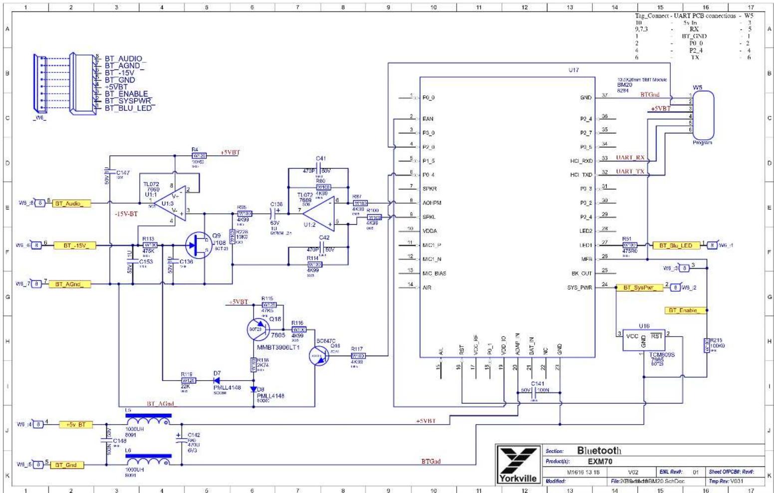


THIS SHEET CONTAINS A CHANGE HISTORY LOG, A LIST OF THE POTS & KNOBS AND A LEADS & PINS REFERENCE SECTION.


PCB ASSEMBLY DOCUMENTATION
SPECIAL PRODUCTION NOTES
Heatsin Assem y PCB Finis ing

Put RTV under the base of L1 and L2 at the edges of the silkscreen outline.


Place 4144 pad on the Neatsink.
Dip cachscreewinLbotiteC6oore2 Iteahds.

RTV

Mount 6671 using theZscrews with Nihel Holstein SeneBrace between the rows of each PEGSTET plots and 4 widths.
Do not bend the leads of S1
THIS SHEET CONTAINS SPECIAL PRODUCTION NOTES AND A LIST OF PCB HARDWARE PARTS REQUIRED FOR THE BUILD.

THIS SHEET CONTAINS A CHANGE HISTORY LOG, A LIST OF THE POTS & KNOBS AND A LEADS & PINS REFERENCE SECTION.


Pensos Insgt Staalones
2016 WIS R.H. coonson 2016


| Yorkville www.yorville.com | Product: EXM70 | |||
| Description: Battery Powered PA Speaker | ||||
| M1018-18.10 | V05 | EVL Rev: 01 | Stool OP&GE Rev: | |
| Model: 2022-04-08 | BUOchelB&ME26 EdDoc | Tnp Rer: V03 | ||
| 12 | 13 | 14 | 15 | 16 |
DESIGN HISTORY AND INFORMATION
CHANGE HISTORY POTENTIETERS AND KNOBS
| # | DATE | VER# | PC# | DESCRIPTION OF CHANGE |
| 1 | 06.AUG-2020 | V01 | RELEASED FOR PRODUCTION | |
| 2 | 18SEP-2020 | V02 | 9594 | Multiple revisions per schematics in PC9684 pcl document |
| 3 | 18NOV-2020 | V03 | 9597 | Replaced 6V regulators C18 and Q19 #7918 with #8208 |
| 4 | 19NOV-2020 | V03 | 9614 | Backed off -5V copper fill and trace from mlg screw in bluetooth section. |
| 5 | 12JAN-2021 | V04 | 9619 | Rerouted battery status and S3 connections according to PC9619. |
| 6 | 13Sept-2021 | V04 | 9689 | Updated heatsink to in-house version, updated heatsink assembly instructions. |
| 7 | 07APR-2022 | V05 | 9713 | Moved C170B away from mounting hole |
| 8 | ||||
| 9 | ||||
| 10 | ||||
| 11 | ||||
| 12 | ||||
| 13 | ||||
| # | DATE | VER# | PC# | DESCRIPTION OF CHANGE |
| 1 | ||||
| 2 | ||||
| 3 | ||||
| 4 | ||||
| 5 | ||||
| 6 | ||||
| 7 | ||||
| 8 | ||||
| 9 | ||||
| 10 | ||||
| 11 | ||||
| 12 | ||||
| 13 |
| POTENTIOMETERS/SWITCHES AND KNOBS | ||||
| REF | FUNCTION | POT/SW YS# | STYLE | KNOB# |
| P1A | LEVEL | 4486 | P32 | . |
| P1B | LEVEL | 4486 | P32 | . |
| P1C | LEVEL | 4486 | P32 | . |
| P2A | Shape | 4472 | P32 | . |
| P2B | Shape | 4472 | P32 | . |
| P2C | Shape | 4472 | P32 | . |
| P3A | FX Send | 4471 | P32 | . |
| P3B | FX Send | 4471 | P32 | . |
| P3C | FX Send | 4471 | P32 | . |
| P4 | Master | 4433 | P32 | . |
| S1 | FX Select | 4189 | . | . |
| S2 | BT Pair | 3499 | . | . |
| S3 | Power | 3522 | . | . |

"STYLE.P2"
THIS SHEET CONTAINS A CHANGE HISTORY LOG. ALIST OF THE POTS & KNOBS AND A LEADS & PINS REFERENCE SECTION.

- Channel 1 Input The combi-jack is for a mic (XLR) or a balanced line leve (1/4-inch) source. 24V phantom power is present on the XLR portion of the jack.
2. Channel 2 Input
The combi-jack is for a mic (XLR) or an instrument (1/4-inch). 24V phantom power is present on the XLR portion of the jack.
3. Channel 3 Input
The XLR jack is for a mic, the 1/8-inch phone jack for media players and the Bluetooth™ for streaming audio. 24V phantom power is present on the XLR input of the jack.
Note: When Bluetooth™ is used the volume is controlled by Channel 3's Level control.
4. BluetoothTM
Bluetooth™ operating range is rated 10 meters (33 feet). The quality of the link can be affected by an excess of traffic in the 2.4 GHz bandwidth or obstructions.
Pairing
For 'Pairing' depress the Enable Button for 4 seconds and then release.

EXM
BluetoothTM
70
8. Master Control
The Master Control is used to set the overall level of the Yorkville EXM70.
Status
Slow blinking indicates pairing mode while fast blinking indicates an available, unpaired connection. A steady (solid) blue light indicates it's paired and audio is available to Channel 3.
-
Channel Level Controls The Level controls adjust the channel gain over an 85 dB range. Use these controls to adjust each channel's volume in the overall system mix. The LED indicates clipping.
-
Channel Shape Controls Setting this control towards 'Music' shapes the response to be suited for reproducing prerecorded music while setting the control towards 'Speech' accentuates the midfrequencies which help speech and vocals. The response is flat in the center position.
7. Channel Effects Controls
This control determines how much of the selected effect is applied to the corresponding channel.
9. Effects Selector
Three effects are available with this control, as well as an off (no-effects) position. The effects are Delay, Hall Reverb and Room Reverb. The selected effect is available to all 3 input channels and the amount of effect applied is controlled by the individual channel's effects knob.
10. Link Jacks
The Link jacks are used to connect multiple EXM70 systems and/or a subwoofer. The jacks are in parallel, both a male and female XLR to help make it more convenient to 'link' enclosures together. To use the Link feature, insert a standard XLR patch cable between cabinets.
11. Pole Mount
The built in pole stand adapter and can use a standard Yorkville pole-mount speaker stand.


To get the full Owner's Manual please visit our website at
http://www.yorkville.com/manuals/ or, if you need a printed version call 905-837-8777
REAL Gear.
Canada Voice: 908-837-8481
Fax: 805-839-5776
U.S.A.Voice:716-287-2920
Fax:716-297-3688

REAL People.
www.yorkville.com
Yorkville Sound
550 Granite Court
Pickering. Ontario
L1W-3Y8 CANADA
Yorkville Sound Inc.
4625 Witmer Industrial Estate
Niagara Falls, New York
14305 USA
Printed In CANADA
QuickStart-EXM70-00-1v7·YS#QSTARTEXM70·December 15,2022
1. Entre Canal 1
Niagara Falls, New York
14305 USA


ATTENTION
ELECTROSTATIC
SENSITIVE DEVICE

PCB ASSEMBLY DOCUMENTATION
SPECIAL PRODUCTION NOTES
1) Place both YS#741 screws through the heatink and secure with two YS#8793 nuts. Tighten to 4 in. lbs.

2) Add YS#4236 gappad to U8. Handle the gappad edges only, ensure the pad is centered over U8.

Heatsin Assem y PCB Finis ing
3) Place heatsink assembly from step 1 through the PCB and on top of the gappad. Hold in place from the centre with the clip.

4) Flip over the PCB and apply Permahond MM115 Threadlocker to each screw. Secure heatsink to PCB with two YS#8701 nuts. Tighten to 4 In. lbs.

The input section needs to be air tight. All vias and part holes must be filled with solder.
Apply Permabond to the end of each screw.
PCB HARDWARE

THIS SHEET CONTAINS SPECIAL PRODUCTION NOTES AND A LIST OF PCB HARDWARE PARTS REQUIRED FOR THE BUILD.

DESIGN HISTORY AND INFORMATION
CHANGE HISTORY POTENTIETERS AND KNOBS
| # | DATE | VER# | PC# | DESCRIPTION OF CHANGE |
| 1 | 06.AUG-2020 | V01 | RELEASED FOR PRODUCTION | |
| 2 | 18SEP-2020 | V02 | 9594 | Multiple revisions per schematics in PC9684 pcl document |
| 3 | 18NOV-2020 | V03 | 9597 | Replaced 6V regulators C18 and Q19 #7918 with #8208 |
| 4 | 19NOV-2020 | V03 | 9614 | Backed off -5V copper fill and trace from mlg screw in bluetooth section. |
| 5 | 12JAN-2021 | V04 | 9619 | Rerouted battery status and S3 connections according to PC9619. |
| 6 | 13Sept-2021 | V04 | 9689 | Updated heatsink to in-house version, updated heatsink assembly instructions. |
| 7 | 07APR-2022 | V05 | 9713 | Moved C170B away from mounting hole |
| 8 | ||||
| 9 | ||||
| 10 | ||||
| 11 | ||||
| 12 | ||||
| 13 | ||||
| # | DATE | VER# | PC# | DESCRIPTION OF CHANGE |
| 1 | ||||
| 2 | ||||
| 3 | ||||
| 4 | ||||
| 5 | ||||
| 6 | ||||
| 7 | ||||
| 8 | ||||
| 9 | ||||
| 10 | ||||
| 11 | ||||
| 12 | ||||
| 13 |
| POTENTIOMETERS/SWITCHES AND KNOBS | ||||
| REF | FUNCTION | POT/SW YS# | STYLE | KNOB# |
| P1A | LEVEL | 4486 | P32 | |
| P1B | LEVEL | 4486 | P32 | |
| P1C | LEVEL | 4486 | P32 | |
| P2A | Shape | 4472 | P32 | |
| P2B | Shape | 4472 | P32 | |
| P2C | Shape | 4472 | P32 | |
| P3A | FX Send | 4471 | P32 | |
| P3B | FX Send | 4471 | P32 | |
| P3C | FX Send | 4471 | P32 | |
| P4 | Master | 4433 | P32 | |
| S1 | FX Select | 4189 | ||
| S2 | BT Pair | 3499 | ||
| S3 | Power | 3522 | ||

"STYLE.P2"
THIS SHEET CONTAINS A CHANGE HISTORY LOG. ALIST OF THE POTS & KNOBS AND A LEADS & PINS REFERENCE SECTION.


SARs:Input Standalone
PcF: ^m
14212 191 R.H. 1000000000000000000000000000000000000000000000000000

| Effects selection | |
| S1 Pos Code Effect | |
| 1 | 0010 Room3b-Reverb. Room (1.8 sec.) |
| 2 | 0110 Room2a-Reverb. Chipted (3 sec.) |
| 3 | 1010 Delay7-Echo |
| 4 | N/A Off |
| Yorkville | Section: Digital Effects | |||
| Product(s): EXM70 | ||||
| PCB#: M2212 | Rev: V01 | Eng: GA, RF, RH | Sheet 4 OF 5 | |
| Modified: File:2026-5-32@1x.c | ||||
DESIGN HISTORY AND INFORMATION
CHANGE HISTORY
| # | DATE | VER# | PC# | DESCRIPTION OF CHANGE |
| 1 | 01-DEC-2023 | V01 | Release for Production | |
| 2 | ||||
| 3 | ||||
| 4 | ||||
| 5 | ||||
| 6 | ||||
| 7 | ||||
| 8 | ||||
| 9 | ||||
| 10 | ||||
| 11 | ||||
| 12 | ||||
| 13 | ||||
| # | DATE | VER# | PC# | DESCRIPTION OF CHANGE |
| 1 | ||||
| 2 | ||||
| 3 | ||||
| 4 | ||||
| 5 | ||||
| 6 | ||||
| 7 | ||||
| 8 | ||||
| 9 | ||||
| 10 | ||||
| 11 | ||||
| 12 | ||||
| 13 |
POTENTIOMETERS AND KNOBS
| POTENTIMETERS/SWITCHES AND KNORS | |||
| REF | FUNCTION | POT/SW YS# | STYLE |
| P1A | LEVEL | 4466 | P32 |
| P1B | LEVEL | 4486 | P32 |
| P1C | LEVEL | 4486 | P32 |
| P2A | Shape | 4472 | P32 |
| P2B | Shape | 4472 | P32 |
| P2C | Shape | 4472 | P32 |
| P3A | FX Send | 4471 | P32 |
| P3B | FX Send | 4471 | P32 |
| P3C | FX Send | 4471 | P32 |
| P4 | Master | 4453 | P32 |
| S1 | FX Select | 4189 | - |
| S2 | BT_Pair | 3499 | - |
| S3 | Power | 3522 | - |

STYLE P8
THIS SHEET CONTAINS A CHANGE HISTORY LOG.A LIST OF THE POTS & KNOBS AND A LEADS & PINS REFERENCE SECTION.

Yorkville
Design Information And History
Project: EXMT05
14223 W1 84. RR, RTy, Jw#ow#e# w##

M2212-EXM70
V01
PCB ASSEMBLY DOCUMENTATION
SPECIAL PRODUCTION NOTES
- This board uses a wave soldering jig. Ensure all connectors and switches are flush to the surface of the board before placing soldering jig.
Afer Wave
- Inspect bottom of board to ensure all vias are filled with solder.
- Separate panel where applicable using pizza cutter and separation(breaking) pliers.

DESIGN HISTORY AND INFORMATION
CHANGE HISTORY
| # | DATE | VER# | PC# | DESCRIPTION OF CHANGE |
| 1 | 01-DEC-2023 | V01 | Release for Production | |
| 2 | ||||
| 3 | ||||
| 4 | ||||
| 5 | ||||
| 6 | ||||
| 7 | ||||
| 8 | ||||
| 9 | ||||
| 10 | ||||
| 11 | ||||
| 12 | ||||
| 13 | ||||
| # | DATE | VER# | PC# | DESCRIPTION OF CHANGE |
| 1 | ||||
| 2 | ||||
| 3 | ||||
| 4 | ||||
| 5 | ||||
| 6 | ||||
| 7 | ||||
| 8 | ||||
| 9 | ||||
| 10 | ||||
| 11 | ||||
| 12 | ||||
| 13 |
POTENTIOMETERS AND KNOBS
| POTENTIMETERS/SWITCHES AND KNORS | |||
| REF | FUNCTION | POT/SW YS# | STYLE |
| P1A | LEVEL | 4466 | P32 |
| P1B | LEVEL | 4486 | P32 |
| P1C | LEVEL | 4486 | P32 |
| P2A | Shape | 4472 | P32 |
| P2B | Shape | 4472 | P32 |
| P2C | Shape | 4472 | P32 |
| P3A | FX Send | 4471 | P32 |
| P3B | FX Send | 4471 | P32 |
| P3C | FX Send | 4471 | P32 |
| P4 | Master | 4453 | P32 |
| S1 | FX Select | 4189 | |
| S2 | BT_Pair | 3499 | |
| S3 | Power | 3522 | |

STYLE P8
THIS SHEET CONTAINS A CHANGE HISTORY LOG. A LIST OF THE POTS & KNOBS AND A LEADS & PINS REFERENCE SECTION.

Yorkville
Design Information And History
EXMY70
14223 W1 94. RR. Ryt. Joun oceae aee


DESIGN HISTORY AND INFORMATION
CHANGE HISTORY
| # | DATE | VER# | PC# | DESCRIPTION OF CHANGE |
| 1 | 01-DEC-2023 | V01 | Release for Production | |
| 2 | ||||
| 3 | ||||
| 4 | ||||
| 5 | ||||
| 6 | ||||
| 7 | ||||
| 8 | ||||
| 9 | ||||
| 10 | ||||
| 11 | ||||
| 12 | ||||
| 13 | ||||
| # | DATE | VER# | PC# | DESCRIPTION OF CHANGE |
| 1 | ||||
| 2 | ||||
| 3 | ||||
| 4 | ||||
| 5 | ||||
| 6 | ||||
| 7 | ||||
| 8 | ||||
| 9 | ||||
| 10 | ||||
| 11 | ||||
| 12 | ||||
| 13 | ||||
| # | DATE | VER# | PC# | DESCRIPTION OF CHANGE |
| 1 | ||||
| 2 | ||||
| 3 | ||||
| 4 | ||||
| 5 | ||||
| 6 | ||||
| 7 | ||||
| 8 | ||||
| 9 | ||||
| 10 |
THIS SHEET CONTAINS A CHANGE HISTORY LOG. A LIST OF THE POTS & KNOBS AND A LEADS & PINS REFERENCE SECTION.

M2213-EXM70
V01
SPECIAL PRODUCTION NOTES
- Follow instructions below to attach heatsink Z1891 to board.
- Add RTV to the underside of L5 where indicated.
- Inspect bottom of board to ensure vias are filled with solder.
- Separate panel with pizza cutter and/or appropriate break out tool.
IMPORTANT!
BEFORE WAVE SOLDER
- ADD Scleromask dots to the two threaded spacers to bottom side of pcb.

AFTER WAVE SOLDER
- Remove the Kapton tape both sides of the board from the spacers.

Heatsin Assem y PCB Finis ing
2 Remove YS44236 gappad from sheet and apply sticky side down to the top of U8. Handle the gappad edges only, ensure the pad is centered over U8.


3_Clape HS1 (YS# Z1891) Heatsink directly on top of U8. Use legend outline as a guide.

- Secure heatsink HS1 with two 9441 screws. Tighten to 8 Inch lbs and make sure heatsink is sitting flat to spacers.

DESIGN HISTORY AND INFORMATION
CHANGE HISTORY
| # | DATE | VER# | PC# | DESCRIPTION OF CHANGE |
| 1 | 01-DEC-2023 | V01 | Release for Production | |
| 2 | ||||
| 3 | ||||
| 4 | ||||
| 5 | ||||
| 6 | ||||
| 7 | ||||
| 8 | ||||
| 9 | ||||
| 10 | ||||
| 11 | ||||
| 12 | ||||
| 13 | ||||
| # | DATE | VER# | PC# | DESCRIPTION OF CHANGE |
| 1 | ||||
| 2 | ||||
| 3 | ||||
| 4 | ||||
| 5 | ||||
| 6 | ||||
| 7 | ||||
| 8 | ||||
| 9 | ||||
| 10 | ||||
| 11 | ||||
| 12 | ||||
| 13 | ||||
| # | DATE | VER# | PC# | DESCRIPTION OF CHANGE |
| 1 | ||||
| 2 | ||||
| 3 | ||||
| 4 | ||||
| 5 | ||||
| 6 | ||||
| 7 | ||||
| 8 | ||||
| 9 | ||||
| 10 |
THIS SHEET CONTAINS A CHANGE HISTORY LOG, A LIST OF THE POTS & KNOBS AND A LEADS & PINS REFERENCE SECTION.


- SERVICE MANUAL
- EXM70
- SMT Disclaimer
- IMPORTANT SAFETY INSTRUCTIONS
- FOLLOW ALL INSTRUCTIONS SUVEZ TOUTES LES INSTRUCTIONS
- CAUTION: TO REDUCE THE RISK OF ELECTRIC SHOCK, DO NOT REMOVE COVER (OR BACK).
- Power Sources
- Hazards
- Power Cord
- Service
- WARNING
- DESIGN HISTORY AND INFORMATION
- PCB ASSEMBLY DOCUMENTATION
- Channel 2 Input
- Channel 3 Input
- BluetoothTM
- Pairing
- EXM
- 70
- Master Control
- Status
- Channel Effects Controls
- Effects Selector
- Link Jacks
- Pole Mount
- Entre Canal 1
- ATTENTION
- SPECIAL PRODUCTION NOTES
- Heatsin Assem y PCB Finis ing
- PCB HARDWARE
- IMPORTANT!
- BEFORE WAVE SOLDER
- AFTER WAVE SOLDER
Brand : YORKVILLE
Model : Excursion Mini EXM70
Category : Loudspeaker